EP0562007B1 - Remote actuating apparatus comprising a keypad controlled transmitter and a fixed code transmitter - Google Patents
Remote actuating apparatus comprising a keypad controlled transmitter and a fixed code transmitter Download PDFInfo
- Publication number
- EP0562007B1 EP0562007B1 EP92902767A EP92902767A EP0562007B1 EP 0562007 B1 EP0562007 B1 EP 0562007B1 EP 92902767 A EP92902767 A EP 92902767A EP 92902767 A EP92902767 A EP 92902767A EP 0562007 B1 EP0562007 B1 EP 0562007B1
- Authority
- EP
- European Patent Office
- Prior art keywords
- type
- code
- door
- stored
- keypad
- Prior art date
- Legal status (The legal status is an assumption and is not a legal conclusion. Google has not performed a legal analysis and makes no representation as to the accuracy of the status listed.)
- Expired - Lifetime
Links
- 238000003860 storage Methods 0.000 claims abstract description 14
- 230000007774 longterm Effects 0.000 claims abstract description 8
- 230000004044 response Effects 0.000 claims description 17
- 230000003993 interaction Effects 0.000 claims description 4
- 230000002401 inhibitory effect Effects 0.000 claims 1
- 238000003825 pressing Methods 0.000 abstract description 6
- 238000010586 diagram Methods 0.000 description 20
- 239000004020 conductor Substances 0.000 description 14
- 230000005540 biological transmission Effects 0.000 description 13
- 230000000994 depressogenic effect Effects 0.000 description 1
- 238000001514 detection method Methods 0.000 description 1
- 238000011156 evaluation Methods 0.000 description 1
- 238000004519 manufacturing process Methods 0.000 description 1
- 238000012986 modification Methods 0.000 description 1
- 230000004048 modification Effects 0.000 description 1
- 238000002360 preparation method Methods 0.000 description 1
- 230000003252 repetitive effect Effects 0.000 description 1
- 230000004043 responsiveness Effects 0.000 description 1
Images


Classifications
-
- G—PHYSICS
- G07—CHECKING-DEVICES
- G07C—TIME OR ATTENDANCE REGISTERS; REGISTERING OR INDICATING THE WORKING OF MACHINES; GENERATING RANDOM NUMBERS; VOTING OR LOTTERY APPARATUS; ARRANGEMENTS, SYSTEMS OR APPARATUS FOR CHECKING NOT PROVIDED FOR ELSEWHERE
- G07C9/00—Individual registration on entry or exit
- G07C9/00174—Electronically operated locks; Circuits therefor; Nonmechanical keys therefor, e.g. passive or active electrical keys or other data carriers without mechanical keys
- G07C9/00182—Electronically operated locks; Circuits therefor; Nonmechanical keys therefor, e.g. passive or active electrical keys or other data carriers without mechanical keys operated with unidirectional data transmission between data carrier and locks
-
- E—FIXED CONSTRUCTIONS
- E05—LOCKS; KEYS; WINDOW OR DOOR FITTINGS; SAFES
- E05F—DEVICES FOR MOVING WINGS INTO OPEN OR CLOSED POSITION; CHECKS FOR WINGS; WING FITTINGS NOT OTHERWISE PROVIDED FOR, CONCERNED WITH THE FUNCTIONING OF THE WING
- E05F15/00—Power-operated mechanisms for wings
- E05F15/70—Power-operated mechanisms for wings with automatic actuation
- E05F15/77—Power-operated mechanisms for wings with automatic actuation using wireless control
-
- E—FIXED CONSTRUCTIONS
- E05—LOCKS; KEYS; WINDOW OR DOOR FITTINGS; SAFES
- E05Y—INDEXING SCHEME ASSOCIATED WITH SUBCLASSES E05D AND E05F, RELATING TO CONSTRUCTION ELEMENTS, ELECTRIC CONTROL, POWER SUPPLY, POWER SIGNAL OR TRANSMISSION, USER INTERFACES, MOUNTING OR COUPLING, DETAILS, ACCESSORIES, AUXILIARY OPERATIONS NOT OTHERWISE PROVIDED FOR, APPLICATION THEREOF
- E05Y2900/00—Application of doors, windows, wings or fittings thereof
- E05Y2900/10—Application of doors, windows, wings or fittings thereof for buildings or parts thereof
- E05Y2900/13—Type of wing
- E05Y2900/132—Doors
-
- G—PHYSICS
- G07—CHECKING-DEVICES
- G07C—TIME OR ATTENDANCE REGISTERS; REGISTERING OR INDICATING THE WORKING OF MACHINES; GENERATING RANDOM NUMBERS; VOTING OR LOTTERY APPARATUS; ARRANGEMENTS, SYSTEMS OR APPARATUS FOR CHECKING NOT PROVIDED FOR ELSEWHERE
- G07C9/00—Individual registration on entry or exit
- G07C9/00174—Electronically operated locks; Circuits therefor; Nonmechanical keys therefor, e.g. passive or active electrical keys or other data carriers without mechanical keys
- G07C9/00182—Electronically operated locks; Circuits therefor; Nonmechanical keys therefor, e.g. passive or active electrical keys or other data carriers without mechanical keys operated with unidirectional data transmission between data carrier and locks
- G07C2009/00206—Electronically operated locks; Circuits therefor; Nonmechanical keys therefor, e.g. passive or active electrical keys or other data carriers without mechanical keys operated with unidirectional data transmission between data carrier and locks the keyless data carrier being hand operated
- G07C2009/00214—Electronically operated locks; Circuits therefor; Nonmechanical keys therefor, e.g. passive or active electrical keys or other data carriers without mechanical keys operated with unidirectional data transmission between data carrier and locks the keyless data carrier being hand operated by one push button
-
- G—PHYSICS
- G07—CHECKING-DEVICES
- G07C—TIME OR ATTENDANCE REGISTERS; REGISTERING OR INDICATING THE WORKING OF MACHINES; GENERATING RANDOM NUMBERS; VOTING OR LOTTERY APPARATUS; ARRANGEMENTS, SYSTEMS OR APPARATUS FOR CHECKING NOT PROVIDED FOR ELSEWHERE
- G07C9/00—Individual registration on entry or exit
- G07C9/00174—Electronically operated locks; Circuits therefor; Nonmechanical keys therefor, e.g. passive or active electrical keys or other data carriers without mechanical keys
- G07C9/00182—Electronically operated locks; Circuits therefor; Nonmechanical keys therefor, e.g. passive or active electrical keys or other data carriers without mechanical keys operated with unidirectional data transmission between data carrier and locks
- G07C2009/00206—Electronically operated locks; Circuits therefor; Nonmechanical keys therefor, e.g. passive or active electrical keys or other data carriers without mechanical keys operated with unidirectional data transmission between data carrier and locks the keyless data carrier being hand operated
- G07C2009/00222—Electronically operated locks; Circuits therefor; Nonmechanical keys therefor, e.g. passive or active electrical keys or other data carriers without mechanical keys operated with unidirectional data transmission between data carrier and locks the keyless data carrier being hand operated by more than one push button
-
- G—PHYSICS
- G07—CHECKING-DEVICES
- G07C—TIME OR ATTENDANCE REGISTERS; REGISTERING OR INDICATING THE WORKING OF MACHINES; GENERATING RANDOM NUMBERS; VOTING OR LOTTERY APPARATUS; ARRANGEMENTS, SYSTEMS OR APPARATUS FOR CHECKING NOT PROVIDED FOR ELSEWHERE
- G07C9/00—Individual registration on entry or exit
- G07C9/00174—Electronically operated locks; Circuits therefor; Nonmechanical keys therefor, e.g. passive or active electrical keys or other data carriers without mechanical keys
- G07C2009/00753—Electronically operated locks; Circuits therefor; Nonmechanical keys therefor, e.g. passive or active electrical keys or other data carriers without mechanical keys operated by active electrical keys
- G07C2009/00769—Electronically operated locks; Circuits therefor; Nonmechanical keys therefor, e.g. passive or active electrical keys or other data carriers without mechanical keys operated by active electrical keys with data transmission performed by wireless means
- G07C2009/00793—Electronically operated locks; Circuits therefor; Nonmechanical keys therefor, e.g. passive or active electrical keys or other data carriers without mechanical keys operated by active electrical keys with data transmission performed by wireless means by Hertzian waves
-
- G—PHYSICS
- G07—CHECKING-DEVICES
- G07C—TIME OR ATTENDANCE REGISTERS; REGISTERING OR INDICATING THE WORKING OF MACHINES; GENERATING RANDOM NUMBERS; VOTING OR LOTTERY APPARATUS; ARRANGEMENTS, SYSTEMS OR APPARATUS FOR CHECKING NOT PROVIDED FOR ELSEWHERE
- G07C2209/00—Indexing scheme relating to groups G07C9/00 - G07C9/38
- G07C2209/04—Access control involving a hierarchy in access rights
Definitions
- the present invention relates to remote actuating apparatus capable of responding to multiple types of security codes including security codes generated from storage at a transmitter and from keypad generation at a transmitter.
- Remote actuating apparatus such as automatic garage door openers comprise remote transmitters and a receiver which responds to signals from the transmitters to generate actuating signals thereby opening a door.
- the receivers of such arrangements provide security in their operation by actuating only when a properly transmitted request is received which matches one of the small number of allowable security codes.
- the security codes are used to deny access by miscreants and to limit the possibility that someone with a similar transmitter would erroneously open garage doors other than his or her own.
- the second basic type of code transmitter does not include long term security code storage, but instead, includes a keypad which the user manipulates to define a particular security code which the user has memorized.
- the long term storage of the transmitter is replaced with human memory.
- the keypad-type transmitter can only be used to open a door by people knowing the proper code to enter. Should a keypad-type transmitter be lost or stolen, it includes no memory of the security code to be used and thus, an individual who comes into possession of the transmitter without the owner's permission cannot automatically control a receiver.
- Keypad transmitters are much less convenient to use than stored code transmitters because the code must be remembered and re-entered for each use of the keypad transmitter. Also, when a user's arms are full of packages or when the user is driving a car, keypad code entry can be physically difficult.
- EP-A-0,099,762 which describes the remote control of, for example, a garage door by means of encoded signals.
- a garage door opening system in accordance with the present invention comprises a door actuating apparatus which responds to door open request signals from remote transmitters of a keypad type and from remote transmitters of the long-term storage type by selectively opening a garage door.
- an operator controlled security switch is included at the door actuating apparatus which enables the operator to lock out the stored code type door open requests, while permitting keypad type door open requests to selectively open the door.
- the actuation apparatus opens the door and responds to both types of door open requests.
- the security switch setting can be changed to lock out the stored code type transmitter.
- the door actuation apparatus can also be controlled to inhibit all door actuation, regardless of the type of the door open request signals received.
- Each type of door open request includes a security code sequence which is distinguishable from the security code sequence of the other types of door open requests.
- the actuating apparatus includes a memory for storing permitted security code sequences of both the keypad type and the stored code type. The permitted code sequences are those which are permitted to open the door.
- the door actuating apparatus determines the type of received request and compares the security code of the received request with the same type of stored permitted code sequence. When the compared code sequences are the same, a door actuation signal is generated.
- the door actuation signal generated in response to a received stored code type door open request may be inhibited by the setting of the security switch.
- a door opening apparatus in accordance with the present invention can respond to two formats of stored code type security signals and to the keypad type security signals.
- the actuation apparatus comprises memory for storing at least one permitted stored code of all three possible types of received door open requests.
- a door open request is received, its type and format are determined and it is compared with the same type of stored permitted code sequence.
- door actuation signals are generated.
- the security switch is controlled to be in the increased security mode, door actuation signals responsive to both types of stored security code transmitters are inhibited, while those of a keypad transmitter are not.
- FIG. 1 illustrates a garage door operator 10 mounted to the ceiling of a garage and connected to operate a door 17.
- Garage door operator 10 has a head end unit 11 which is supported from the ceiling and includes a motor (not shown) which drives a suitable chain 15 to which a trolley 13 is attached so that it moves along rail 12.
- the trolley 13 has a release cord 20 and pivotally carries a lever arm 14 which is attached to a bracket 16 mounted to the door, so as to raise and open it by pulling along conventional rails 19.
- head end unit 11 lowers the door by moving trolley 13 away from the head end unit 11 until the door has achieved the closed position.
- Head end unit 11 includes an operating mechanism which energizes the motor to open and close the door.
- the operating mechanism is actuated in response to an actuation signal transmitted over a conductor 18 from a control unit 38.
- Control unit 38 generates the actuation signal on conductor 18 in response to an operate switch 39 on the control unit 38 and in response to door actuation request signals from remote transmitters 24 through 26.
- the door actuation request signals from remote transmitters 24 through 26, each comprise a sequence of code words which must match a sequence of allowable code words stored in control unit 38 before actuation signals are generated on conductor 18.
- remote transmitters 24 and 25 transmit in a 10 code word format in which each door actuation request signal includes 10 code words and remote transmitter 26 transmits in a 20 code word format in which each door actuation request signal includes 20 code words.
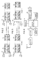
- FIG. 2 represents a door actuation request signal of the 10 code word format in which ten code words 41 make up the security code proper.
- Each of the code words 41 comprises 4-bits which are used to convey one of three code designations. The coding of these three designations, which are labelled A, B and C is shown in Table 1. Since each of the code words 41 indicates one of three states and ten such words exist in a code sequence, approximately 59,000 unique code word sequences can be created with the 10 code word coding format.
- the code words are transmitted from a transmitter to a control unit 38 using RF signals and each sequence of code words begins with a single logic one synchronization pulse 42 (FIG. 2).
- a blanking interval is produced by the transmitter of approximately 39-bit intervals, then the entire code sequence beginning with the logic one synchronization pulse 42, is repeated. Transmission in this manner results in a continuing sequence of transmitted 10 word code sequences, each separated by 39 blank bit times and each beginning with a logic one synchronization pulse 42.
- Control unit 38 recognizes the 10 code word format recognizes the format by the presence of the one bit time synchronization pulse 42 following a blanking interval and records each successive sequence of ten code words. As is well known in the art, multiple repetitions of the same code word sequence are received before the code word sequence is determined to have been received correctly.
- FIG. 3 represents a 20 code word sequence of the present embodiment.
- the 20 code word sequence of FIG. 3 comprises two frames of code words where a frame 1 consists of code words 1 through 10 and a frame 2 consists of code words 11 through 20.
- the code words of frame 1 are denoted 44 and those of frame 2 are denoted 49.
- a code sequence of 20 three state code words as shown in FIG. 3 permits in excess of three billion unique code combinations.
- Each frame 1 is transmitted using substantially the same format as each frame of the 10 code word system and begins with a logic one synchronization pulse 42 and ends with a blanking interval of approximately 39-bit times.
- Each frame 2 is transmitted at the end of the blanking interval and begins with a synchronization 2 signal 46 which comprises three consecutive logic ones.
- another blanking interval is enforced followed by repetitive transmissions of frame 1 and frame 2, each separated by a blanking interval and each frame 2 beginning with a 3-bit synchronization signal 46.
- the code word sequence to be transmitted is stored in a memory in transmitters 24 and 26, while the code word sequence transmitted by transmitter 25 is entered by user manipulation of a push button keys 27 (FIG. 1).
- FIG. 4 is a block diagram of a transmitter 24 which transmits pre-stored code words in the ten code word format.
- a transmit unit 31 operates in accordance with signals from a time generator 33 to read the ten permanently stored code words from a code word source 39 and convert them into RF signal bursts which are transmitted to the control unit 38 (FIG. 1) via an antenna 34.
- the transmitter of FIG. 4 is normally at rest.
- push button 36 When an operator wishes to transmit a code, that operator presses push button 36 to which timing generator 33 responds by generating a continuing sequence of clock pulses at the rate of approximately one pulse per millisecond.
- Code word source 39 is a memory which permanently stores the ten code words in the format shown in Table 1. In order to facilitate identification of the source of transmitted code word sequences, the tenth code word stored by code word source 39 is always a code character "A" as shown in Table 1.
- time generator 33 may include a delay device such as a monostable multi-vibrator (not shown) which keeps timing generator 33 operational for a predetermined period of time regardless of the time that the button 36 is actually held down. Such preset operation of timing generator 33 assures that a minimum number of code word sequences is transmitted for each push of button 36.
- a delay device such as a monostable multi-vibrator (not shown) which keeps timing generator 33 operational for a predetermined period of time regardless of the time that the button 36 is actually held down.
- FIG. 5 is a block diagram representation of a transmitter 26 for transmitting 20 code word sequences of the type shown in FIG. 3.
- a transmit unit 51 operates in accordance with signals from a time generator 53 to read permanently stored code words from a code word source 59 and convert them into RF signal bursts which are transmitted to the control unit 38 (FIG. 1) via an antenna 54.
- the transmitter of FIG. 5 is normally at rest.
- timing generator 53 responds by generating a continuing sequence of clock pulses at the rate of approximately one pulse per millisecond.
- These clock pulses are applied to transmit unit 51 via a conductor 57 and control the reading and transmission of code words.
- FIG. 6 is a flow diagram of the operation of the transmitter of FIG. 5 and is discussed in conjunction with the operation of the transmitter of FIG. 5.
- the sequence shown in FIG. 6 begins at block 60 with the detection of the closure of push-button 56. Pressing button 56 causes time generator 53 to generate a recurring sequence of timing pulses at the rate of one per millisecond.
- transmit unit 51 transmits via antenna 54, a logic one, synchronization 1 signal of 1-bit time duration (one millisecond).
- transmit unit 51 also begins to read code words from a code word source 59 over a communication path 58.
- the code words read from code word source 59 are transmitted in sequence at the rate of 1 code word bit per clock time until the last bit of the tenth code word has been transmitted.
- transmit unit 51 blanks all transmission for 39 bit times (block 66).
- Transmitter 51 terminates the blanking interval by transmitting a synchronization 2 signal consisting of three consecutive logic ones (block 68).
- code words 11 through 20 which are accessed from code word source 59 are transmitted in a manner substantially identical to the transmission of code words 1 through 10.
- the flow diagram proceeds to block 71 where another blank interval of 39-bit times is inserted and the flow proceeds back to block 60 where a determination is made of the state of push-button 56. If push-button 56 is still closed, the sequence 60 through 71 repeats itself.
- time generator 53 may include a delay device, such a monostable multivibrator (not shown) which keeps timing generator 53 operational for a predetermined period of time, regardless of the time the button 56 is actually held down. Such preset operation of timing generator 53 assures that a minimum number of code word sequences is transmitted for each push of button 56.
- code word source 59 comprises a memory storing the 4-bit codes of the type shown in Table 1. Since twenty 3-state code words are used in the present embodiment, in excess of three billion possible codes are represented. With such a large number of possible codes, the code word sequences of all transmitters can be virtually guaranteed to be distinct.
- Keypad transmitter 25 which is shown in block diagram form in FIG. 7 does not include long term storage of a security code, but briefly registers 10 code words derived from four number key 27 presses. The registered code words are transmitted if a transmit key 61 is pressed within a short period (10 to 20 seconds) of time after the first number key is pressed. When the four keys of the code and the transmit key are not pressed within the short period of time, the registered code words are made unavailable (erased) so that no keypad transmitter finder or thief can use transmitter stored information to gain access to a protected door.
- the time of code word registration i.e., 10-20 seconds, is kept brief to provide little more than enough time for a slow operator to enter and transmit a code sequence.
- the transmitter 25 shown in FIG. 7 is now described in conjunction with the flow diagram of FIG. 8.
- the transmitter 25 includes a keypad unit 60 having ten number keys 27 and a transmit key 61.
- the transmitter of FIG. 7 normally is awaiting the press of a number key and in this waiting mode (block 130, FIG. 8), only the keypad unit 60 is receiving power input.
- a keypad number key 27 is pressed, a signal is sent on conductor 62 to a power switch 63 which then applies power via a conductor 64 to a light 65, a controller 66 and an RF transmitter 67.
- Light 65 which may comprise a plurality of light emitting diodes, produces a light when it receives power on conductor 64 to indicate to the operator that at least a partial security code sequence is registered in the transmitter 25.
- Keypad unit 60 also responds to the press of a number key 27 by transmitting a four-digit binary code representation of the particular key pressed to control 66 via a communication path 68.
- the four-digit binary code consisting of all zeros is not used to represent any key so that all number key representations include at least a single logic 1.
- control 66 When control 66 receives a representation of a first key press from communication path 68, it proceeds to a block 131 where a ten-second timer T10 is started. Controller 66 also encodes the received key press representation into the Table 1 format in preparation for transmission to control unit 38. Each key pad entered code consists of four key presses. Each of the four key press representations of a keypad entered code is encoded by control 66 into two code words as shown in Table 2 for a total of eight code words. TABLE 2 Received Key Press Code Words Registered 1 C and C 2 A and C 3 B and C 4 C and B 5 A and B 6 B and B 7 C and A 8 A and A 9 B and A 0 B and A
- the ninth code word is then selected in accordance with Table 3. TABLE 3 9th Code Word IF A Key 0 not pressed B Key 0 pressed and key 9 not pressed C Key 0 and 9 both pressed
- the tenth code word registered for all keypad type transmitter code word sequences is selected at the time of manufacture to be one of code words "B" or "C", that is, some keypad transmitters 25 will always register a code word “B” as the tenth code word and other keypad transmitters will always register a code “C” as the tenth code word. However, no keypad transmitter 25 will register a code word "A" as the tenth code word.
- control 66 As each key press representation is received by control 66, it is encoded and registered (block 132, FIG. 8) until ten code words are registered. The operator, at the completion of pressing the four keypad keys 27 of a code, presses the transmit key 61 causing a transmit signal to be sent to controller 66 via conductor 69. The registration of code words and the receipt of a transmit signal are timed (block 133) by the previously set timer T10. If the ten code words are not registered and the transmit signal not received within approximately ten seconds of the setting of timer T10, the flow proceeds from block 133 to a block 134 where timers such as timer T10 are cleared and the registered code words are made unavailable (erased). After block 134, control 66 transmits a signal (block 140) on a conductor 70 (FIG. 7) to which power switch 63 responds by removing the power from conductor 64.
- control 66 sends (block 136) the registered code words to the RF transmitter 67 which transmits them to control unit 38 via antenna 71.
- a timer T20 is started (block 137).
- the transmit button 61 is pressed (block 138) within 20 seconds of starting timer T20, the code word sequence is again transmitted (block 136) and the timer T20 is restarted (block 137). Should more than 20 seconds pass after the starting or restarting of timer T20, the affirmative branch of a timer loop 139 is taken and the registered code words are made unavailable (block 134) and power is turned off (block 140).
- transmitters 24 each transmit a door request signal which identifies the type of transmitter sending the request.
- Transmitter 26 transmits in the 20 code word format (FIG. 3), which can be identified by the synchronization 2 signal 46.
- Transmitter 24 transmits in the 10 code word format (FIG. 2) and identifies its type by the fact that code word 10 is always a code character "A" (Table 1).
- Transmitter 25 also transmits in the 10 code word format and identifies its type by the fact that the code word 10 is always a character "B" or "C” (Table 1), never a code character "A".
- the code word sequences transmitted from the transmitters of FIGS. 4, 5 and 7 are received by an antenna 74 of the control unit 38 (FIG. 9) and conveyed to an RF receiver 73.
- Receiver 73 conveys the received signals to a decoder 76 which converts them to the binary format shown in Table 1 and applies them to a receiver controller 78.
- Controller 78 identifies the transmitter type and compares the received codes with permitted codes stored in a memory 79 for the received transmitter type. When a match is found, controller 78 enables door apparatus 11 via conductor 18.
- the permitted codes stored in memory 79 for each type of transmitter are recorded therein during a receiver programming mode which is initiated by the press of a program switch push-button 84.
- Control unit 38 also includes a security switch 83 which is connected to controller 78 and used to modify the response of controller 78 to received codes.
- security switch 83 When security switch 83 is in a first position, controller 78 responds to received codes from all types of transmitters 24, 25 and 26 and generates actuation signals on conductor 18 when matching security codes occur. However, when security switch 83 is in a second position, controller 78 responds only to received code sequences from keypad transmitters 25.
- the security switch 83 allows the system owner to control which type of transmitter can actuate the door. For example, if a transmitter (24, 26) of the stored code type is lost or stolen, the owner can place security switch 83 in the second position and thereby permit entry only to those individuals who know the proper keypad code.
- controller 78 presses controller 78 in the programming mode shown in the flow diagram of FIG. 10.
- the transmitter or transmitters to be used with the subject receiver can be individually enabled to transmit their respective security codes to the control unit 38 which receives those security codes and stores them as permitted codes in memory 79.
- controller 78 enters block 86 (FIG. 10) where it awaits the reception of a first frame 1 of code words from decoder 76.
- Controller 78 determines in block 86 that a frame 1 is received by analyzing the number of bits in the received synchronization signal. It should be mentioned that either a frame one of the 20 code word format (FIG. 3) or any frame of the 10 code word format (FIG.
- block 96 determines that code word 10 does not equal the code character "A"
- the flow proceeds to block 97 where the 10 code word sequence is stored in a location Y of memory 79 allocated to permitted 10 code word sequences from keypad type transmitters 25.
- block 96 determines that code word 10 equals the code character "A”
- the flow proceeds to block 98 where the received 10 code word sequence is stored in a location X of memory 79, allocated to permitted 10 code word sequences from stored code type transmitters 24.
- control unit 78 exits the program mode.
- a block 95 is performed to determine if the synchronization signal comprises three logic ones.
- a synchronization code of 3 logic ones indicates the reception of a frame 2 of code words 11 through 20.
- the program mode is exited.
- block 95 determines that the synchronization signal comprises three logic ones the code word sequence comprising the ten code words 1 through 10 held in block 90 and the newly received ten code words 11 through 20 are stored (block 99) in a location Z of memory 79 which is allocated to the storage of permitted twenty code word sequences. After the storage (block 99) of the two-frame code word sequence in memory 79, the program mode is again exited.
- the present embodiment allows the storage of one-ten code word sequence of stored code transmitter type, one-ten code word sequence of keypad transmitter type and four-twenty code word sequences.
- FIG. 10 shows the receipt of the code sequences only once before they are stored in memory 79. It may be desirable to require that an incoming code sequence be received multiple times before it is stored as a permitted sequence.
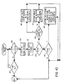
- FIG. 11 is a flow diagram of the normal operation of the controller 78 of FIG. 9 in which the controller 78 awaits an incoming code sequence for possible door actuation.
- This mode begins at block 100 where a valid frame one is awaited.
- flow proceeds to a block 102 where the 10 code words received are temporarily stored and the flow proceeds to a block 103 awaiting the next received frame.
- Block 105 is performed after a next frame is received to determine if the received frame is a frame 2 or a second occurrence of frame 1. The distinction is made by an evaluation of the length of the synchronization signal.
- the code words held in block 102 are read in block 107 and the twenty code words comprising the received frame 1 and frame 2 are compared (block 109) with the permitted twenty code word sequences stored in location Z of memory 79. Matches between received 20 code word sequences and stored permitted 20 code word sequences are identified in block 111.
- block 111 determines that the received 20 code word sequence does not match a stored permitted 20 code word sequence, control returns to block 100 to await the reception of a new frame 1.
- flow proceeds to a block 112 where the state of the security switch 83 is checked.
- security switch 83 When the security switch 83 is in its second position (called position 2), indicating that only keypad type codes are permitted to open the door, the flow proceeds from block 112 to block 100 to await the reception of a new frame 1. In normal operation, however, security switch 83 will be in its first position indicating that all types of codes are permitted to open the door.
- block 112 determines that security switch is in the first position (not in position 2), flow proceeds to a block 113 where an actuation signal is generated to open the door. After generation of the actuation signal, flow proceeds to block 100 to await the reception of a new frame 1.
- the tenth code word of the received ten code word sequence is checked in block 106 to determined whether the received code word sequence has a tenth code word equal to the character "A" (Table 1), indicating a stored code type transmitter 24, or a tenth code word equal to the characters "B" or "C” (Table 1) indicating a keypad type transmitter 25.
- the received code is compared (block 116) with the permitted keypad code stored in location Y of memory 79.
- the codes match (block 118) flow proceeds to the block 113 where an actuation signal in generated. The flow proceeds from block 118 to block 100 when no match in detected in block 118.
- block 106 determines that the received ten code word sequence is from a stored code transmitter 24
- the ten code words of the received frame 1 are compared (block 115) with the ten code word sequence stored in location X of memory 79.
- flow proceeds to block 100.
- block 117 determines that the compared code sequences match
- flow proceeds to block 119 where the position of the security switch 83 is checked.
- security switch 83 is in position 2
- flow proceeds to block 100.
- block 119 determines that the security switch is in position 1 indicating acceptance of all types of incoming codes, flow proceeds to block 113 where an actuation signal is generated.
- the state of security switch 83 is checked in blocks 112 and 119 just prior to the step of generating actuation signals.
- the placement of the comparison provided by blocks 112 and 119 can be changed to other points within the flow diagram of FIG. 11 without departing from the present invention.
- the flow diagram of FIG. 11 could be implemented as two separate flow diagrams, one operational when security switch 83 is in position 1 and the other operational when security switch 83 is in position 2.
- a two position security switch is used to indicate control unit responsiveness.
- a third position of the security switch, or an additional lock out switch can be used to disable control unit 38 response to all received door open request signals, regardless of their source.
Landscapes
- Engineering & Computer Science (AREA)
- Computer Networks & Wireless Communication (AREA)
- Physics & Mathematics (AREA)
- General Physics & Mathematics (AREA)
- Lock And Its Accessories (AREA)
- Selective Calling Equipment (AREA)
- Push-Button Switches (AREA)
Abstract
Description
- The present invention relates to remote actuating apparatus capable of responding to multiple types of security codes including security codes generated from storage at a transmitter and from keypad generation at a transmitter.
- Remote actuating apparatus such as automatic garage door openers comprise remote transmitters and a receiver which responds to signals from the transmitters to generate actuating signals thereby opening a door. The receivers of such arrangements provide security in their operation by actuating only when a properly transmitted request is received which matches one of the small number of allowable security codes. The security codes are used to deny access by miscreants and to limit the possibility that someone with a similar transmitter would erroneously open garage doors other than his or her own.
- Two basic types of security code transmitters are known in the art. One type disclosed in U.S. Patent No. 4,750,118 to C. Heitschel, et al., includes an arrangement which stores a security code on a long term or permanent basis and which transmits the stored security code in response to the pressing of a transmit push-button switch. The long term storage of the security code can be provided by a computer-type memory within the transmitter or by a set of switches within the transmitter which are only rarely changed. The stored code type of transmitter in extremely easy to use since it requires only the pressing of a transmit button. The security of such an arrangement is also good, given the large number of possible security codes that are provided for with today's remote actuation equipment. However, the code of the stored code-type transmitters remains with the transmitter and should the transmitter be lost or stolen, others can actuate the receiver with which it is paired by merely pressing a transmit button.
- The second basic type of code transmitter does not include long term security code storage, but instead, includes a keypad which the user manipulates to define a particular security code which the user has memorized. In essence, the long term storage of the transmitter is replaced with human memory. Thus, the keypad-type transmitter can only be used to open a door by people knowing the proper code to enter. Should a keypad-type transmitter be lost or stolen, it includes no memory of the security code to be used and thus, an individual who comes into possession of the transmitter without the owner's permission cannot automatically control a receiver. Keypad transmitters, however, are much less convenient to use than stored code transmitters because the code must be remembered and re-entered for each use of the keypad transmitter. Also, when a user's arms are full of packages or when the user is driving a car, keypad code entry can be physically difficult.
- Reference should also be made to EP-A-0,099,762 which describes the remote control of, for example, a garage door by means of encoded signals.
- A need exists for a door actuation arrangement which provides the security against loss or theft of a keypad transmitter while retaining the ease of use of a stored code transmitter.
- A garage door opening system in accordance with the present invention comprises a door actuating apparatus which responds to door open request signals from remote transmitters of a keypad type and from remote transmitters of the long-term storage type by selectively opening a garage door. Advantageously, an operator controlled security switch is included at the door actuating apparatus which enables the operator to lock out the stored code type door open requests, while permitting keypad type door open requests to selectively open the door.
- For normal operation, the actuation apparatus opens the door and responds to both types of door open requests. However, when greater security is desired, such as when a stored code type transmitters is lost or stolen, the security switch setting can be changed to lock out the stored code type transmitter. During the time that the stored code type transmitter is locked out, operation by the keypad type transmitter is still permitted. When greater security is no longer needed, e.g., the lost transmitter is found, controlling the security switch again permits door actuation by both types of remote transmitters. In an embodiment of the invention, the door actuation apparatus can also be controlled to inhibit all door actuation, regardless of the type of the door open request signals received.
- Each type of door open request includes a security code sequence which is distinguishable from the security code sequence of the other types of door open requests. The actuating apparatus includes a memory for storing permitted security code sequences of both the keypad type and the stored code type. The permitted code sequences are those which are permitted to open the door. In response to a received door open request, the door actuating apparatus determines the type of received request and compares the security code of the received request with the same type of stored permitted code sequence. When the compared code sequences are the same, a door actuation signal is generated. The door actuation signal generated in response to a received stored code type door open request may be inhibited by the setting of the security switch.
- For even greater utility, a door opening apparatus in accordance with the present invention can respond to two formats of stored code type security signals and to the keypad type security signals. The actuation apparatus comprises memory for storing at least one permitted stored code of all three possible types of received door open requests. When a door open request is received, its type and format are determined and it is compared with the same type of stored permitted code sequence. When the compared code sequences are the same, door actuation signals are generated. When the security switch is controlled to be in the increased security mode, door actuation signals responsive to both types of stored security code transmitters are inhibited, while those of a keypad transmitter are not.
-
- FIG. 1 is a perspective view showing a garage door operator embodying various features of the present invention;
- FIG. 2 represents a ten code word security format used with the garage door operator of FIG. 1;
- FIG. 3 represents a twenty code word security format used with the garage door operator of FIG. 1;
- FIG. 4 is a block diagram of a stored code type ten code word transmitter for use with the operator of FIG. 1;
- FIG. 5 is a block diagram of a twenty code word stored code type transmitter;
- FIG. 6 is a flow diagram of the operation of the transmitter of FIG. 5;
- FIG. 7 is a block diagram of a keypad type transmitter used with the operator of FIG. 1;
- FIG. 8 is a flow diagram of the operation of the transmitter of FIG. 7;
- FIG. 9 is a block diagram of a control unit of the operator of FIG. 1;
- FIG. 10 is a flow diagram showing a programming mode of operation for the transmitter of FIG. 9; and
- FIG. 11 is a flow diagram showing the response of the control unit to received security codes.
- FIG. 1 illustrates a
garage door operator 10 mounted to the ceiling of a garage and connected to operate adoor 17.Garage door operator 10 has a head end unit 11 which is supported from the ceiling and includes a motor (not shown) which drives a suitable chain 15 to which atrolley 13 is attached so that it moves alongrail 12. Thetrolley 13 has arelease cord 20 and pivotally carries alever arm 14 which is attached to abracket 16 mounted to the door, so as to raise and open it by pulling alongconventional rails 19. Similarly, head end unit 11 lowers the door by movingtrolley 13 away from the head end unit 11 until the door has achieved the closed position. - Head end unit 11 includes an operating mechanism which energizes the motor to open and close the door. The operating mechanism is actuated in response to an actuation signal transmitted over a
conductor 18 from acontrol unit 38.Control unit 38 generates the actuation signal onconductor 18 in response to anoperate switch 39 on thecontrol unit 38 and in response to door actuation request signals fromremote transmitters 24 through 26. The door actuation request signals fromremote transmitters 24 through 26, each comprise a sequence of code words which must match a sequence of allowable code words stored incontrol unit 38 before actuation signals are generated onconductor 18. In the present embodiment,remote transmitters remote transmitter 26 transmits in a 20 code word format in which each door actuation request signal includes 20 code words. - FIG. 2 represents a door actuation request signal of the 10 code word format in which ten
code words 41 make up the security code proper. Each of thecode words 41 comprises 4-bits which are used to convey one of three code designations. The coding of these three designations, which are labelled A, B and C is shown in Table 1. Since each of thecode words 41 indicates one of three states and ten such words exist in a code sequence, approximately 59,000 unique code word sequences can be created with the 10 code word coding format. -
TABLE 1 Code Character Transmitted Code Bit-1 Bit-2 Bit-3 Bit-4 A 0 0 0 1 B 0 0 1 1 C 0 1 1 1 - The code words are transmitted from a transmitter to a
control unit 38 using RF signals and each sequence of code words begins with a single logic one synchronization pulse 42 (FIG. 2). After the transmission of a complete ten word code sequence, a blanking interval is produced by the transmitter of approximately 39-bit intervals, then the entire code sequence beginning with the logic onesynchronization pulse 42, is repeated. Transmission in this manner results in a continuing sequence of transmitted 10 word code sequences, each separated by 39 blank bit times and each beginning with a logic onesynchronization pulse 42.Control unit 38 recognizes the 10 code word format recognizes the format by the presence of the one bittime synchronization pulse 42 following a blanking interval and records each successive sequence of ten code words. As is well known in the art, multiple repetitions of the same code word sequence are received before the code word sequence is determined to have been received correctly. - FIG. 3 represents a 20 code word sequence of the present embodiment. The 20 code word sequence of FIG. 3 comprises two frames of code words where a
frame 1 consists ofcode words 1 through 10 and aframe 2 consists of code words 11 through 20. The code words offrame 1 are denoted 44 and those offrame 2 are denoted 49. A code sequence of 20 three state code words as shown in FIG. 3 permits in excess of three billion unique code combinations. - 20 code word sequences are transmitted in a manner different from the 10 code word sequences. Each
frame 1 is transmitted using substantially the same format as each frame of the 10 code word system and begins with a logic onesynchronization pulse 42 and ends with a blanking interval of approximately 39-bit times. Eachframe 2, however, is transmitted at the end of the blanking interval and begins with asynchronization 2signal 46 which comprises three consecutive logic ones. At the conclusion of the transmission of aframe 2, another blanking interval is enforced followed by repetitive transmissions offrame 1 andframe 2, each separated by a blanking interval and eachframe 2 beginning with a 3-bit synchronization signal 46. - Regardless of whether a 10 or 20 code word format is used by a given transmitter, the code words of the format must be accurately produced by that transmitter. The code word sequence to be transmitted is stored in a memory in
transmitters transmitter 25 is entered by user manipulation of a push button keys 27 (FIG. 1). - FIG. 4 is a block diagram of a
transmitter 24 which transmits pre-stored code words in the ten code word format. In FIG. 4, a transmitunit 31 operates in accordance with signals from atime generator 33 to read the ten permanently stored code words from acode word source 39 and convert them into RF signal bursts which are transmitted to the control unit 38 (FIG. 1) via an antenna 34. The transmitter of FIG. 4 is normally at rest. When an operator wishes to transmit a code, that operator pressespush button 36 to whichtiming generator 33 responds by generating a continuing sequence of clock pulses at the rate of approximately one pulse per millisecond. These clock pulses are applied to transmitunit 31 via aconductor 37 and control the reading of the ten code words fromcode word source 39 and their transmission in the ten code word format from antenna 34.Code word source 39 is a memory which permanently stores the ten code words in the format shown in Table 1. In order to facilitate identification of the source of transmitted code word sequences, the tenth code word stored bycode word source 39 is always a code character "A" as shown in Table 1. - In order to control the minimum number of times that the code sequence is transmitted,
time generator 33 may include a delay device such as a monostable multi-vibrator (not shown) which keepstiming generator 33 operational for a predetermined period of time regardless of the time that thebutton 36 is actually held down. Such preset operation oftiming generator 33 assures that a minimum number of code word sequences is transmitted for each push ofbutton 36. - FIG. 5 is a block diagram representation of a
transmitter 26 for transmitting 20 code word sequences of the type shown in FIG. 3. A transmitunit 51 operates in accordance with signals from atime generator 53 to read permanently stored code words from acode word source 59 and convert them into RF signal bursts which are transmitted to the control unit 38 (FIG. 1) via an antenna 54. The transmitter of FIG. 5 is normally at rest. When an operator wishes to transmit a code, that operator presses a push-button 56 to whichtiming generator 53 responds by generating a continuing sequence of clock pulses at the rate of approximately one pulse per millisecond. These clock pulses are applied to transmitunit 51 via a conductor 57 and control the reading and transmission of code words. FIG. 6 is a flow diagram of the operation of the transmitter of FIG. 5 and is discussed in conjunction with the operation of the transmitter of FIG. 5. - The sequence shown in FIG. 6 begins at
block 60 with the detection of the closure of push-button 56. Pressingbutton 56 causestime generator 53 to generate a recurring sequence of timing pulses at the rate of one per millisecond. In response to a first timing pulse, transmitunit 51 transmits via antenna 54, a logic one,synchronization 1 signal of 1-bit time duration (one millisecond). At this time, transmitunit 51 also begins to read code words from acode word source 59 over acommunication path 58. Inblock 64, the code words read fromcode word source 59 are transmitted in sequence at the rate of 1 code word bit per clock time until the last bit of the tenth code word has been transmitted. At the end of transmission of the tenth code word, transmitunit 51 blanks all transmission for 39 bit times (block 66). -
Transmitter 51 terminates the blanking interval by transmitting asynchronization 2 signal consisting of three consecutive logic ones (block 68). At the conclusion of the transmission of thesynchronization 2 signal, code words 11 through 20 which are accessed fromcode word source 59 are transmitted in a manner substantially identical to the transmission ofcode words 1 through 10. At the conclusion of the transmission of code words 11 through 20, the flow diagram proceeds to block 71 where another blank interval of 39-bit times is inserted and the flow proceeds back to block 60 where a determination is made of the state of push-button 56. If push-button 56 is still closed, thesequence 60 through 71 repeats itself. Since the time required to transmit both code word frames 1 and 2, and both blanking intervals is only 182-bit times (182 milliseconds), normal human interaction with push-button 56 results in multiple transmissions of the entire 20 code word code sequence. In order to control the minimum number of times that the code sequence is transmitted,time generator 53 may include a delay device, such a monostable multivibrator (not shown) which keepstiming generator 53 operational for a predetermined period of time, regardless of the time thebutton 56 is actually held down. Such preset operation oftiming generator 53 assures that a minimum number of code word sequences is transmitted for each push ofbutton 56. - In the present embodiment,
code word source 59 comprises a memory storing the 4-bit codes of the type shown in Table 1. Since twenty 3-state code words are used in the present embodiment, in excess of three billion possible codes are represented. With such a large number of possible codes, the code word sequences of all transmitters can be virtually guaranteed to be distinct. -
Keypad transmitter 25 which is shown in block diagram form in FIG. 7 does not include long term storage of a security code, but briefly registers 10 code words derived from fournumber key 27 presses. The registered code words are transmitted if a transmit key 61 is pressed within a short period (10 to 20 seconds) of time after the first number key is pressed. When the four keys of the code and the transmit key are not pressed within the short period of time, the registered code words are made unavailable (erased) so that no keypad transmitter finder or thief can use transmitter stored information to gain access to a protected door. The time of code word registration, i.e., 10-20 seconds, is kept brief to provide little more than enough time for a slow operator to enter and transmit a code sequence. - The
transmitter 25 shown in FIG. 7 is now described in conjunction with the flow diagram of FIG. 8. Thetransmitter 25 includes akeypad unit 60 having tennumber keys 27 and a transmit key 61. The transmitter of FIG. 7 normally is awaiting the press of a number key and in this waiting mode (block 130, FIG. 8), only thekeypad unit 60 is receiving power input. When akeypad number key 27 is pressed, a signal is sent onconductor 62 to apower switch 63 which then applies power via aconductor 64 to a light 65, acontroller 66 and anRF transmitter 67.Light 65, which may comprise a plurality of light emitting diodes, produces a light when it receives power onconductor 64 to indicate to the operator that at least a partial security code sequence is registered in thetransmitter 25.Keypad unit 60 also responds to the press of anumber key 27 by transmitting a four-digit binary code representation of the particular key pressed to control 66 via acommunication path 68. The four-digit binary code consisting of all zeros is not used to represent any key so that all number key representations include at least asingle logic 1. - When
control 66 receives a representation of a first key press fromcommunication path 68, it proceeds to ablock 131 where a ten-second timer T₁₀ is started.Controller 66 also encodes the received key press representation into the Table 1 format in preparation for transmission to controlunit 38. Each key pad entered code consists of four key presses. Each of the four key press representations of a keypad entered code is encoded bycontrol 66 into two code words as shown in Table 2 for a total of eight code words.TABLE 2 Received Key Press Code Words Registered 1 C and C 2 A and C 3 B and C 4 C and B 5 A and B 6 B and B 7 C and A 8 A and A 9 B and A 0 B and A - The ninth code word is then selected in accordance with Table 3.
TABLE 3 9th Code Word IF A Key 0 not pressed B Key 0 pressed and key 9 not pressed C Key 0 and 9 both pressed - The tenth code word registered for all keypad type transmitter code word sequences is selected at the time of manufacture to be one of code words "B" or "C", that is, some
keypad transmitters 25 will always register a code word "B" as the tenth code word and other keypad transmitters will always register a code "C" as the tenth code word. However, nokeypad transmitter 25 will register a code word "A" as the tenth code word. - As each key press representation is received by
control 66, it is encoded and registered (block 132, FIG. 8) until ten code words are registered. The operator, at the completion of pressing the fourkeypad keys 27 of a code, presses the transmit key 61 causing a transmit signal to be sent tocontroller 66 viaconductor 69. The registration of code words and the receipt of a transmit signal are timed (block 133) by the previously set timer T₁₀. If the ten code words are not registered and the transmit signal not received within approximately ten seconds of the setting of timer T₁₀, the flow proceeds fromblock 133 to ablock 134 where timers such as timer T₁₀ are cleared and the registered code words are made unavailable (erased). Afterblock 134,control 66 transmits a signal (block 140) on a conductor 70 (FIG. 7) to whichpower switch 63 responds by removing the power fromconductor 64. - When the transmit signal on
conductors 69 is received (block 135) within ten seconds of the start of timer T₁₀ and all ten code words are registered,control 66 sends (block 136) the registered code words to theRF transmitter 67 which transmits them to controlunit 38 viaantenna 71. At this time, a timer T₂₀ is started (block 137). Whenever the transmitbutton 61 is pressed (block 138) within 20 seconds of starting timer T₂₀, the code word sequence is again transmitted (block 136) and the timer T₂₀ is restarted (block 137). Should more than 20 seconds pass after the starting or restarting of timer T₂₀, the affirmative branch of atimer loop 139 is taken and the registered code words are made unavailable (block 134) and power is turned off (block 140). - The three types of transmitters 24 (FIG. 4), 25 (FIG. 7) and 26 (FIG. 5), each transmit a door request signal which identifies the type of transmitter sending the request.
Transmitter 26 transmits in the 20 code word format (FIG. 3), which can be identified by thesynchronization 2signal 46.Transmitter 24 transmits in the 10 code word format (FIG. 2) and identifies its type by the fact thatcode word 10 is always a code character "A" (Table 1).Transmitter 25 also transmits in the 10 code word format and identifies its type by the fact that thecode word 10 is always a character "B" or "C" (Table 1), never a code character "A". - The code word sequences transmitted from the transmitters of FIGS. 4, 5 and 7 are received by an
antenna 74 of the control unit 38 (FIG. 9) and conveyed to anRF receiver 73.Receiver 73 conveys the received signals to adecoder 76 which converts them to the binary format shown in Table 1 and applies them to areceiver controller 78.Controller 78 identifies the transmitter type and compares the received codes with permitted codes stored in amemory 79 for the received transmitter type. When a match is found,controller 78 enables door apparatus 11 viaconductor 18. The permitted codes stored inmemory 79 for each type of transmitter are recorded therein during a receiver programming mode which is initiated by the press of a program switch push-button 84. -
Control unit 38 also includes asecurity switch 83 which is connected tocontroller 78 and used to modify the response ofcontroller 78 to received codes. Whensecurity switch 83 is in a first position,controller 78 responds to received codes from all types oftransmitters conductor 18 when matching security codes occur. However, whensecurity switch 83 is in a second position,controller 78 responds only to received code sequences fromkeypad transmitters 25. Thus, thesecurity switch 83 allows the system owner to control which type of transmitter can actuate the door. For example, if a transmitter (24, 26) of the stored code type is lost or stolen, the owner can placesecurity switch 83 in the second position and thereby permit entry only to those individuals who know the proper keypad code. - Pressing
program switch 84puts controller 78 in the programming mode shown in the flow diagram of FIG. 10. In the programming mode, the transmitter or transmitters to be used with the subject receiver can be individually enabled to transmit their respective security codes to thecontrol unit 38 which receives those security codes and stores them as permitted codes inmemory 79. When program switch 84 is initially depressed,controller 78 enters block 86 (FIG. 10) where it awaits the reception of afirst frame 1 of code words fromdecoder 76.Controller 78 determines inblock 86 that aframe 1 is received by analyzing the number of bits in the received synchronization signal. It should be mentioned that either a frame one of the 20 code word format (FIG. 3) or any frame of the 10 code word format (FIG. 2) is determined inblock 86 to be aframe 1. When noframe 1 is received within a period of time determined inblock 88, the controller exits the program mode and returns to a mode of awaiting an incoming code for door actuation purposes. If 3-bits are received inblock 86 as the synchronization signal, aframe 2 was actually received and the flow returns to the beginning to await aframe 1. - When a
frame 1 is received inblock 86, the ten code words of that frame are held in storage inblock 90 and the immediately subsequent frame is received inblock 92. After a next frame is received inblock 92, the flow proceeds to block 94 to determine if the synchronization signal received inblock 92 comprises a single logic one. When the received synchronization signal comprises a single logic one, then a 10 code word sequence is being received and the flow proceeds to block 96. Inblock 96,code word 10 is checked to identify whether the incoming code sequence is of the storedcode transmitter 24 type (FIG. 4) in whichcode word 10 equals the code character "A" (Table 1) or of thekeypad transmitter 25 type (FIG. 7) in whichcode word 10 does not equal the code character "A". Whenblock 96 determines thatcode word 10 does not equal the code character "A", the flow proceeds to block 97 where the 10 code word sequence is stored in a location Y ofmemory 79 allocated to permitted 10 code word sequences fromkeypad type transmitters 25. Alternatively, whenblock 96 determines thatcode word 10 equals the code character "A" the flow proceeds to block 98 where the received 10 code word sequence is stored in a location X ofmemory 79, allocated to permitted 10 code word sequences from storedcode type transmitters 24. After the storage of the received 10 code word sequence in either step 97 or 98,control unit 78 exits the program mode. - When the performance of
block 94 indicates that the received synchronization signal does not contain a single logic one, ablock 95 is performed to determine if the synchronization signal comprises three logic ones. A synchronization code of 3 logic ones indicates the reception of aframe 2 of code words 11 through 20. When the received synchronization signal does not comprise three logic ones, the program mode is exited. However, whenblock 95 determines that the synchronization signal comprises three logic ones the code word sequence comprising the tencode words 1 through 10 held inblock 90 and the newly received ten code words 11 through 20 are stored (block 99) in a location Z ofmemory 79 which is allocated to the storage of permitted twenty code word sequences. After the storage (block 99) of the two-frame code word sequence inmemory 79, the program mode is again exited. - Entering the program mode a number of times with different transmitters permits the storage of a number of possible permitted code words in
memory 79. The present embodiment allows the storage of one-ten code word sequence of stored code transmitter type, one-ten code word sequence of keypad transmitter type and four-twenty code word sequences. - It should be mentioned that FIG. 10 shows the receipt of the code sequences only once before they are stored in
memory 79. It may be desirable to require that an incoming code sequence be received multiple times before it is stored as a permitted sequence. An arrangement for requiring multiple valid code sequences in a substantially similar environment as described in detail in the aforementioned C. Heitschel, et al., patent. - FIG. 11 is a flow diagram of the normal operation of the
controller 78 of FIG. 9 in which thecontroller 78 awaits an incoming code sequence for possible door actuation. This mode begins atblock 100 where a valid frame one is awaited. When avalid frame 1 is received inblock 100, flow proceeds to ablock 102 where the 10 code words received are temporarily stored and the flow proceeds to ablock 103 awaiting the next received frame.Block 105 is performed after a next frame is received to determine if the received frame is aframe 2 or a second occurrence offrame 1. The distinction is made by an evaluation of the length of the synchronization signal. When the synchronization signal indicates inblock 105 that aframe 2 has been received the code words held inblock 102 are read inblock 107 and the twenty code words comprising the receivedframe 1 andframe 2 are compared (block 109) with the permitted twenty code word sequences stored in location Z ofmemory 79. Matches between received 20 code word sequences and stored permitted 20 code word sequences are identified in block 111. When block 111 determines that the received 20 code word sequence does not match a stored permitted 20 code word sequence, control returns to block 100 to await the reception of anew frame 1. Alternatively, when a match is determined in block 111 between the received 20 code word sequence and a stored permitted 20 code word sequence, flow proceeds to ablock 112 where the state of thesecurity switch 83 is checked. When thesecurity switch 83 is in its second position (called position 2), indicating that only keypad type codes are permitted to open the door, the flow proceeds fromblock 112 to block 100 to await the reception of anew frame 1. In normal operation, however,security switch 83 will be in its first position indicating that all types of codes are permitted to open the door. When block 112 determines that security switch is in the first position (not in position 2), flow proceeds to a block 113 where an actuation signal is generated to open the door. After generation of the actuation signal, flow proceeds to block 100 to await the reception of anew frame 1. - When block 105 determines that a
second frame 1 has been received after afirst frame 1, the tenth code word of the received ten code word sequence is checked inblock 106 to determined whether the received code word sequence has a tenth code word equal to the character "A" (Table 1), indicating a storedcode type transmitter 24, or a tenth code word equal to the characters "B" or "C" (Table 1) indicating akeypad type transmitter 25. When a keypad type code is identified inblock 106, the received code is compared (block 116) with the permitted keypad code stored in location Y ofmemory 79. When the codes match (block 118), flow proceeds to the block 113 where an actuation signal in generated. The flow proceeds fromblock 118 to block 100 when no match in detected inblock 118. - When block 106 determines that the received ten code word sequence is from a stored
code transmitter 24, the ten code words of the receivedframe 1 are compared (block 115) with the ten code word sequence stored in location X ofmemory 79. When the compared code sequences do not match (block 117), flow proceeds to block 100. Alternatively, when block 117 determines that the compared code sequences match, flow proceeds to block 119 where the position of thesecurity switch 83 is checked. Whensecurity switch 83 is inposition 2, flow proceeds to block 100. Alternatively, when block 119 determines that the security switch is inposition 1 indicating acceptance of all types of incoming codes, flow proceeds to block 113 where an actuation signal is generated. - In the flow diagram of FIG. 11, the state of
security switch 83 is checked inblocks blocks security switch 83 is inposition 1 and the other operational whensecurity switch 83 is inposition 2. In the preceding embodiment, a two position security switch is used to indicate control unit responsiveness. A third position of the security switch, or an additional lock out switch (not shown), can be used to disablecontrol unit 38 response to all received door open request signals, regardless of their source. - While preferred embodiments of the invention have been illustrated, it will be obvious to those skilled in the art that various modifications and changes may be made thereto without departing from the scope of the invention set forth in the attached claims.
Claims (7)
- A remote garage door opening system (10) for selectively opening a door (17), comprising:
at least one keypad transmitter (25) comprising a plurality of keys (27,61) for transmitting keypad type door opening request signals including a keypad type security code word sequence;
at least one stored code transmitter (24,26), comprising a code word sequence stored in long-term storage (39), for transmitting stored code type door open request signals, including said stored code word sequence (41), said stored code type door open request signals being distinguishable from said keypad type door open request signals;
means (73,74) for receiving door open request signals of said keypad type and for receiving door open request signals of said stored code type;
security control means (83) responsive to operator interaction for selectively generating one of a first signal indicative of door opening in response to both said keypad type door open request signals and said stored code type door open request signals, and a second signal indicative of door opening in response to only said keypad type door open request signals; and
door actuation signal generating means (78) responsive to a received door open request signal for determining the type of door open request signal received and for selectively generating door open control signals responsive to received door open request signals of both said keypad type and said stored code type when said security control means (83) is generating said first signal. - The system of Claim 1, wherein said door actuation signal generating means comprises:
means (79) for storing at least one permitted keypad type security code sequence and at least one permitted stored code type security code sequence;
means (78) for comparing a received keypad type security code sequence only with said at least one stored permitted keypad type security code sequence; and
means (78) for comparing a received stored code type security code sequence only with said at least one stored permitted stored code type security code sequence. - The system of Claim 2, wherein said door actuation signal generating means (78), while in a learning mode thereof, comprises means (78) for writing into said storing means (79) at least one permitted keypad type security code sequence and at least one permitted stored code type security code sequence.
- The system of Claim 1, wherein both said keypad type security code sequence (41) and said stored code type security code sequence comprise the same predetermined number of code words; and
said means for determining the type of door open request received comprises means for analyzing a predetermined code word of each received door open request. - The system of Claim 1, wherein said security control means (83) is responsive to operator interaction for generating a third signal and said door actuation signal generating means (78) responds to said third signal by inhibiting the opening of said door in response to all types of received door open request signals.
- A method of operating a garage door opening apparatus (11) to selectively generate actuation signals responsive to keypad type security code sequences and stored code type security code sequences, said method comprising:
storing in said apparatus (11) at least one keypad type security code sequence;
storing in said apparatus at least one stored code type security code sequence;
receiving a transmitted security code sequence including indicia of its type;
identifying the type of said received security code sequence:
comparing, responsive to said indentifying step, said received security code sequence only with the at least one of said stored permitted security code sequences of the same type; and
providing security control means (83) responsive to operator interaction for selectively generating one of a first signal indicative of door opening in response to both said keypad type door open request signals and said stored code type door open request signals, and a second signal indicative of door opening in response to only said keypad type door open request signals; and
generating actuation signals when said received security code sequence matches a permitted stored security code sequence compared thereto in said comparing step. - A method in accordance with Claim 6, comprising:
generating a security control signal indicative of door actuation only in response to received security code sequences of said keypad type; and said step of generating actuation signals comprises
generating actuation signals only in response to received security code sequences of said keypad type when said security control signals are being generated.
Applications Claiming Priority (3)
| Application Number | Priority Date | Filing Date | Title |
|---|---|---|---|
| US62690990A | 1990-12-13 | 1990-12-13 | |
| US626909 | 1990-12-13 | ||
| PCT/US1991/009266 WO1992010630A1 (en) | 1990-12-13 | 1991-12-10 | Remote actuating apparatus comprising keypad controlled transmitter |
Publications (2)
| Publication Number | Publication Date |
|---|---|
| EP0562007A1 EP0562007A1 (en) | 1993-09-29 |
| EP0562007B1 true EP0562007B1 (en) | 1995-03-15 |
Family
ID=24512383
Family Applications (1)
| Application Number | Title | Priority Date | Filing Date |
|---|---|---|---|
| EP92902767A Expired - Lifetime EP0562007B1 (en) | 1990-12-13 | 1991-12-10 | Remote actuating apparatus comprising a keypad controlled transmitter and a fixed code transmitter |
Country Status (6)
| Country | Link |
|---|---|
| EP (1) | EP0562007B1 (en) |
| JP (1) | JPH06503866A (en) |
| AU (1) | AU651651B2 (en) |
| CA (1) | CA2097425C (en) |
| DE (1) | DE69108261T2 (en) |
| WO (1) | WO1992010630A1 (en) |
Families Citing this family (6)
| Publication number | Priority date | Publication date | Assignee | Title |
|---|---|---|---|---|
| WO1992001979A1 (en) * | 1990-07-16 | 1992-02-06 | The Chamberlain Group, Inc. | Remote actuating apparatus |
| DE4233130A1 (en) * | 1992-10-02 | 1994-04-07 | Bosch Gmbh Robert | remote control |
| ES2070751B1 (en) * | 1993-05-19 | 1997-10-16 | Matos Teodosio Jose De | PERFECTED SYSTEM FOR THE OPENING OF GARAGE DOORS. |
| US5731756A (en) * | 1996-10-10 | 1998-03-24 | United Technologies Automotive, Inc. | Universal encrypted radio transmitter for multiple functions |
| US7248144B2 (en) | 2004-09-10 | 2007-07-24 | Wayne-Dalton Corp. | Barrier operator with secure/unsecure transmitter and method of use |
| DE102012107716B3 (en) * | 2012-08-22 | 2013-09-26 | Bernstein Ag | Magnetic safety switch for non-contact cooperation with actuator, transmits security code in code portions that are smaller than full data block length of security code in sections between actuator and switch |
Family Cites Families (4)
| Publication number | Priority date | Publication date | Assignee | Title |
|---|---|---|---|---|
| FR2528201B1 (en) * | 1982-06-04 | 1985-12-27 | Jacques Lewiner | IMPROVEMENTS ON CODE REMOTE DEVICES |
| DE3342557C1 (en) * | 1983-11-25 | 1985-07-25 | Audi AG, 8070 Ingolstadt | Locking system for the doors and a trunk lid of a motor vehicle |
| US4750118A (en) * | 1985-10-29 | 1988-06-07 | Chamberlain Manufacturing Corporation | Coding system for multiple transmitters and a single receiver for a garage door opener |
| DE3520397A1 (en) * | 1985-06-07 | 1986-12-11 | Audi AG, 8070 Ingolstadt | CODING METHOD |
-
1991
- 1991-12-10 EP EP92902767A patent/EP0562007B1/en not_active Expired - Lifetime
- 1991-12-10 CA CA002097425A patent/CA2097425C/en not_active Expired - Lifetime
- 1991-12-10 DE DE69108261T patent/DE69108261T2/en not_active Expired - Fee Related
- 1991-12-10 JP JP4502967A patent/JPH06503866A/en active Pending
- 1991-12-10 WO PCT/US1991/009266 patent/WO1992010630A1/en active IP Right Grant
- 1991-12-10 AU AU91480/91A patent/AU651651B2/en not_active Ceased
Also Published As
| Publication number | Publication date |
|---|---|
| EP0562007A1 (en) | 1993-09-29 |
| DE69108261T2 (en) | 1995-07-06 |
| CA2097425A1 (en) | 1992-06-14 |
| JPH06503866A (en) | 1994-04-28 |
| AU651651B2 (en) | 1994-07-28 |
| CA2097425C (en) | 2002-07-23 |
| DE69108261D1 (en) | 1995-04-20 |
| WO1992010630A1 (en) | 1992-06-25 |
| AU9148091A (en) | 1992-07-08 |
Similar Documents
| Publication | Publication Date | Title |
|---|---|---|
| US5576701A (en) | Remote actuating apparatus comprising keypad controlled transmitter | |
| EP0540621B1 (en) | Remote actuating apparatus | |
| US4988992A (en) | System for establishing a code and controlling operation of equipment | |
| US5252960A (en) | Secure keyless entry system for automatic garage door operator | |
| US8233625B2 (en) | Rolling code security system | |
| US7492898B2 (en) | Rolling code security system | |
| US7412056B2 (en) | Rolling code security system | |
| US6667684B1 (en) | Remote controlled garage door opening system | |
| EP0306598A2 (en) | Electronically programmable remote control access systems | |
| US7492905B2 (en) | Rolling code security system | |
| US4750118A (en) | Coding system for multiple transmitters and a single receiver for a garage door opener | |
| US4686529A (en) | Remote-control lock system | |
| JP2832828B2 (en) | Remote control device | |
| US20050024228A1 (en) | Method for matching transmitters and receiver | |
| EP0562007B1 (en) | Remote actuating apparatus comprising a keypad controlled transmitter and a fixed code transmitter | |
| US4633514A (en) | Keyboard controlled television receiver | |
| GB2100897A (en) | Personnel identification device | |
| JPH02296495A (en) | Keyless entry system |
Legal Events
| Date | Code | Title | Description |
|---|---|---|---|
| PUAI | Public reference made under article 153(3) epc to a published international application that has entered the european phase |
Free format text: ORIGINAL CODE: 0009012 |
|
| 17P | Request for examination filed |
Effective date: 19930607 |
|
| AK | Designated contracting states |
Kind code of ref document: A1 Designated state(s): CH DE FR GB LI |
|
| 17Q | First examination report despatched |
Effective date: 19931217 |
|
| GRAA | (expected) grant |
Free format text: ORIGINAL CODE: 0009210 |
|
| AK | Designated contracting states |
Kind code of ref document: B1 Designated state(s): CH DE FR GB LI |
|
| REF | Corresponds to: |
Ref document number: 69108261 Country of ref document: DE Date of ref document: 19950420 |
|
| ET | Fr: translation filed | ||
| PGFP | Annual fee paid to national office [announced via postgrant information from national office to epo] |
Ref country code: CH Payment date: 19951219 Year of fee payment: 5 |
|
| PLBE | No opposition filed within time limit |
Free format text: ORIGINAL CODE: 0009261 |
|
| STAA | Information on the status of an ep patent application or granted ep patent |
Free format text: STATUS: NO OPPOSITION FILED WITHIN TIME LIMIT |
|
| 26N | No opposition filed | ||
| PG25 | Lapsed in a contracting state [announced via postgrant information from national office to epo] |
Ref country code: LI Effective date: 19961231 Ref country code: CH Effective date: 19961231 |
|
| REG | Reference to a national code |
Ref country code: CH Ref legal event code: PL |
|
| REG | Reference to a national code |
Ref country code: GB Ref legal event code: IF02 |
|
| PGFP | Annual fee paid to national office [announced via postgrant information from national office to epo] |
Ref country code: FR Payment date: 20031222 Year of fee payment: 13 |
|
| PG25 | Lapsed in a contracting state [announced via postgrant information from national office to epo] |
Ref country code: FR Free format text: LAPSE BECAUSE OF NON-PAYMENT OF DUE FEES Effective date: 20050831 |
|
| REG | Reference to a national code |
Ref country code: FR Ref legal event code: ST |
|
| PGFP | Annual fee paid to national office [announced via postgrant information from national office to epo] |
Ref country code: GB Payment date: 20051212 Year of fee payment: 15 |
|
| PGFP | Annual fee paid to national office [announced via postgrant information from national office to epo] |
Ref country code: DE Payment date: 20051215 Year of fee payment: 15 |
|
| PG25 | Lapsed in a contracting state [announced via postgrant information from national office to epo] |
Ref country code: DE Free format text: LAPSE BECAUSE OF NON-PAYMENT OF DUE FEES Effective date: 20070703 |
|
| GBPC | Gb: european patent ceased through non-payment of renewal fee |
Effective date: 20061210 |
|
| PG25 | Lapsed in a contracting state [announced via postgrant information from national office to epo] |
Ref country code: GB Free format text: LAPSE BECAUSE OF NON-PAYMENT OF DUE FEES Effective date: 20061210 |