EP0561533B1 - Apparatus for radiation therapy - Google Patents
Apparatus for radiation therapy Download PDFInfo
- Publication number
- EP0561533B1 EP0561533B1 EP93301672A EP93301672A EP0561533B1 EP 0561533 B1 EP0561533 B1 EP 0561533B1 EP 93301672 A EP93301672 A EP 93301672A EP 93301672 A EP93301672 A EP 93301672A EP 0561533 B1 EP0561533 B1 EP 0561533B1
- Authority
- EP
- European Patent Office
- Prior art keywords
- fluence
- radiation
- map
- leaves
- compensator
- Prior art date
- Legal status (The legal status is an assumption and is not a legal conclusion. Google has not performed a legal analysis and makes no representation as to the accuracy of the status listed.)
- Expired - Lifetime
Links
Images



Classifications
-
- A—HUMAN NECESSITIES
- A61—MEDICAL OR VETERINARY SCIENCE; HYGIENE
- A61N—ELECTROTHERAPY; MAGNETOTHERAPY; RADIATION THERAPY; ULTRASOUND THERAPY
- A61N5/00—Radiation therapy
-
- A—HUMAN NECESSITIES
- A61—MEDICAL OR VETERINARY SCIENCE; HYGIENE
- A61B—DIAGNOSIS; SURGERY; IDENTIFICATION
- A61B6/00—Apparatus or devices for radiation diagnosis; Apparatus or devices for radiation diagnosis combined with radiation therapy equipment
- A61B6/02—Arrangements for diagnosis sequentially in different planes; Stereoscopic radiation diagnosis
- A61B6/03—Computed tomography [CT]
- A61B6/032—Transmission computed tomography [CT]
-
- A—HUMAN NECESSITIES
- A61—MEDICAL OR VETERINARY SCIENCE; HYGIENE
- A61B—DIAGNOSIS; SURGERY; IDENTIFICATION
- A61B6/00—Apparatus or devices for radiation diagnosis; Apparatus or devices for radiation diagnosis combined with radiation therapy equipment
-
- A—HUMAN NECESSITIES
- A61—MEDICAL OR VETERINARY SCIENCE; HYGIENE
- A61N—ELECTROTHERAPY; MAGNETOTHERAPY; RADIATION THERAPY; ULTRASOUND THERAPY
- A61N5/00—Radiation therapy
- A61N5/01—Devices for producing movement of radiation source during therapy
-
- A—HUMAN NECESSITIES
- A61—MEDICAL OR VETERINARY SCIENCE; HYGIENE
- A61N—ELECTROTHERAPY; MAGNETOTHERAPY; RADIATION THERAPY; ULTRASOUND THERAPY
- A61N5/00—Radiation therapy
- A61N5/10—X-ray therapy; Gamma-ray therapy; Particle-irradiation therapy
- A61N5/1042—X-ray therapy; Gamma-ray therapy; Particle-irradiation therapy with spatial modulation of the radiation beam within the treatment head
-
- G—PHYSICS
- G21—NUCLEAR PHYSICS; NUCLEAR ENGINEERING
- G21K—HANDLING OF PARTICLES OR IONISING RADIATION NOT OTHERWISE PROVIDED FOR; IRRADIATION DEVICES; GAMMA RAY OR X-RAY MICROSCOPES
- G21K1/00—Arrangements for handling particles or ionising radiation, e.g. focusing or moderating
- G21K1/02—Arrangements for handling particles or ionising radiation, e.g. focusing or moderating using diaphragms, collimators
- G21K1/04—Arrangements for handling particles or ionising radiation, e.g. focusing or moderating using diaphragms, collimators using variable diaphragms, shutters, choppers
-
- G—PHYSICS
- G21—NUCLEAR PHYSICS; NUCLEAR ENGINEERING
- G21K—HANDLING OF PARTICLES OR IONISING RADIATION NOT OTHERWISE PROVIDED FOR; IRRADIATION DEVICES; GAMMA RAY OR X-RAY MICROSCOPES
- G21K1/00—Arrangements for handling particles or ionising radiation, e.g. focusing or moderating
- G21K1/02—Arrangements for handling particles or ionising radiation, e.g. focusing or moderating using diaphragms, collimators
- G21K1/04—Arrangements for handling particles or ionising radiation, e.g. focusing or moderating using diaphragms, collimators using variable diaphragms, shutters, choppers
- G21K1/046—Arrangements for handling particles or ionising radiation, e.g. focusing or moderating using diaphragms, collimators using variable diaphragms, shutters, choppers varying the contour of the field, e.g. multileaf collimators
-
- G—PHYSICS
- G21—NUCLEAR PHYSICS; NUCLEAR ENGINEERING
- G21K—HANDLING OF PARTICLES OR IONISING RADIATION NOT OTHERWISE PROVIDED FOR; IRRADIATION DEVICES; GAMMA RAY OR X-RAY MICROSCOPES
- G21K5/00—Irradiation devices
- G21K5/04—Irradiation devices with beam-forming means
-
- G—PHYSICS
- G21—NUCLEAR PHYSICS; NUCLEAR ENGINEERING
- G21K—HANDLING OF PARTICLES OR IONISING RADIATION NOT OTHERWISE PROVIDED FOR; IRRADIATION DEVICES; GAMMA RAY OR X-RAY MICROSCOPES
- G21K5/00—Irradiation devices
- G21K5/10—Irradiation devices with provision for relative movement of beam source and object to be irradiated
-
- A—HUMAN NECESSITIES
- A61—MEDICAL OR VETERINARY SCIENCE; HYGIENE
- A61N—ELECTROTHERAPY; MAGNETOTHERAPY; RADIATION THERAPY; ULTRASOUND THERAPY
- A61N5/00—Radiation therapy
- A61N5/10—X-ray therapy; Gamma-ray therapy; Particle-irradiation therapy
- A61N5/1048—Monitoring, verifying, controlling systems and methods
- A61N5/1049—Monitoring, verifying, controlling systems and methods for verifying the position of the patient with respect to the radiation beam
- A61N2005/1061—Monitoring, verifying, controlling systems and methods for verifying the position of the patient with respect to the radiation beam using an x-ray imaging system having a separate imaging source
-
- A—HUMAN NECESSITIES
- A61—MEDICAL OR VETERINARY SCIENCE; HYGIENE
- A61N—ELECTROTHERAPY; MAGNETOTHERAPY; RADIATION THERAPY; ULTRASOUND THERAPY
- A61N5/00—Radiation therapy
- A61N5/10—X-ray therapy; Gamma-ray therapy; Particle-irradiation therapy
- A61N5/1048—Monitoring, verifying, controlling systems and methods
- A61N5/1064—Monitoring, verifying, controlling systems and methods for adjusting radiation treatment in response to monitoring
- A61N5/1065—Beam adjustment
- A61N5/1067—Beam adjustment in real time, i.e. during treatment
Definitions
- This invention relates generally to radiation therapy equipment for the treatment of tumors, or the like, and specifically to a compensator mechanism and associated radiation therapy planning software for regulating the dose of radiation within irregularly shaped zones within the patient.
- Medical equipment for radiation therapy treats tumorous tissue with high energy radiation.
- the dose and the placement of the dose must be accurately controlled to insure both that the tumor receives sufficient radiation to be destroyed, and that damage to the surrounding and adjacent non-tumorous tissue is minimized.
- Internal-source radiation therapy places capsules of radioactive material inside the patient in proximity to the tumorous tissue. Dose and placement are accurately controlled by the physical positioning of the isotope.
- internal-source radiation therapy has the disadvantages of any surgically invasive procedure, including discomfort to the patient and risk of infection.
- External-source radiation therapy uses a radiation source that is external to the patient, typically either a radioisotope, such as 60 Co, or a high energy x-ray source, such as a linear accelerator.
- the external source produces a collimated beam directed into the patient to the tumor site.
- External-source radiation therapy avoids some of the problems of internal-source radiation therapy, but it undesirably and necessarily irradiates a significant volume of non-tumorous or healthy tissue in the path of the radiation beam along with the tumorous tissue.
- the adverse effect of irradiating of healthy tissue may be reduced, while maintaining a given dose of radiation in the tumorous tissue, by projecting the external radiation beam into the patient at a variety of "gantry" angles with the beams converging on the tumor site.
- the particular volume elements of healthy tissue, along the path of the radiation beam, change, reducing the total dose to each such element of healthy tissue during the entire treatment.
- the irradiation of healthy tissue also may be reduced by tightly collimating the radiation beam to the general cross section of the tumor taken perpendicular to the axis of the radiation beam.
- Numerous systems exist for producing such a circumferential collimation some of which use multiple sliding shutters which, piecewise, may generate a radio-opaque mask of arbitrary outline.
- the offset angle of the radiation beam As part of collimating the beam to the outline of the tumor, the offset angle of the radiation beam, with respect to a radius line between the radiation source and the center of rotation of the radiation source, may be adjusted to allow the treated area to be other than at the center of rotation. Simultaneously changing the offset angle and the width of the radiation beam as a function of gantry angle allows tumorous tissue having an irregular cross-section within a plane parallel to the radiation beam to be accurately targeted.
- the width and offset angle of the radiation beam may be controlled by the use of a multiple-leaf collimator.
- Adjustment of the offset angle, center, and size of the radiation beam at various gantry angles allows considerable latitude in controlling the dose. Nevertheless, these approaches still impart a considerable amount of undesired dose to healthy tissue, especially where the tumor is concave or highly irregular.
- EP-A-0259,989 discloses, for use, a radiation therapy machine having a radiation source for producing a radiation beam directed toward a patient at an angle ( ⁇ ) of a support gantry, the beam including a plurality of adjacent rays, a compensator comprising:
- the present invention is characterised in that timing means communicating with the motivation means for controlling the ratio of the period of time during which each leaf is in the closed state to the period during which each leaf is in the open state to control the average energy fluence of each ray of the beam.
- Such a compensator can dynamically control the effective intensity of rays within the radiation beam to produce a fluence profile of arbitrary shape.
- This ability to vary the intensity of individual rays within the beam, as opposed to simply turning them on or off, allows an advanced technique of therapy planning to be employed in which the fluence profiles are varied at each gantry angle to accurately control the dose to irregularly shaped tumours within the body.
- An efficient iterative approach allows precise calculation of the needed fluence profiles.
- the compensator includes a number of radiation attenuating leaves in a rack positioned within the radiation beam before it enters the patient.
- the leaves fit within a plurality of adjacent sleeves in the rack for moving into the radiation beam in a closed state (each leaf thus occluding one ray of the beam) and moving out of the radiation beam in an open state to allow unobstructed passage of the associated ray.
- a motivation mechanism allows the leaves to be independently moved between the open and closed state and a timer communicating with the motivation mechanism controls the ratio of the period o time during which each leaf is in the closed state to the period during which each leaf is in the open state to control the average intensity of each ray of the beam.
- the compensator of the invention can be a simple and reliable means for producing an arbitrary fluence profile within a high energy radiation beam. Moving the leaves of the compensator rapidly in and out of the beam allows effectively continuous control of the intensity of the rays.
- the compensator of the invention it is possible to attenuate the individual rays of a high energy radiation beam with negligible effect on the spectrum of the radiation, such as would occur if varying thicknesses of filter material were used.
- the leaves may be constructed to provide nearly complete blockage of the radiation and thus to prevent "beam hardening" effects where higher energy radiation is preferentially propagated (as is the case with attenuating filters).
- the ability to use a motivating mechanism that may simply move the leaves between two states eliminates the need for complex and spatially precise actuating and verification mechanisms.
- the compensator of the invention can provide highly resolved control of the intensity of radiation received throughout a volume of a patient.
- the compensator may operate on a fan beam of radiation and the patient may be translated with respect to that fan beam to allow control of radiation intensity throughout an irradiated volume.
- the use of a fan beam allows the motivating mechanism for the compensator leaves to be near the leaves without interfering with the projected radiation.
- Fluence profiles may be calculated by a therapy planning apparatus receiving a desired dose map of radiation doses within a volume of the patient.
- a deconvolver may be provided to produce a "terma" map from this dose map, of primary total energy released (terma) in the patient.
- the terma map is calculated so that when the terma values are convolved with scatter, the dose of the desired dose map would be produced.
- the terma map is used to derive a fluence map from which the fluence profile may be determined.
- the compensator may be controlled by producing fluence profiles that accurately account for the interaction and scattering of high energy radiation as it passes through the body.
- the kernel used for the deconvolution produces terma values that reflect scatter as it influences the desired dose.
- the conversion of the terma map to a fluence map may accept values indicating the attenuation caused by each volume element of the patient, from a CT scanner or the like, to accurately derive fluence.
- the deconvolver may receive a spatially invariant, isotropic, compact kernel indicating the combined scatter from a number of beans at different gantry angles.
- the deconvolution may be performed by taking the inverse Fourier transform of the ratio of the Fourier transform of the desired dost map divided by the Fourier transform of the kernel.
- the deconvolution to a terma map may be performed as part of a projection used to product the fluence profile, by a fast inversion filter.
- the therapy planning apparatus may also include a back-projector receiving the fluence profile and estimating the actual dose map produced. This actual dose map is then received by a residual dose calculator which compares the desired dose map to the actual dose map to produce a residual dose map. An iterator then recalculates the fluence profile based on an error fluence profile produced from the residual dose map.
- a radiation therapy unit 10 suitable for use with the present invention includes a radiation source 12 producing a generally conical radiation beam 14' emanating from a focal spot 18 and directed towards a patient 17 (not shown in Fig. 1).
- the conical beam 14' is collimated by a radiation opaque mask 16 constructed of a set of rectangular collimator blades to form a generally planar fan beam 14 centered about a fan beam plane 20.
- a compensator 22 is centered in the fan beam 14 and about the fan beam plane 20, prior to the radiation being received by the patient 17, and includes a plurality of adjacent trapezoidal leaves 30 which together form an arc of constant radius about the focal spot 18.
- the leaves 30 are held in sleeves 24.
- the sleeves 24 are constructed of radio translucent materials and attached at their inner ends 23 to a mounting plate 26 which is fixed relative to the focal spot 18.
- the mounting plate 26 is constructed of a sturdy, radiopaque material and is positioned just outside the fan beam 14 to prevent interference with the fan beam 14.
- each sleeve 24 is open at its outer end 27 to receive, by sliding, a comparably sized trapezoidal leaf 30 constructed of a dense, radiopaque material such as lead, tungsten, cerium, tantalum or a related alloys.
- Each leaf 30 may slide completely within its corresponding sleeve 24 to block the ray 28 associated with that sleeve 24.
- the sleeves 24 are of ample length to permit each leaf 30 to slide out of the path of the fan beam 14, so as to leave its corresponding ray 28 completely unobstructed, and yet to still be guided by the sleeve 24. In this non-blocking position, a leaf is referred to as being in the "open state”.
- Each leaf 30 may be moved rapidly between its open and closed states by means of a corresponding pneumatic cylinder connected to the leaf 30 by a flexible link 34.
- the pneumatic cylinders 32 have internal pistons (not shown) that may be moved at high velocity between the ends of the cylinders 32 by means of pressurized air coupled to the cylinders 32 through supply hoses 35.
- the supply hoses 35 are fed by a compensator control (not shown in Figs. 1 or 2) to be described below.
- the pneumatic cylinders 32 are capable of applying high forces to the leaves 30 to move them rapidly and independently between the open and closed states.
- the leaves 30 are supported and guided within the sleeves 24 by guide rails 36 fitted into notches 38 cut along the edges of the leaves 30.
- the notches 38 allow the guide rails 36 to slidably retain the leaves 30 within the sleeves 24 during motion between the open and closed states.
- each leaf 30 In the closed state, the inner end 40 of each leaf 30 is captured by a rigid collar 42 attached to the mounting plate, which aligns the leaf 30, more accurately than may be done by the guide rails 36, with the mounting plate 26 and hence with the fan beam 14.
- the guide rails 36 which are ideally radio translucent, are relatively insubstantial
- the collar 42 positioned outside the fan beam 14 on the mounting plate 26, need not be radio-translucent and hence is more substantial in construction.
- a collar (not shown) similar to collar 42, supports each leaf 30 when it is fully in the open state. Because the leaves 30 spend most of their time fully in the open or closed states, they are, at most times, firmly located by a supporting collar 42.
- the radiation source 12 is mounted on a gantry 44, the latter rotating within the fan beam plane 20 about a center of rotation 45 in the patient 17 so that the fan beam 14 may irradiate a slice of the patient 17 from a variety of gantry angles ⁇ .
- the radiation source 12 is controlled by a radiation control module 48 which turns the radiation beam 14 on or off under the control of a computer 51.
- a compensator control module 52 provides a source of compressed air and valves to gate that air through supply hoses 35 to control, separately, the pneumatic cylinders 32 to move each of the leaves 30 in and out of its corresponding sleeve 24 and ray 28 (see also Fig. 1).
- the compensator control module 52 also connects with computer 51 to allow program control of the compensator 22 to be described.
- a tomographic imaging system 11 employing an x-ray source 46 and an opposed detector array 50 may be advantageously mounted on the same gantry 44 as the radiation source 12 to produce a tomographic or slice image of the irradiated slice of the patient 17 prior to radiation therapy for planning purposes.
- such tomographic imaging may be performed on a separate machine and the slices aligned according to fiducial points on the patient 17.
- a gantry control module 54 provides the signals necessary to rotate the gantry 44 and hence to change the position of the radiation source 12 and the angle ⁇ of the fan beam 14 for the radiation therapy, as well as for the computed tomography x-ray source 46 and detector array 50 also attached to gantry 44.
- Gantry control module 54 connects with computer 51 so that the gantry may be rotated under computer control and also to provide the computer 51 with a signal indicating the gantry angle ⁇ to assist in that control.
- Control modules for the tomographic imaging system 11 include: x-ray control module 56 for turning on and off the x-ray source 46, and data acquisition system 58 for receiving data from the detector array 50 in order to construct a tomographic image. It will be understood to one of ordinary skill in the art that a detector array 50' may also be placed to receive radiation from the radiation source 12 through the patient 17 to assist in verification of the treatment.
- An image reconstructor 60 typically comprising a high speed array processor or the like receives the data from the data acquisition system 58 in order to assist in "reconstructing" a tomographic image from such data according to methods well known in the art.
- the image reconstructor 60 also communicates with computer 51 to assist in high speed computations used in the present invention as will be described below.
- the tomographic image allows verification of the patient setup just prior to radiation therapy treatment.
- a terminal 62 comprising a keyboard and display unit 63 allows an operator to input to programs and data to the computer 51 and to control the radiation therapy and tomographic imaging equipment 10 and 11 and to display tomographic images produced by the image reconstructor 60 on the display 63.
- a mass storage system 64 being either a magnetic disk unit or tape drive, allows the storage of data collected by the tomographic imaging system 11 for later use.
- Computer programs for operating the radiation therapy system 10 will generally be stored in mass storage unit 64 and loaded into the internal memory of the computer 51 for rapid processing during use of the system 10.
- the compensator control module 52 receives from the computer 51 a fluence profile for each gantry angle.
- the fluence profile describes the intensity or fluence of each ray 28 of the radiation beam 14 from the radiation source 12 that is desired for that gantry angle ⁇ at a given position of the patient support table (not shown) as translated through the radiation beam 14.
- the fluence profiles for each gantry angle make up a treatment sinogram for a particular position of the patient table.
- the compensator control module 52 moves the leaves 30 of the compensator 22 rapidly between their open and closed states to either fully attenuate or provides no attenuation to each ray 28. Gradations in the fluence of each ray, as needed for each fluence profile, are obtained by adjusting the relative duration during which each leaf 30 is in the closed position compared to the relative duration during which each leaf 30 is in the open position, for each gantry angle.
- the ratio between the closed and open states or the "duty cycle" for each leaf 30 affects the total energy passed by a given leaf 30 at each gantry angle and thus controls the average fluence of each ray 28.
- the ability to control the average fluence at each gantry angle permits accurate control of the dose provided by the radiation beam 14 through the irradiated volume of the patient 17 by therapy planning methods to be described below.
- the fluence profiles of the treatment sinogram are determined by therapy planning software (described below) and stored in the computer 51.
- the generation of a treatment sinogram needed to obtain the full benefits of the above described compensator is performed by specially developed software running on the computer 51 and reconstructor 60.
- the treatment planning is performed in software, it will be recognized that the planning may also be implemented in discrete electronic circuitry dedicated to this operation and that such dedicated circuitry may be employed to provide even greater speed to this process.
- the generation of the desired treatment sinogram to control compensator 22 begins with the definition of a desired dose map 66.
- a typical desired dose map 66 assigns a relatively high radiation dose, within a dose constraint, to an area of tumorous tissue 68 and a second lower radiation dose to the area of healthy tissue 70 outside of that region.
- the healthy tissue 70 may include an area 72 including a radiation sensitive organ or the like to which an even lower radiation dose may be assigned.
- the desired dose map 66 is stored within the memory of computer 51 as an array of elements each element holding one digital value, and may be most easily entered by displaying the tomographic view of the slice of patient 17 on the display 63 of the terminal 62 and manually tracing around the tumorous area 68 using of a track-ball or similar input device as is well understood in the art. Standard area-filling computer programs may be used to transfer the dose values assigned to each traced region to the appropriate element in the array of memory representing the desired dose map 66.
- Each element of the dose map 66 thus defines the dose desired at each of the plurality of volume elements 74 ("voxels") within a slice of the patient 17.
- each voxel 74 of the patient 17 may be identified by a vector r defined from a given reference point 76.
- the dose at each voxel 74 is D( r ).
- the dose at any voxel r will depend on the energy received at that voxel r from radiation scattered from adjacent voxels r ' (where adjacent voxels r ' include the voxel r , i.e., the radiation received directly from the radiation source 12).
- T ⁇ ( r ) ⁇ ⁇ ( r ')E ⁇ ⁇ ( r ')dt
- ⁇ / ⁇ is an effective mass attenuation value at the voxel r '
- E is the energy of the radiation photons in Joules
- ⁇ ⁇ is the distribution of the fluence rate (flux density).
- Equation (4) basically relates how much energy from the ray 28 interacts with the voxel r'.
- A( r - r ') is a convolution kernel describing non-stochastic energy transport or scattering in a uniform medium.
- A( r - r ') thus describes how the energy from each voxel r ' spreads to contribute to the dose at voxel r .
- the kernel A( r - r ') may be generated using a Monte Carlo method as is generally understood in the art. As mentioned, it is a three-dimensional function indicating the fraction of energy absorbed at voxel r per unit of energy released at voxel r '.
- the kernel would be approximated as a delta function.
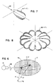
- the anisotropy of A( r - r ') is related to the gantry angle ⁇ and thus of the angle of incidence of the ray 28 at r '. If the gantry angles ⁇ at which the patient 17 is irradiated are predetermined, a multidirection convolution kernel B( r - r '), shown in Fig. 8, may be created from weighted superimposition of the kernels A( r - r ').
- Equation (7) substantially simplifies the calculation of dose from terma but still requires a convolution for each voxel r times the total number of voxels r ' to calculate the dose over the entire patient volume.
- the kernel B( r - r ') for an external radiation source 12 is a complex function of: (1) beam hardening of a polyenergetic x-ray beam (i.e., the effect of the filtration of the patient 17 in increasing the proportion of high frequency or high energy radiation components), (2) the number of rays 28 crossing each voxel, and (3) exponential attenuation by the patient mass.
- this first factor is neglected because it is an effect smaller than the attenuation problem.
- the photon energy spectrum in the patient 17 may be assumed to be the same as that of the external radiation source 12. This simplification is not required, however, and it will be understood that beam hardening could be accurately accounted for by representing a photon energy spectrum by a finite number of separately convolved energy intervals.
- the second factor the difference in the number and orientation of rays 28 that cross each voxel, caused by the geometry of a finite number of gantry angles and the fan orientation of the beam 14, affect spatial invariance. Problems arising from the fan orientation of the beam (in contrast to a parallel beam geometry) are largely solved if there is a full rotation of the gantry 44. Errors resulting from the fact that irradiation is performed at only a finite number of gantry angles have been determined to be acceptable.
- the third factor affecting the assumption of spatial invariance is the attenuation of the medium. This affects the fractional contribution of the total terma from the beams at each gantry angle. Accordingly, in those steps of the planning procedure, as will be noted below, where accurate calculation of dose is critical, the dose distribution is calculated separately for each beam based on the attenuation of overlying voxels, such attenuation deduced from the parameters of the tomographic image. In this case the simplification of equation (8) may not be employed and repeated convolutions must be performed. In certain steps in the planning process, however, as will be noted, an estimate is sufficient and in these cases B( r - r ') is assumed to be spatially invariant and the dose calculated according to equation (8).
- This inversion requires that there be no significant "zeros" (typically at high frequencies) in the denominator term F ⁇ B( r - r ) ⁇ or more simply that the kernel B( r - r ') be spatially compact (i.e., the Fourier transform of a spatially compact kernel will have significant high frequency content). It has been determined by the present inventors that the kernels dictated for patients 17 are sufficiently compact to allow this Fourier deconvolution.
- this deconvolution to produce a terma map 82 giving the terma for each voxel r , from the desired dose map 66, is represented by process block 80.
- ⁇ / ⁇ may be estimated and considered a constant or actual ⁇ / ⁇ may be deduced from the tomographic scan data collected by means of the tomographic imaging system 11, (shown in Fig. 4). In this manner and as illustrated by process block 84 of Fig. 9, a fluence map 86 giving the fluence at each point of the terma map may be determined.
- ⁇ 0 ( ⁇ , ⁇ ) is the energy fluence for a given ray 28 as described by ⁇ ( ⁇ -r ⁇ r ) at the exit of the compensator 22 and serves to define the fluence profile of the compensator and ⁇ and ⁇ are the gantry angle and the offset angles of the ray 28 as previously described.
- the exponential term represents the attenuation of the ray 28 from the exit of the compensator 22 to the voxel r caused by the mass of the patient 17
- ⁇ / ⁇ ( r ) is the attenuation for each voxel r along the ray 28
- ⁇ ( r ) is the density of each voxel r
- SSD( ⁇ , ⁇ ) is the distance between the exit of the compensator 22 and the surface of the patient 17
- r ⁇ is a unit vector along r (where the origin of r is now assumed to be the center of rotation of the gantry 45)
- p is the perpendicular distance from the gantry's center of rotation 45 and the ray 28.
- the vector t is simply a vector along the ray 28 to provide an integration variable.
- the fluence at each voxel r is related to the fluence of the radiation beam 14 emitted from the compensator 22 by equation (11).
- the density and attenuation of each voxel r , ⁇ / ⁇ ( r ) and ⁇ ( r ) are assumed to be constant and the fan beam of radiation is approximated by a parallel beam, hence SSD 2 ( ⁇ , ⁇ )
- 2 1
- the fluence map 86 may be "reverse" back projected (i.e. projected) by projector 85 to determine a fluence profile to be produced by the external-source necessary to generate the desired fluence map and hence dose.
- ⁇ 0 ( ⁇ , ⁇ ) ⁇ ⁇ ⁇ ( r ) ⁇ ( r ) ⁇ (p- r ⁇ r ) + 2 t ⁇ ( ⁇ ( r )e + ⁇ / ⁇ ( r ) ⁇ ( r ) ⁇ (p- r ⁇ r )d t
- Equation (13) The projection of equation (13) is represented by projector 85 in Fig. 9.
- the projection process for the purpose of computing fluence profiles for the compensator 22, differs in a fundamental way from the simple inverse of tomographic back projection. The difference is primarily In a concern for the sharpness in the transition of the dose between the irradiated tumorous tissue 68 and the healthy tissue 70. Sharpness in this transition region reduces the irradiation of healthy tissue 70 and is preferred over actual fidelity of the dose to the desired dose map 66.
- This prefilter 88 serves to increase the high frequency content of the fluence map 86 and thus to aid in rapid transition of dose at the tumor/non-tumor interface.
- this prefilter 88 is similar to the filter used in tomographic imaging's "filtered" back projection. That is, like tomographic imaging, the filter de-emphasizes the low frequency components of the projection in producing image data.
- other prefilters may be applied to correct for the use of the radially symmetric kernel (equation (6)) in computing the dose map from the terma map composed from the fluence profile
- the generation of a fluence map and the calculation of the fluence profiles need not be performed as discrete steps but may be accomplished by a direct projection of the dose map with appropriate filtering.
- the filtering is accomplished by a "fast inversion filter" which combines in projection space the operation of deconvolution and ramp filtration.
- the fluence profile calculations of block 78 including the deconvolver 80, the fluence calculator 84, the prefilter 88 which includes any projection space filter (such as a ramp filter, a fast inversion filter followed by truncation of zeros), and the projector 85 thus produce fluence profiles which together create an estimated treatment sinogram 87' from the desired dose map 66.
- the fluence profile calculator 78 may use the Fourier convolution of equation (9) in the estimate of the fluence profiles at this stage, accepting minor inaccuracies in that process, to be corrected at a later stage, as will be described below.
- the fluence profile calculator 78 converts the desired dose map 66 to an estimated treatment sinogram 87', however the fluence profiles of this estimated treatment sinogram 87' may not be used to control the compensator 22 because, in general, the estimated treatment sinogram 87 will include positive and negative values of fluence. Only positive values of fluence are-physically realizable by the compensator 22; a negative value of fluence would represent a ray 28 that absorbed radiation along its path which is physically unrealizable.
- the fluence values of the estimated treatment sinogram 87' are truncated to positive fluence values 89.
- the estimated treatment sinogram 87' no longer produces the desired dose map.
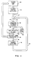
- the amount of error resulting from the truncation producing the positive fluence profiles 89 is determined by back projecting the positive fluence values 89 to an actual dose map 90 deviating from the desired dose map 66.
- This back projection is accomplished by computing a fluence map from the positive fluence values 89 per equation (11) and a terma map per equation (4) and then convolving the terma map with the kernel per equation (7) to establish the actual dose map 90 per process block 92 of Fig. 11.
- the projection of a fluence profile onto a patient 17 to compute a dose map may be performed by a number of other procedures known to those of ordinary skill in the art.
- the actual dose map 90 is compared to the desired dose map 66 to produce residual dose map 96 as indicated by process block 94.
- the comparison subtracts from the values of each voxel r of the actual dose map 90, the greater of: a) the corresponding value of desired dose map 66, or b) a predetermined upper dose constraint.
- the predetermined upper dose constraint is a threshold number that is deemed an acceptable dose to tumorous tissue 68.
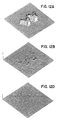
- the result of this comparison process 94 is to produce a residual dose map 96 shown in Fig 12(a).
- This residual dose map 96 is then, again, operated on by the fluence profile calculator 78 (in lieu of the desired dose map 66) to produce an error fluence profile 98 (in lieu of the estimated treatment sinogram 87).
- a thus produced error fluence profile 98 is subtracted by subtracter 100 from the estimated treatment sinogram 87' to produce a new estimated treatment sinogram 87.
- this new estimated treatment sinogram 87 is repeatedly operated on by process block 88, 92, 94 and 78 for a predetermined number of iterations, the magnitude of the error fluence profile 98 values decreasing with each iteration as shown in Figs. 12(b)-(d) until a suitably low error fluence profile 98 is obtained.
- the new estimated fluence profile 87 is then truncated per process block 88 to produce a final sinogram 91 for use in controlling the compensator 21 as previously described.
- dose maps obtained by the present invention corresponding to a desired dose map 66 of Fig. 5(a) are shown after: one iteration (Fig. 5 b)); two iterations (Fig. 5(c)); and ten iterations (Fig. 5(d)).
- the variations in dose in the target volume shown in Fig. 5(d) are plus or minus 2% about the predetermined upper limit of 1,000 cGy.
Landscapes
- Health & Medical Sciences (AREA)
- Engineering & Computer Science (AREA)
- Life Sciences & Earth Sciences (AREA)
- Physics & Mathematics (AREA)
- Biomedical Technology (AREA)
- High Energy & Nuclear Physics (AREA)
- General Health & Medical Sciences (AREA)
- Nuclear Medicine, Radiotherapy & Molecular Imaging (AREA)
- Radiology & Medical Imaging (AREA)
- Animal Behavior & Ethology (AREA)
- Pathology (AREA)
- Public Health (AREA)
- Veterinary Medicine (AREA)
- Medical Informatics (AREA)
- General Engineering & Computer Science (AREA)
- Optics & Photonics (AREA)
- Biophysics (AREA)
- Spectroscopy & Molecular Physics (AREA)
- Heart & Thoracic Surgery (AREA)
- Molecular Biology (AREA)
- Surgery (AREA)
- Theoretical Computer Science (AREA)
- Pulmonology (AREA)
- Radiation-Therapy Devices (AREA)
Abstract
Description


Claims (15)
- For use in a radiation therapy machine having a radiation source (12) for producing a radiation beam (14') directed toward a patient (17) at an angle (α) of a support gantry (44), the beam including a plurality of adjacent rays (28), a compensator (22) comprising:a plurality of radiation attenuating leaves (30);a rack (26) positioned generally between the radiation source and the patient and having a plurality of adjacent sleeves (24) for guiding the leaves (30) between a closed state within the radiation beam, each leaf (30) thus occluding one ray (28) of the beam, and an open state outside of the radiation beam to allow unobstructed passage of the ray; andmotivation means (32-35) for independently moving each leaf between the open and closed state; characterised in thattiming means (51,52) communicating with the motivation means for controlling the ratio of the period of time during which each leaf (30) is in the closed state to the period during which each leaf is in the open state to control the average energy fluence of each ray of the beam.
- A compensator according to claim 1, characterised in that the motivation means is a plurality of pneumatic cylinders (32) having pistons moved by air pressure and connected by linkages (34) to individual leaves (30) to move the leaves with movement of the pistons.
- A compensator according to claim 1 or 2, characterised in that the beam (14') diverges from a focal spot in a fan shape and the leaves (30) are wedge shaped to have adjacent faces defining planes intersecting a common line (20) through the focal spot.
- A compensator according to claim 1, 2 or 3, characterised in that the motivation means (32-35) slides the leaves (30) into and out of the sleeves (24) along guide rails (36) on each side of the leaves and in that the leaves include notches (38) for receiving the guide rails to reduce the space between the leaves in the leaves' closed state.
- A compensator according to claim 4, characterised in that the sleeves include an alignment guide (42) and in that the leaves are received in the alignment guide when moved to the closed state, the alignment guide having means to accurately position the leaves with respect to the rack and each other when they are in the closed state.
- A compensator according to any preceding claim, characterised in that the timing means (51) receives a value indicating the gantry angle (α) and changes each ratio of open to closed state for each leaf (30) as a function of this angle (α).
- A radiation therapy device having a radiation source (12) for producing a radiation beam (14') directed toward a volume of a patient (17) at a plurality of angles (α) of a support gantry (44), the beam including a plurality of adjacent rays, the fluence of each ray together defining a fluence profile, a compensator according to any preceding claim, and a therapy planning apparatus (78) comprising:an input means (66) for receiving a desired dose map of desired radiation doses within the volume of the patent;a deconvolution means (80) for producing a terma map, corresponding to the desired dose map, indicating energy release values and locations in the volume that with scatter, would produce the dose of the desired dose map;a fluence calculator (84) receiving the terma map and for determining the fluence of the rays at the locations to produce a fluence map; anda projection means (85) receiving the fluence values and combining the fluence values to produce the fluence profile corresponding to the desired dose map.
- A radiation therapy device according to claim 7, wherein the therapy planning apparatus includes:a back-projector (92) receiving the fluence profile and estimating the actual dose map produced;a residual dose calculator (94) for comparing the desired dose map to the actual dose map to produce a residual dose map; andan iteration means (78) for recalculating the fluence profile based on an error fluence profile produced from the residual dose map.
- A radiation therapy device according to claim 8, wherein the therapy planning apparatus is characterised in that the residual dose calculator (94) produces the residual dose map by comparing from the actual dose map with the desired dose map.
- A radiation therapy device according to claim 8, wherein the therapy planning apparatus is characterised in that the iteration means (78) provides residual dose map to the deconvolution means (80) and the fluence calculator (84) to calculate the error fluence profile in the same manner as the fluence profile is calculated from the desired dose map and in that the fluence profile is recalculated by subtracting the error fluence profile from the fluence profile.
- A radiation therapy device according to any one of claims 7 to 10, wherein the therapy planning apparatus is characterised in that the deconvolution means (80) produces the terma map by calculating the inverse Fourier transform of the ratio of the Fourier transform of the desired dose map devised by the Fourier transform of a kernel representing the spreading of the radiation from each location.
- A radiation therapy device according to any one of claims 7 to 11, wherein the therapy planning apparatus is characterised in that the deconvolution means, fluence calculator and projection means are implemented by convolving a fast inversion filter with a projection of the desired dose map, the fast inversion filter incorporating the convolution kernel for deducing the terma map.
- A radiation therapy device according to claim 12, where the kernel reflects the spreading caused by radiation beams at a plurality of predetermined gantry angles.
- A radiation therapy device according to any one of claims 7 to 13, wherein the therapy planning apparatus includes a pre-filter (88) for filtering the fluence map prior to the projection by the projection means (85).
- A radiation therapy device according to any one of claims 7 to 14, wherein the therapy planning apparatus includes a second input means for receiving an attenuation map of the volume and in that the fluence calculator produces a fluence map based on the attenuation map.
Applications Claiming Priority (2)
| Application Number | Priority Date | Filing Date | Title |
|---|---|---|---|
| US854521 | 1992-03-19 | ||
| US07/854,521 US5317616A (en) | 1992-03-19 | 1992-03-19 | Method and apparatus for radiation therapy |
Publications (3)
| Publication Number | Publication Date |
|---|---|
| EP0561533A2 EP0561533A2 (en) | 1993-09-22 |
| EP0561533A3 EP0561533A3 (en) | 1994-03-02 |
| EP0561533B1 true EP0561533B1 (en) | 1998-06-10 |
Family
ID=25318921
Family Applications (1)
| Application Number | Title | Priority Date | Filing Date |
|---|---|---|---|
| EP93301672A Expired - Lifetime EP0561533B1 (en) | 1992-03-19 | 1993-03-05 | Apparatus for radiation therapy |
Country Status (11)
| Country | Link |
|---|---|
| US (4) | US5317616A (en) |
| EP (1) | EP0561533B1 (en) |
| JP (1) | JP3522300B2 (en) |
| KR (1) | KR100273183B1 (en) |
| AT (1) | ATE167071T1 (en) |
| AU (1) | AU661640B2 (en) |
| CA (1) | CA2091275C (en) |
| DE (1) | DE69319010T2 (en) |
| IL (1) | IL104896A (en) |
| MX (1) | MX9301495A (en) |
| NZ (1) | NZ247042A (en) |
Families Citing this family (192)
| Publication number | Priority date | Publication date | Assignee | Title |
|---|---|---|---|---|
| US5394452A (en) * | 1992-03-19 | 1995-02-28 | Wisconsin Alumni Research Foundation | Verification system for radiation therapy |
| US5317616A (en) * | 1992-03-19 | 1994-05-31 | Wisconsin Alumni Research Foundation | Method and apparatus for radiation therapy |
| US5596619A (en) * | 1992-08-21 | 1997-01-21 | Nomos Corporation | Method and apparatus for conformal radiation therapy |
| EP0702839B1 (en) * | 1993-06-09 | 1999-02-17 | Wisconsin Alumni Research Foundation | Radiation therapy machine for producing a desired fluence profile |
| US5418827A (en) * | 1993-06-18 | 1995-05-23 | Wisconsin Alumino Research Foundation | Method for radiation therapy planning |
| DE69529857T2 (en) * | 1994-03-25 | 2004-01-08 | Kabushiki Kaisha Toshiba, Kawasaki | Radiotherapy System |
| US5513238A (en) * | 1994-10-11 | 1996-04-30 | Radionics, Inc. | Automatic planning for radiation dosimetry |
| US5668371A (en) * | 1995-06-06 | 1997-09-16 | Wisconsin Alumni Research Foundation | Method and apparatus for proton therapy |
| US5818902A (en) * | 1996-03-01 | 1998-10-06 | Elekta Ab | Intensity modulated arc therapy with dynamic multi-leaf collimation |
| US5602892A (en) * | 1996-03-21 | 1997-02-11 | Llacer; Jorge | Method for optimization of radiation therapy planning |
| US6038283A (en) * | 1996-10-24 | 2000-03-14 | Nomos Corporation | Planning method and apparatus for radiation dosimetry |
| US6005919A (en) | 1996-10-25 | 1999-12-21 | Radionics, Inc. | Jaw and circular collimator |
| EP0892966A1 (en) * | 1997-01-14 | 1999-01-27 | Edholm, Paul | Technique and arrangement for tomographic imaging |
| CN1052919C (en) * | 1997-03-15 | 2000-05-31 | 深圳奥沃国际科技发展有限公司 | Three-dimensional irradiation tech. and equipment with charged particle having Bragg peak character |
| US5834526A (en) * | 1997-07-11 | 1998-11-10 | Wu; Huey S. | Expandable hollow particles |
| US6052430A (en) * | 1997-09-25 | 2000-04-18 | Siemens Medical Systems, Inc. | Dynamic sub-space intensity modulation |
| IL121866A (en) | 1997-09-29 | 2000-11-21 | Ein Gal Moshe | Multiple layer multileaf collimator |
| US6636622B2 (en) | 1997-10-15 | 2003-10-21 | Wisconsin Alumni Research Foundation | Method and apparatus for calibration of radiation therapy equipment and verification of radiation treatment |
| US6393096B1 (en) | 1998-05-27 | 2002-05-21 | Nomos Corporation | Planning method and apparatus for radiation dosimetry |
| US6128366A (en) * | 1998-07-08 | 2000-10-03 | Siemens Medical Systems, Inc. | Dosimetry error reduction for optimized static intensity modulation |
| DE69937238T2 (en) | 1998-08-06 | 2008-07-10 | Wisconsin Alumni Research Foundation, Madison | TEST SYSTEM FOR RADIO THERAPY |
| WO2000007669A1 (en) | 1998-08-06 | 2000-02-17 | Wisconsin Alumni Research Foundation | Delivery modification system for radiation therapy |
| US6167114A (en) * | 1998-08-10 | 2000-12-26 | Siemens Medical Systems, Inc. | System and method for calculating scatter radiation including a collimator thickness |
| US6320938B1 (en) | 1998-10-28 | 2001-11-20 | F & L Medical Products | Method of X-ray protection during diagnostic CT imaging |
| DE19904972A1 (en) * | 1999-02-06 | 2000-08-17 | Deutsches Krebsforsch | Contour collimator for radiation therapy |
| DE19907098A1 (en) * | 1999-02-19 | 2000-08-24 | Schwerionenforsch Gmbh | Ion beam scanning system for radiation therapy e.g. for tumor treatment, uses energy absorption device displaced transverse to ion beam path via linear motor for altering penetration depth |
| WO2000059576A1 (en) | 1999-04-02 | 2000-10-12 | Wisconsin Alumni Research Foundation | Megavoltage computed tomography during radiotherapy |
| US6459769B1 (en) | 1999-05-03 | 2002-10-01 | Sherwood Services Ag | Movable miniature multi-leaf collimator |
| US6319189B1 (en) | 1999-09-13 | 2001-11-20 | Isotron, Inc. | Methods for treating solid tumors using neutron therapy |
| US6352500B1 (en) | 1999-09-13 | 2002-03-05 | Isotron, Inc. | Neutron brachytherapy device and method |
| US6817995B1 (en) | 2000-04-20 | 2004-11-16 | Isotron ,Inc. | Reinforced catheter connector and system |
| US6791090B2 (en) | 2000-05-17 | 2004-09-14 | Koninklijke Philips Electronics N.V. | Compton deconvolution camera |
| UA63038C2 (en) * | 2000-07-05 | 2004-01-15 | Muradin Abubekirovych Kumakhov | Method for radiation therapy of cancer, method for detecting localization of cancer, and device for its realization |
| CA2314794A1 (en) * | 2000-08-01 | 2002-02-01 | Dimitre Hristov | Apparatus for lesion or organ localization |
| US6381304B1 (en) | 2000-08-17 | 2002-04-30 | S&S X-Ray Products, Inc. | Machinable plastic compensator filter |
| US6463122B1 (en) * | 2000-08-21 | 2002-10-08 | Bio-Imaging Resource, Inc. | Mammography of computer tomography for imaging and therapy |
| US6497645B1 (en) | 2000-08-28 | 2002-12-24 | Isotron, Inc. | Remote afterloader |
| JP2002210029A (en) | 2001-01-19 | 2002-07-30 | Mitsubishi Electric Corp | Radiation therapy equipment |
| US7046831B2 (en) | 2001-03-09 | 2006-05-16 | Tomotherapy Incorporated | System and method for fusion-aligned reprojection of incomplete data |
| US6661870B2 (en) | 2001-03-09 | 2003-12-09 | Tomotherapy Incorporated | Fluence adjustment for improving delivery to voxels without reoptimization |
| US7054413B2 (en) * | 2001-03-15 | 2006-05-30 | Siemens Medical Solutions Usa, Inc. | Rotatable multi-element beam shaping device |
| US7853312B2 (en) * | 2001-06-07 | 2010-12-14 | Varian Medical Systems, Inc. | Seed localization system for use in an ultrasound system and method of using the same |
| EP2145650A1 (en) * | 2001-08-24 | 2010-01-20 | Mitsubishi Heavy Industries, Ltd. | Radiation treatment apparatus |
| JP3977623B2 (en) * | 2001-10-18 | 2007-09-19 | 株式会社東芝 | X-ray computed tomography system |
| DE10151987C2 (en) * | 2001-10-22 | 2003-11-06 | Fraunhofer Ges Forschung | Preparation of the selection of control variables for a dose distribution of a radiation device to be set in time and space |
| US6907282B2 (en) * | 2001-11-09 | 2005-06-14 | Siemens Medical Solutions Usa, Inc. | Intensity map resampling for multi-leaf collimator compatibility |
| FR2834179A1 (en) * | 2001-12-24 | 2003-06-27 | Chabunda Christophe Mwanza | Medical generation radio scanned image having odd number x-rays three phase beam producing using helix beam sweep with beams spaced central radiator object transmitting/producing four dimensions received signals |
| US7016522B2 (en) * | 2002-01-15 | 2006-03-21 | Siemens Medical Solutions Usa, Inc. | Patient positioning by video imaging |
| US8406844B2 (en) * | 2002-03-06 | 2013-03-26 | Tomotherapy Incorporated | Method for modification of radiotherapy treatment delivery |
| US7289599B2 (en) * | 2002-10-04 | 2007-10-30 | Varian Medical Systems Technologies, Inc. | Radiation process and apparatus |
| US7945021B2 (en) | 2002-12-18 | 2011-05-17 | Varian Medical Systems, Inc. | Multi-mode cone beam CT radiotherapy simulator and treatment machine with a flat panel imager |
| ATE411075T1 (en) * | 2003-01-30 | 2008-10-15 | Koninkl Philips Electronics Nv | RECONSTRUCTION OF LOCAL PATIENT DOSES IN COMPUTER TOMOGRAPHY |
| US20040254448A1 (en) * | 2003-03-24 | 2004-12-16 | Amies Christopher Jude | Active therapy redefinition |
| GB0310596D0 (en) * | 2003-05-08 | 2003-06-11 | Cancer Res Inst | Method and apparatus for producing an intensity modulated beam of radiation |
| WO2004103457A2 (en) * | 2003-05-14 | 2004-12-02 | Washington University In St.Louis | Enhanced micro-radiation therapy and a method of micro-irradiating biological systems |
| JP2007525249A (en) * | 2003-06-02 | 2007-09-06 | フォックス・チェイス・キャンサー・センター | High energy continuous energy ion selection system, ion therapy system, and ion therapy facility |
| US7778691B2 (en) * | 2003-06-13 | 2010-08-17 | Wisconsin Alumni Research Foundation | Apparatus and method using synchronized breathing to treat tissue subject to respiratory motion |
| US7343030B2 (en) * | 2003-08-05 | 2008-03-11 | Imquant, Inc. | Dynamic tumor treatment system |
| US7254215B2 (en) * | 2003-10-28 | 2007-08-07 | Ge Medical Systems Global Technology Company, Llc | Systems and methods for reducing radiation dosage |
| AU2005216070B2 (en) * | 2004-02-20 | 2012-01-19 | University Of Florida Research Foundation, Inc. | System for delivering conformal radiation therapy while simultaneously imaging soft tissue |
| US7672705B2 (en) * | 2004-07-19 | 2010-03-02 | Resonant Medical, Inc. | Weighted surface-to-surface mapping |
| CA2574675C (en) * | 2004-07-20 | 2015-11-24 | Resonant Medical Inc. | Calibrating imaging devices |
| US7729744B2 (en) * | 2004-07-20 | 2010-06-01 | Resonant Medical, Inc. | Verifying lesion characteristics using beam shapes |
| GB2418336A (en) * | 2004-09-17 | 2006-03-22 | Elekta Ab | Radiotherapy device and scanner |
| ATE506011T1 (en) * | 2004-09-20 | 2011-05-15 | Resonant Medical Inc | RADIOTHERAPY TREATMENT MONITORING USING ULTRASOUND |
| US20060072849A1 (en) * | 2004-09-27 | 2006-04-06 | Siemens Medical Solutions Usa, Inc. | Multi-leaf collimator position sensing |
| DE102004057726B4 (en) * | 2004-11-30 | 2010-03-18 | Siemens Ag | Medical examination and treatment facility |
| ES2330936T3 (en) * | 2004-12-23 | 2009-12-17 | Nucletron B.V. | PROCEDURE AND DEVICE FOR CALCULATING THE DISTRIBUTION OF THE RADIATION DOSE FOR A RADIATION TREATMENT SYSTEM TO SUBMIT THE BODY OF AN ANIMAL TO RADIOTHERAPY. |
| US7957507B2 (en) * | 2005-02-28 | 2011-06-07 | Cadman Patrick F | Method and apparatus for modulating a radiation beam |
| GB2424163A (en) * | 2005-03-10 | 2006-09-13 | Elekta Ab | Radiotherapeutic apparatus utilising helical motion of the source relative to the patient |
| US20070003010A1 (en) * | 2005-04-29 | 2007-01-04 | Varian Medical Systems Technologies, Inc. | Radiation systems with imaging capability |
| US8232535B2 (en) * | 2005-05-10 | 2012-07-31 | Tomotherapy Incorporated | System and method of treating a patient with radiation therapy |
| DE102005022540B4 (en) * | 2005-05-17 | 2007-07-05 | Siemens Ag | Method for minimizing image artifacts and medical imaging system |
| CA2616138A1 (en) * | 2005-07-22 | 2007-02-01 | Tomotherapy Incorporated | System and method of monitoring the operation of a medical device |
| US7839972B2 (en) | 2005-07-22 | 2010-11-23 | Tomotherapy Incorporated | System and method of evaluating dose delivered by a radiation therapy system |
| CA2616309A1 (en) * | 2005-07-22 | 2007-02-01 | Tomotherapy Incorporated | Method of and system for predicting dose delivery |
| EP1907058B1 (en) | 2005-07-22 | 2015-06-24 | TomoTherapy, Inc. | Method of placing constraints on a deformation map and system for implementing same |
| EP1907061A2 (en) * | 2005-07-22 | 2008-04-09 | Tomotherapy, Inc. | System and method of remotely directing radiation therapy treatment |
| CA2616316A1 (en) | 2005-07-22 | 2007-02-01 | Tomotherapy Incorporated | Method and system for adapting a radiation therapy treatment plan based on a biological model |
| AU2006272742A1 (en) * | 2005-07-22 | 2007-02-01 | Tomotherapy Incorporated | System and method of delivering radiation therapy to a moving region of interest |
| KR20080039916A (en) | 2005-07-22 | 2008-05-07 | 토모테라피 인코포레이티드 | Systems and methods for performing radiation therapy on moving areas of interest |
| US7609809B2 (en) | 2005-07-22 | 2009-10-27 | Tomo Therapy Incorporated | System and method of generating contour structures using a dose volume histogram |
| JP2009502257A (en) | 2005-07-22 | 2009-01-29 | トモセラピー・インコーポレーテッド | Method and system for evaluating delivered dose |
| WO2007014093A2 (en) | 2005-07-22 | 2007-02-01 | Tomotherapy Incorporated | Method and system for processing data relating to a radiation therapy treatment plan |
| US8442287B2 (en) * | 2005-07-22 | 2013-05-14 | Tomotherapy Incorporated | Method and system for evaluating quality assurance criteria in delivery of a treatment plan |
| JP2009502255A (en) | 2005-07-22 | 2009-01-29 | トモセラピー・インコーポレーテッド | Method and system for assessing quality assurance criteria in the delivery of treatment plans |
| US20090041200A1 (en) * | 2005-07-23 | 2009-02-12 | Tomotherapy Incorporated | Radiation therapy imaging and delivery utilizing coordinated motion of jaws, gantry, and couch |
| KR20080044250A (en) | 2005-07-23 | 2008-05-20 | 토모테라피 인코포레이티드 | Imaging and Implementation of Radiation Therapy Using Combined Movements of Gantry and Treatment Table |
| WO2007012185A1 (en) * | 2005-07-25 | 2007-02-01 | Karl Otto | Methods and apparatus for the planning and delivery of radiation treatments |
| US7880154B2 (en) | 2005-07-25 | 2011-02-01 | Karl Otto | Methods and apparatus for the planning and delivery of radiation treatments |
| DE102005034912B4 (en) * | 2005-07-26 | 2007-10-04 | Siemens Ag | Particle therapy system, method for determining control parameters of such a therapy system, radiotherapy planning device and irradiation method |
| CN100574827C (en) * | 2005-08-25 | 2009-12-30 | 深圳市海博科技有限公司 | radiotherapy device |
| WO2007028237A1 (en) * | 2005-09-06 | 2007-03-15 | Resonant Medical Inc. | System and method for patient setup for radiotherapy treatment |
| US7242749B2 (en) * | 2005-11-15 | 2007-07-10 | General Electric Company | Methods and systems for dynamic pitch helical scanning |
| US20070270627A1 (en) * | 2005-12-16 | 2007-11-22 | North American Scientific | Brachytherapy apparatus for asymmetrical body cavities |
| US8137256B2 (en) * | 2005-12-16 | 2012-03-20 | Portola Medical, Inc. | Brachytherapy apparatus |
| US8929621B2 (en) * | 2005-12-20 | 2015-01-06 | Elekta, Ltd. | Methods and systems for segmentation and surface matching |
| US20070147579A1 (en) * | 2005-12-23 | 2007-06-28 | De Man Bruno K B | Method and system for radiographic imaging with organ-based radiation profile prescription |
| WO2007084789A2 (en) * | 2006-01-20 | 2007-07-26 | Wisconsin Alumni Research Foundation | Method and apparatus for low dose computed tomography |
| WO2007106815A2 (en) * | 2006-03-14 | 2007-09-20 | University Of Notre Dame Du Lac | Methods and apparatus for hardware based radiation dose calculation |
| US7634307B2 (en) * | 2006-03-30 | 2009-12-15 | Spinal Generations, Llc | Method and apparatus for treatment of discogenic pain |
| US20090080602A1 (en) * | 2006-08-03 | 2009-03-26 | Kenneth Brooks | Dedicated breast radiation imaging/therapy system |
| US20080043910A1 (en) * | 2006-08-15 | 2008-02-21 | Tomotherapy Incorporated | Method and apparatus for stabilizing an energy source in a radiation delivery device |
| US7555101B2 (en) * | 2006-08-23 | 2009-06-30 | Siemens Medical Solutions Usa, Inc. | High-energy photon detector |
| US9451928B2 (en) | 2006-09-13 | 2016-09-27 | Elekta Ltd. | Incorporating internal anatomy in clinical radiotherapy setups |
| WO2008058089A2 (en) * | 2006-11-03 | 2008-05-15 | North American Scientific, Inc. | Brachytherapy device having seed tubes with individually-settable tissue spacings |
| JP2008173182A (en) * | 2007-01-16 | 2008-07-31 | Mitsubishi Heavy Ind Ltd | Radiation irradiation method and radiotherapy apparatus controller |
| WO2008106483A1 (en) * | 2007-02-27 | 2008-09-04 | Wisconsin Alumni Research Foundation | Ion radiation therapy system with distal gradient tracking |
| EP2114529B1 (en) * | 2007-02-27 | 2011-06-08 | Wisconsin Alumni Research Foundation | Heavy ion radiation therapy system with stair-step modulation |
| US9006677B2 (en) * | 2007-02-27 | 2015-04-14 | Wisconsin Alumni Research Foundation | Fan beam modulator for ion beams providing continuous intensity modulation |
| WO2008106496A1 (en) * | 2007-02-27 | 2008-09-04 | Wisconsin Alumni Research Foundation | Ion radiation therapy system with variable beam resolution |
| WO2008106488A1 (en) | 2007-02-27 | 2008-09-04 | Wisconsin Alumni Research Foundation | Ion radiation therapy system having magnetic fan beam former |
| US8129701B2 (en) * | 2007-02-27 | 2012-03-06 | Al-Sadah Jihad H | Areal modulator for intensity modulated radiation therapy |
| WO2008106492A1 (en) * | 2007-02-27 | 2008-09-04 | Wisconsin Alumni Research Foundation | Scanning aperture ion beam modulator |
| US7856082B2 (en) * | 2007-02-27 | 2010-12-21 | Wisconsin Alumni Research Foundation | System and method for optimization of a radiation therapy plan in the presence of motion |
| US8093568B2 (en) * | 2007-02-27 | 2012-01-10 | Wisconsin Alumni Research Foundation | Ion radiation therapy system with rocking gantry motion |
| US7714309B2 (en) * | 2007-02-27 | 2010-05-11 | Wisconsin Alumni Research Foundation | Phantom for ion range detection |
| USRE46953E1 (en) | 2007-04-20 | 2018-07-17 | University Of Maryland, Baltimore | Single-arc dose painting for precision radiation therapy |
| US10531858B2 (en) | 2007-07-20 | 2020-01-14 | Elekta, LTD | Methods and systems for guiding the acquisition of ultrasound images |
| CA2693351C (en) | 2007-07-20 | 2017-06-13 | Resonant Medical Inc. | Methods and systems for compensating for changes in anatomy of radiotherapy patients |
| US8135198B2 (en) | 2007-08-08 | 2012-03-13 | Resonant Medical, Inc. | Systems and methods for constructing images |
| WO2009032927A1 (en) * | 2007-09-04 | 2009-03-12 | Tomotherapy Incorporated | Patient support device |
| EP2214582A2 (en) * | 2007-10-25 | 2010-08-11 | Tomotherapy Incorporated | Method for adapting fractionation of a radiation therapy dose |
| US7706912B2 (en) * | 2007-11-30 | 2010-04-27 | Caterpillar Inc. | Orifice formation control system |
| US20090202045A1 (en) * | 2008-02-12 | 2009-08-13 | Varian Medical Systems Technologies, Inc. | Treatment booth for radiation therapy |
| GB2457483A (en) * | 2008-02-15 | 2009-08-19 | Elekta Ab | Multi-leaf collimator |
| CA2716598A1 (en) * | 2008-03-04 | 2009-09-11 | Tomotherapy Incorporated | Method and system for improved image segmentation |
| US8017915B2 (en) | 2008-03-14 | 2011-09-13 | Reflexion Medical, Inc. | Method and apparatus for emission guided radiation therapy |
| US8189738B2 (en) | 2008-06-02 | 2012-05-29 | Elekta Ltd. | Methods and systems for guiding clinical radiotherapy setups |
| EP2323555B1 (en) * | 2008-07-31 | 2016-04-27 | Analogic Corporation | Fluid transfer for radiation treatment apparatus |
| US8803910B2 (en) * | 2008-08-28 | 2014-08-12 | Tomotherapy Incorporated | System and method of contouring a target area |
| US8363784B2 (en) * | 2008-08-28 | 2013-01-29 | Tomotherapy Incorporated | System and method of calculating dose uncertainty |
| WO2010102068A2 (en) * | 2009-03-03 | 2010-09-10 | Tomotherapy Incorporated | System and method of optimizing a heterogeneous radiation dose to be delivered to a patient |
| WO2010120534A1 (en) | 2009-03-31 | 2010-10-21 | Whitten Matthew R | System and method for radiation therapy treatment planning using a memetic optimization algorithm |
| WO2010141583A2 (en) * | 2009-06-02 | 2010-12-09 | Mayo Foundation For Medical Education And Research | System and method for dose verification radiotherapy |
| US10542962B2 (en) | 2009-07-10 | 2020-01-28 | Elekta, LTD | Adaptive radiotherapy treatment using ultrasound |
| US9061141B2 (en) * | 2009-09-29 | 2015-06-23 | Tomotherapy Incorporated | Patient support device with low attenuation properties |
| US8401148B2 (en) * | 2009-10-30 | 2013-03-19 | Tomotherapy Incorporated | Non-voxel-based broad-beam (NVBB) algorithm for intensity modulated radiation therapy dose calculation and plan optimization |
| JP4911373B2 (en) * | 2009-11-26 | 2012-04-04 | 横河電機株式会社 | X-ray measuring device |
| US20110172526A1 (en) | 2010-01-12 | 2011-07-14 | Martin Lachaine | Feature Tracking Using Ultrasound |
| US9248316B2 (en) | 2010-01-12 | 2016-02-02 | Elekta Ltd. | Feature tracking using ultrasound |
| US20110201918A1 (en) * | 2010-02-12 | 2011-08-18 | Elekta Ab (Publ) | Radiotherapy and imaging apparatus |
| US20110201920A1 (en) * | 2010-02-12 | 2011-08-18 | Elekta Ab (Publ) | Radiotherapy and imaging apparatus |
| US9694205B2 (en) | 2010-02-12 | 2017-07-04 | Elekta Ab (Publ) | Radiotherapy and imaging apparatus |
| US9289627B2 (en) | 2010-06-22 | 2016-03-22 | Varian Medical Systems International Ag | System and method for estimating and manipulating estimated radiation dose |
| KR101090386B1 (en) * | 2010-09-17 | 2011-12-07 | 주식회사 인피니트헬스케어 | Apparatus and Evaluation Method for Radiation Treatment Plan |
| US8873710B2 (en) * | 2011-03-07 | 2014-10-28 | Sloan-Kettering Institute For Cancer Research | Multi-source radiation system and method for interwoven radiotherapy and imaging |
| US9283403B2 (en) | 2011-03-31 | 2016-03-15 | Reflexion Medical, Inc. | Systems and methods for use in emission guided radiation therapy |
| US8218718B1 (en) * | 2011-06-01 | 2012-07-10 | Elekta Ab (Publ) | Radiotherapy and imaging methods and apparatus |
| JP5931394B2 (en) * | 2011-10-07 | 2016-06-08 | 株式会社東芝 | X-ray diagnostic apparatus and dose distribution data generation method |
| DE102011087590B3 (en) | 2011-12-01 | 2013-06-06 | Siemens Aktiengesellschaft | Contour collimator with an X-ray impermeable liquid and associated method |
| DE102012220750B4 (en) | 2012-02-08 | 2015-06-03 | Siemens Aktiengesellschaft | Contour collimator with a magnetic, X-ray absorbing liquid and associated method |
| DE102012201856B4 (en) | 2012-02-08 | 2015-04-02 | Siemens Aktiengesellschaft | Contour collimator and adaptive filter with electroactive polymer elements and associated method |
| US10561861B2 (en) | 2012-05-02 | 2020-02-18 | Viewray Technologies, Inc. | Videographic display of real-time medical treatment |
| US10029118B2 (en) * | 2012-07-31 | 2018-07-24 | University Of Iowa Research Foundation | Advanced rotating-shield brachytherapy and planning of the same |
| JP6382208B2 (en) | 2012-10-26 | 2018-08-29 | ビューレイ・テクノロジーズ・インコーポレイテッドViewRay Technologies, Inc. | System and computer program product |
| WO2014133849A2 (en) * | 2013-02-26 | 2014-09-04 | Accuray Incorporated | Electromagnetically actuated multi-leaf collimator |
| JP5805689B2 (en) * | 2013-03-08 | 2015-11-04 | 株式会社モリタ製作所 | X-ray CT imaging apparatus and X-ray CT imaging method |
| US8971491B2 (en) | 2013-03-13 | 2015-03-03 | Wisconsin Alumni Research Foundation | System and method for improved radiosurgery collimation |
| US9446263B2 (en) | 2013-03-15 | 2016-09-20 | Viewray Technologies, Inc. | Systems and methods for linear accelerator radiotherapy with magnetic resonance imaging |
| DE102013215807B4 (en) * | 2013-08-09 | 2025-12-18 | Siemens Healthineers Ag | Methods for capturing projections during a spiral scan, methods for image production and multi-slice computed tomography device |
| US9661734B2 (en) | 2014-02-27 | 2017-05-23 | ETM Electromatic, Inc. | Linear accelerator system with stable interleaved and intermittent pulsing |
| US11083074B2 (en) | 2014-02-27 | 2021-08-03 | ETM Electromatic, Inc. | Scanning linear accelerator system having stable pulsing at multiple energies and doses |
| US10737122B2 (en) * | 2014-02-27 | 2020-08-11 | ETM Electromatic, Inc. | Self-shielded image guided radiation oncology system |
| CN107924730B (en) | 2015-06-10 | 2021-09-28 | 反射医疗公司 | High bandwidth binary multileaf collimator design |
| CN108367160A (en) | 2015-11-24 | 2018-08-03 | 优瑞技术公司 | Collimation of radiation beams system and method |
| CN109310879A (en) | 2016-03-02 | 2019-02-05 | 优瑞技术公司 | Particle Therapy Using Magnetic Resonance Imaging |
| CN109152928B (en) | 2016-03-09 | 2021-05-28 | 反射医疗公司 | Method and system for calculating a fluence map for radiation therapy |
| JP7098539B2 (en) | 2016-06-22 | 2022-07-11 | ビューレイ・テクノロジーズ・インコーポレイテッド | Magnetic resonance imaging |
| US10806409B2 (en) | 2016-09-23 | 2020-10-20 | Varian Medical Systems International Ag | Medical systems with patient supports |
| CN110248604B (en) | 2016-11-15 | 2023-07-21 | 反射医疗公司 | Radiation Therapy Patient Platform |
| WO2018093849A1 (en) | 2016-11-15 | 2018-05-24 | Reflexion Medical, Inc. | Methods for radiation delivery in emission-guided radiotherapy |
| WO2018093933A1 (en) | 2016-11-15 | 2018-05-24 | Reflexion Medical, Inc. | System for emission-guided high-energy photon delivery |
| RU2019121943A (en) | 2016-12-13 | 2021-01-15 | Вьюрэй Текнолоджиз, Инк. | SYSTEMS AND METHODS OF RADIOTHERAPY |
| WO2018183748A1 (en) | 2017-03-30 | 2018-10-04 | Reflexion Medical, Inc. | Radiation therapy systems and methods with tumor tracking |
| JP7672126B2 (en) | 2017-07-11 | 2025-05-07 | リフレクション メディカル, インコーポレイテッド | Method for PET detector afterglow management - Patents.com |
| CN111148471B (en) | 2017-08-09 | 2023-08-22 | 反射医疗公司 | Systems and methods for fault detection in shot-guided radiation therapy |
| US11369806B2 (en) | 2017-11-14 | 2022-06-28 | Reflexion Medical, Inc. | Systems and methods for patient monitoring for radiotherapy |
| JP7127126B2 (en) | 2017-12-06 | 2022-08-29 | ビューレイ・テクノロジーズ・インコーポレイテッド | Radiation therapy system, method and software |
| CN119701229A (en) | 2018-02-13 | 2025-03-28 | 反射医疗公司 | Beam station treatment planning and radiation delivery method |
| CN108785873A (en) * | 2018-04-11 | 2018-11-13 | 西安大医数码科技有限公司 | It is a kind of rotatably to focus radiotherapy head, radiotherapy equipment and system |
| CN108478941B (en) | 2018-04-28 | 2021-04-27 | 西安大医集团股份有限公司 | radiotherapy device |
| WO2019210456A1 (en) | 2018-05-02 | 2019-11-07 | Shenzhen United Imaging Healthcare Co., Ltd. | Systems and methods for generating radiation treatment plan |
| WO2019210455A1 (en) | 2018-05-02 | 2019-11-07 | Shanghai United Imaging Healthcare Co., Ltd. | Radiation systems for radition treatment and imaging |
| US11209509B2 (en) | 2018-05-16 | 2021-12-28 | Viewray Technologies, Inc. | Resistive electromagnet systems and methods |
| CN113082558B (en) * | 2018-08-24 | 2023-02-21 | 西安大医集团股份有限公司 | A source carrier, radiation source device and radiotherapy system |
| US10888713B2 (en) * | 2018-12-28 | 2021-01-12 | Varian Medical Systems, Inc. | Multileaf collimator with alternating trapezoidal leaf geometry design |
| WO2020257338A1 (en) * | 2019-06-17 | 2020-12-24 | Reflexion Medical, Inc. | Adaptive focus collimation of x-ray beams |
| GB2596575B (en) | 2020-07-01 | 2023-04-19 | Elekta ltd | An imaging system for a radiotherapy device |
| JP2023536662A (en) | 2020-08-07 | 2023-08-28 | リフレクション メディカル, インコーポレイテッド | Multi-sensor guided radiation therapy |
| WO2022098794A1 (en) | 2020-11-04 | 2022-05-12 | Reflexion Medical, Inc. | Methods for tumor tracking |
| CA3244427A1 (en) | 2021-12-27 | 2023-07-06 | Reflexion Medical, Inc. | Methods for radiation delivery quality assurance |
Family Cites Families (21)
| Publication number | Priority date | Publication date | Assignee | Title |
|---|---|---|---|---|
| NL6816451A (en) * | 1968-11-19 | 1970-05-21 | ||
| US3783251A (en) * | 1970-11-27 | 1974-01-01 | Varian Associates | Computer assisted radiation therapy machine |
| DE2613620A1 (en) * | 1976-03-30 | 1977-10-13 | Siemens Ag | IRRADIATION SYSTEM FOR IONIZING RADIATION |
| US4247774A (en) | 1978-06-26 | 1981-01-27 | The United States Of America As Represented By The Department Of Health, Education And Welfare | Simultaneous dual-energy computer assisted tomography |
| US4233519A (en) * | 1979-06-18 | 1980-11-11 | Varian Associates, Inc. | Radiation therapy apparatus having retractable beam stopper |
| DE3010780A1 (en) * | 1980-03-20 | 1981-09-24 | Siemens AG, 1000 Berlin und 8000 München | RAY DIAGNOSTIC DEVICE |
| JPS59111738A (en) * | 1982-12-16 | 1984-06-28 | 株式会社東芝 | X-ray tomographic apparatus |
| NL8501795A (en) * | 1985-06-21 | 1987-01-16 | Optische Ind De Oude Delft Nv | APPARATUS AND METHOD FOR SLITTLE RADIOGRAPHY WITH DIFFERENT VENT RADIATION ENERGIES. |
| US4905268A (en) * | 1985-10-25 | 1990-02-27 | Picker International, Inc. | Adjustable off-focal aperture for x-ray tubes |
| US4660799A (en) * | 1986-01-29 | 1987-04-28 | Butland Edward H | Load support structure |
| US4754147A (en) * | 1986-04-11 | 1988-06-28 | Michigan State University | Variable radiation collimator |
| DE3616141A1 (en) * | 1986-05-14 | 1987-11-19 | Siemens Ag | Contour collimator for radiation therapy (radiotherapy, X-ray therapy) |
| DE3621868A1 (en) * | 1986-06-30 | 1988-01-14 | Siemens Ag | X-RAY DIAGNOSTIC DEVICE WITH A DISC |
| US4868843A (en) * | 1986-09-10 | 1989-09-19 | Varian Associates, Inc. | Multileaf collimator and compensator for radiotherapy machines |
| GB2211710A (en) * | 1987-10-28 | 1989-07-05 | Philips Nv | Multileaf collimator |
| EP0371303B1 (en) * | 1988-11-29 | 1994-04-27 | Varian International AG. | Radiation therapy apparatus |
| US4998268A (en) * | 1989-02-09 | 1991-03-05 | James Winter | Apparatus and method for therapeutically irradiating a chosen area using a diagnostic computer tomography scanner |
| JPH0787835B2 (en) * | 1990-06-27 | 1995-09-27 | 株式会社東芝 | X-ray tomography system |
| JP2593576B2 (en) * | 1990-07-31 | 1997-03-26 | 株式会社東芝 | Radiation positioning device |
| US5394452A (en) * | 1992-03-19 | 1995-02-28 | Wisconsin Alumni Research Foundation | Verification system for radiation therapy |
| US5317616A (en) * | 1992-03-19 | 1994-05-31 | Wisconsin Alumni Research Foundation | Method and apparatus for radiation therapy |
-
1992
- 1992-03-19 US US07/854,521 patent/US5317616A/en not_active Expired - Lifetime
-
1993
- 1993-03-01 IL IL10489693A patent/IL104896A/en not_active IP Right Cessation
- 1993-03-02 NZ NZ247042A patent/NZ247042A/en not_active IP Right Cessation
- 1993-03-05 DE DE69319010T patent/DE69319010T2/en not_active Expired - Lifetime
- 1993-03-05 AT AT93301672T patent/ATE167071T1/en not_active IP Right Cessation
- 1993-03-05 EP EP93301672A patent/EP0561533B1/en not_active Expired - Lifetime
- 1993-03-09 CA CA002091275A patent/CA2091275C/en not_active Expired - Lifetime
- 1993-03-17 MX MX9301495A patent/MX9301495A/en unknown
- 1993-03-18 JP JP05898393A patent/JP3522300B2/en not_active Expired - Lifetime
- 1993-03-18 AU AU35323/93A patent/AU661640B2/en not_active Expired
- 1993-03-18 KR KR1019930004146A patent/KR100273183B1/en not_active Expired - Lifetime
- 1993-06-09 US US08/071,742 patent/US5548627A/en not_active Expired - Lifetime
- 1993-06-09 US US08/071,741 patent/US5442675A/en not_active Expired - Lifetime
-
1994
- 1994-02-02 US US08/191,243 patent/US5528650A/en not_active Expired - Fee Related
Also Published As
| Publication number | Publication date |
|---|---|
| DE69319010T2 (en) | 1998-10-08 |
| AU661640B2 (en) | 1995-07-27 |
| EP0561533A2 (en) | 1993-09-22 |
| ATE167071T1 (en) | 1998-06-15 |
| AU3532393A (en) | 1993-09-23 |
| US5317616A (en) | 1994-05-31 |
| JPH067464A (en) | 1994-01-18 |
| DE69319010D1 (en) | 1998-07-16 |
| CA2091275C (en) | 2003-01-07 |
| US5548627A (en) | 1996-08-20 |
| US5442675A (en) | 1995-08-15 |
| EP0561533A3 (en) | 1994-03-02 |
| CA2091275A1 (en) | 1993-09-20 |
| MX9301495A (en) | 1994-02-28 |
| KR100273183B1 (en) | 2001-03-02 |
| US5528650A (en) | 1996-06-18 |
| KR930019234A (en) | 1993-10-18 |
| IL104896A0 (en) | 1993-07-08 |
| IL104896A (en) | 1997-02-18 |
| JP3522300B2 (en) | 2004-04-26 |
| NZ247042A (en) | 1996-02-27 |
Similar Documents
| Publication | Publication Date | Title |
|---|---|---|
| US5317616A (en) | Method and apparatus for radiation therapy | |
| US5724400A (en) | Radiation therapy system with constrained rotational freedom | |
| US5661773A (en) | Interface for radiation therapy machine | |
| EP0702839B1 (en) | Radiation therapy machine for producing a desired fluence profile | |
| US5351280A (en) | Multi-leaf radiation attenuator for radiation therapy | |
| US6560311B1 (en) | Method for preparing a radiation therapy plan | |
| EP0656797B1 (en) | Apparatus and method for radiation therapy planning | |
| JP4082759B2 (en) | Method and apparatus for adjusting radiation output | |
| Fiorino et al. | Dynamic beam modulation by using a single computer-controlled absorber |
Legal Events
| Date | Code | Title | Description |
|---|---|---|---|
| PUAI | Public reference made under article 153(3) epc to a published international application that has entered the european phase |
Free format text: ORIGINAL CODE: 0009012 |
|
| AK | Designated contracting states |
Kind code of ref document: A2 Designated state(s): AT BE CH DE DK ES FR GB GR IE IT LI LU MC NL PT SE |
|
| PUAL | Search report despatched |
Free format text: ORIGINAL CODE: 0009013 |
|
| AK | Designated contracting states |
Kind code of ref document: A3 Designated state(s): AT BE CH DE DK ES FR GB GR IE IT LI LU MC NL PT SE |
|
| 17P | Request for examination filed |
Effective date: 19940505 |
|
| 17Q | First examination report despatched |
Effective date: 19951207 |
|
| GRAG | Despatch of communication of intention to grant |
Free format text: ORIGINAL CODE: EPIDOS AGRA |
|
| GRAG | Despatch of communication of intention to grant |
Free format text: ORIGINAL CODE: EPIDOS AGRA |
|
| GRAG | Despatch of communication of intention to grant |
Free format text: ORIGINAL CODE: EPIDOS AGRA |
|
| GRAH | Despatch of communication of intention to grant a patent |
Free format text: ORIGINAL CODE: EPIDOS IGRA |
|
| GRAH | Despatch of communication of intention to grant a patent |
Free format text: ORIGINAL CODE: EPIDOS IGRA |
|
| GRAA | (expected) grant |
Free format text: ORIGINAL CODE: 0009210 |
|
| AK | Designated contracting states |
Kind code of ref document: B1 Designated state(s): AT BE CH DE DK ES FR GB GR IE IT LI LU MC NL PT SE |
|
| PG25 | Lapsed in a contracting state [announced via postgrant information from national office to epo] |
Ref country code: LI Free format text: LAPSE BECAUSE OF FAILURE TO SUBMIT A TRANSLATION OF THE DESCRIPTION OR TO PAY THE FEE WITHIN THE PRESCRIBED TIME-LIMIT Effective date: 19980610 Ref country code: IT Free format text: LAPSE BECAUSE OF FAILURE TO SUBMIT A TRANSLATION OF THE DESCRIPTION OR TO PAY THE FEE WITHIN THE PRESCRIBED TIME-LIMIT;WARNING: LAPSES OF ITALIAN PATENTS WITH EFFECTIVE DATE BEFORE 2007 MAY HAVE OCCURRED AT ANY TIME BEFORE 2007. THE CORRECT EFFECTIVE DATE MAY BE DIFFERENT FROM THE ONE RECORDED. Effective date: 19980610 Ref country code: GR Free format text: LAPSE BECAUSE OF NON-PAYMENT OF DUE FEES Effective date: 19980610 Ref country code: ES Free format text: THE PATENT HAS BEEN ANNULLED BY A DECISION OF A NATIONAL AUTHORITY Effective date: 19980610 Ref country code: CH Free format text: LAPSE BECAUSE OF FAILURE TO SUBMIT A TRANSLATION OF THE DESCRIPTION OR TO PAY THE FEE WITHIN THE PRESCRIBED TIME-LIMIT Effective date: 19980610 Ref country code: AT Free format text: LAPSE BECAUSE OF FAILURE TO SUBMIT A TRANSLATION OF THE DESCRIPTION OR TO PAY THE FEE WITHIN THE PRESCRIBED TIME-LIMIT Effective date: 19980610 |
|
| RAP1 | Party data changed (applicant data changed or rights of an application transferred) |
Owner name: WISCONSIN ALUMNI RESEARCH FOUNDATION |
|
| REF | Corresponds to: |
Ref document number: 167071 Country of ref document: AT Date of ref document: 19980615 Kind code of ref document: T |
|
| REG | Reference to a national code |
Ref country code: CH Ref legal event code: EP |
|
| REF | Corresponds to: |
Ref document number: 69319010 Country of ref document: DE Date of ref document: 19980716 |
|
| ET | Fr: translation filed | ||
| PG25 | Lapsed in a contracting state [announced via postgrant information from national office to epo] |
Ref country code: SE Free format text: LAPSE BECAUSE OF FAILURE TO SUBMIT A TRANSLATION OF THE DESCRIPTION OR TO PAY THE FEE WITHIN THE PRESCRIBED TIME-LIMIT Effective date: 19980910 Ref country code: DK Free format text: LAPSE BECAUSE OF FAILURE TO SUBMIT A TRANSLATION OF THE DESCRIPTION OR TO PAY THE FEE WITHIN THE PRESCRIBED TIME-LIMIT Effective date: 19980910 |
|
| PG25 | Lapsed in a contracting state [announced via postgrant information from national office to epo] |
Ref country code: PT Free format text: LAPSE BECAUSE OF FAILURE TO SUBMIT A TRANSLATION OF THE DESCRIPTION OR TO PAY THE FEE WITHIN THE PRESCRIBED TIME-LIMIT Effective date: 19980915 |
|
| REG | Reference to a national code |
Ref country code: IE Ref legal event code: FG4D |
|
| REG | Reference to a national code |
Ref country code: CH Ref legal event code: PL |
|
| PG25 | Lapsed in a contracting state [announced via postgrant information from national office to epo] |
Ref country code: LU Free format text: LAPSE BECAUSE OF NON-PAYMENT OF DUE FEES Effective date: 19990305 Ref country code: IE Free format text: LAPSE BECAUSE OF NON-PAYMENT OF DUE FEES Effective date: 19990305 |
|
| PLBE | No opposition filed within time limit |
Free format text: ORIGINAL CODE: 0009261 |
|
| STAA | Information on the status of an ep patent application or granted ep patent |
Free format text: STATUS: NO OPPOSITION FILED WITHIN TIME LIMIT |
|
| 26N | No opposition filed | ||
| PG25 | Lapsed in a contracting state [announced via postgrant information from national office to epo] |
Ref country code: MC Free format text: LAPSE BECAUSE OF NON-PAYMENT OF DUE FEES Effective date: 19990930 |
|
| REG | Reference to a national code |
Ref country code: IE Ref legal event code: MM4A |
|
| REG | Reference to a national code |
Ref country code: GB Ref legal event code: IF02 |
|
| PGFP | Annual fee paid to national office [announced via postgrant information from national office to epo] |
Ref country code: FR Payment date: 20120319 Year of fee payment: 20 |
|
| PGFP | Annual fee paid to national office [announced via postgrant information from national office to epo] |
Ref country code: BE Payment date: 20120328 Year of fee payment: 20 Ref country code: GB Payment date: 20120301 Year of fee payment: 20 |
|
| PGFP | Annual fee paid to national office [announced via postgrant information from national office to epo] |
Ref country code: DE Payment date: 20120404 Year of fee payment: 20 Ref country code: NL Payment date: 20120321 Year of fee payment: 20 |
|
| REG | Reference to a national code |
Ref country code: DE Ref legal event code: R071 Ref document number: 69319010 Country of ref document: DE |
|
| REG | Reference to a national code |
Ref country code: DE Ref legal event code: R071 Ref document number: 69319010 Country of ref document: DE |
|
| REG | Reference to a national code |
Ref country code: NL Ref legal event code: V4 Effective date: 20130305 |
|
| REG | Reference to a national code |
Ref country code: GB Ref legal event code: PE20 Expiry date: 20130304 |
|
| BE20 | Be: patent expired |
Owner name: WISCONSIN *ALUMNI RESEARCH FOUNDATION Effective date: 20130305 |
|
| PG25 | Lapsed in a contracting state [announced via postgrant information from national office to epo] |
Ref country code: GB Free format text: LAPSE BECAUSE OF EXPIRATION OF PROTECTION Effective date: 20130304 Ref country code: DE Free format text: LAPSE BECAUSE OF EXPIRATION OF PROTECTION Effective date: 20130306 |