EP0561528B1 - Braking system - Google Patents
Braking system Download PDFInfo
- Publication number
- EP0561528B1 EP0561528B1 EP93301598A EP93301598A EP0561528B1 EP 0561528 B1 EP0561528 B1 EP 0561528B1 EP 93301598 A EP93301598 A EP 93301598A EP 93301598 A EP93301598 A EP 93301598A EP 0561528 B1 EP0561528 B1 EP 0561528B1
- Authority
- EP
- European Patent Office
- Prior art keywords
- brake element
- shaft
- rotation
- impeller
- motor
- Prior art date
- Legal status (The legal status is an assumption and is not a legal conclusion. Google has not performed a legal analysis and makes no representation as to the accuracy of the status listed.)
- Expired - Lifetime
Links
- 229920001187 thermosetting polymer Polymers 0.000 claims description 5
- KXGFMDJXCMQABM-UHFFFAOYSA-N 2-methoxy-6-methylphenol Chemical group [CH]OC1=CC=CC([CH])=C1O KXGFMDJXCMQABM-UHFFFAOYSA-N 0.000 claims description 3
- 239000003365 glass fiber Substances 0.000 claims description 2
- 239000005011 phenolic resin Substances 0.000 claims description 2
- 229920001568 phenolic resin Polymers 0.000 claims description 2
- 238000004519 manufacturing process Methods 0.000 description 2
- 239000000463 material Substances 0.000 description 2
- 230000033228 biological regulation Effects 0.000 description 1
- 238000010276 construction Methods 0.000 description 1
- 238000006073 displacement reaction Methods 0.000 description 1
- 230000000694 effects Effects 0.000 description 1
- 239000000945 filler Substances 0.000 description 1
- 230000006698 induction Effects 0.000 description 1
- 239000012212 insulator Substances 0.000 description 1
- 239000002184 metal Substances 0.000 description 1
- 238000000034 method Methods 0.000 description 1
- 239000004033 plastic Substances 0.000 description 1
- 229920003023 plastic Polymers 0.000 description 1
Images



Classifications
-
- A—HUMAN NECESSITIES
- A01—AGRICULTURE; FORESTRY; ANIMAL HUSBANDRY; HUNTING; TRAPPING; FISHING
- A01D—HARVESTING; MOWING
- A01D34/00—Mowers; Mowing apparatus of harvesters
- A01D34/01—Mowers; Mowing apparatus of harvesters characterised by features relating to the type of cutting apparatus
- A01D34/412—Mowers; Mowing apparatus of harvesters characterised by features relating to the type of cutting apparatus having rotating cutters
- A01D34/63—Mowers; Mowing apparatus of harvesters characterised by features relating to the type of cutting apparatus having rotating cutters having cutters rotating about a vertical axis
- A01D34/67—Mowers; Mowing apparatus of harvesters characterised by features relating to the type of cutting apparatus having rotating cutters having cutters rotating about a vertical axis hand-guided by a walking operator
- A01D34/68—Mowers; Mowing apparatus of harvesters characterised by features relating to the type of cutting apparatus having rotating cutters having cutters rotating about a vertical axis hand-guided by a walking operator with motor driven cutters or wheels
- A01D34/6806—Driving mechanisms
- A01D34/6812—Braking or clutching mechanisms
-
- F—MECHANICAL ENGINEERING; LIGHTING; HEATING; WEAPONS; BLASTING
- F16—ENGINEERING ELEMENTS AND UNITS; GENERAL MEASURES FOR PRODUCING AND MAINTAINING EFFECTIVE FUNCTIONING OF MACHINES OR INSTALLATIONS; THERMAL INSULATION IN GENERAL
- F16D—COUPLINGS FOR TRANSMITTING ROTATION; CLUTCHES; BRAKES
- F16D67/00—Combinations of couplings and brakes; Combinations of clutches and brakes
- F16D67/02—Clutch-brake combinations
-
- A—HUMAN NECESSITIES
- A01—AGRICULTURE; FORESTRY; ANIMAL HUSBANDRY; HUNTING; TRAPPING; FISHING
- A01D—HARVESTING; MOWING
- A01D2101/00—Lawn-mowers
Definitions
- the present invention relates to an improved braking system which is particularly suitable for use with a powered rotary tool of the type in which a shaft is rotated about an axis by a motor, for example a lawn mower of the rotary type in which a blade and optionally an impeller are rotated about a common axis by a motor, which may be an electric motor or a petrol motor.
- a powered rotary tool of the type in which a shaft is rotated about an axis by a motor
- a motor for example a lawn mower of the rotary type in which a blade and optionally an impeller are rotated about a common axis by a motor, which may be an electric motor or a petrol motor.
- Braking systems which are currently available for use on mowers of this type include electromechanical systems which are spring loaded brake systems comprising a brake pad and a brake disc, the spring urging the pad and disc into braking contact and being opposed by the action of a solenoid.
- brakes of the type in which the magnetic field created in the rotor is used to hold a movable brake disc in an OFF position against the spring force while the motor is running have been proposed.
- the magnetic field is energised only when the motor is energised.
- Braking systems for electric motors which comprise an electromagnetically releasable spring actuated brake with a braking surface, a brake disc driven in rotation, a release device non-rotatably secured to the braking surface, and an armature mounted non-rotatably and so as to be capable of axial displacement between the brake disc and the release device, and biased by springs against the brake disc.
- Such braking systems have been disclosed in connection with motors having substantially horizontal mounted axles to be stopped.
- EP-A-0 288 348 A further braking system having the features contained in the preambles of Claims 1, 2 of the present patent is disclosed in EP-A-0 288 348 which relies on the inertia of the mower blade on starting and stopping of the motor to release and apply a brake.
- the construction of the braking system is relatively complex and thus relatively expensive to manufacture.
- the present invention provides braking system for a powered rotary tool comprising;
- the means for releasing the braking contact on start-up of the motor preferably comprises four equiangularly spaced pairs of co-operating ramp surfaces.
- the braking system according to the invention is particularly suitable for use with a lawn mower of the rotary type in which a blade and an impeller are rotated about an axis by a motor.
- the rotary lawn mower 110 comprises a deck 102 on which a series electric motor 104 is mounted.
- the motor 104 is provided with an output shaft 106 on which is fitted a blade 108 and impeller 112.
- a brake disc 114 is attached by means of screws 116 to the impeller 112.
- An adaptor 118 is securely fixed to the output shaft 106 and an assembly comprising the impeller 112 and disc 114, together with a drive insert 120 is slidably mounted on the output shaft 106, by means of the adaptor 118, so that the assembly is free to move in an axial direction relative to the shaft 106.
- the adaptor 118 is generally cylindrical in shape, with an annular flange 124 at the end remote from the output shaft 106.
- Four equiangularly spaced ramps 126 project from the upper surface of the annular flange 124, the height of the ramps increasing in the direction of rotation of the shaft 106.
- a spline 128 projects from cylindrical wall of the adaptor 118, extending from the ramp 126 to the end of the adaptor remote from the flange 124.
- the drive insert 120 is also generally cylindrical in shape and is similarly provided with an annular flange 130 at the end remote from the output shaft 106.
- ramp surfaces 132 are formed as recesses in the lower surface of the annular flange 130, the depth of the recesses increasing in the direction of rotation of the shaft 106.
- a groove 134 in the internal wall of the drive insert extends from the ramp surface 132 for the full length of the insert 120.
- the internal diameter of the drive insert 120 and the external diameter of the adaptor 118 are selected so that the adaptor 118 is received within the insert 120 as a sliding fit.
- the width of the grooves 134 in the insert 120 is greater than the width of the splines 128 in the adaptor 118, so that a limited amount of angular rotation of the adaptor 118 with respect to the insert 120 is possible.
- a brake friction housing 136 is secured to a mounting plate 138 which is itself secured to a housing 140 of the motor 104.
- Brake friction pads 142 are attached to an inner surface of the brake friction housing 136.
- a spring 144 is provided to urge the brake disc 114 downwardly into braking contact with the pads 142 on the brake friction housing 136.
- a cup washer 146 is mounted on the shaft 106 and clamped against the bearing of the housing 104 by the adaptor 118.
- the cup washer 146 rotates with the shaft, and has the function of compressing the spring 144 against the brake disc 114.
- the adaptor 118 In operation, as the motor 104 is energised, the adaptor 118 is driven by the output shaft 106 and begins to rotate. As the adaptor 118 begins to rotate, the ramp surfaces 126 engage with the ramp surfaces 132, and the drive insert 120 is pushed axially upwards against the action of the spring 144. The drive insert 120 lifts the brake disc 114 away from braking contact with the brake pads 124 on the brake friction housing 120.
- the splines 128 engage with the corresponding side walls of the grooves 134 and the drive insert 120, and hence the impeller 112 begins to rotate.
- the impeller 112 When the motor 104 is switched off, the impeller 112 is no longer driven by the output shaft 106 and the speed of rotation reduces sharply. This has the effect of reducing the pressure differential between the two surfaces of the impeller, equalising the rotational forces on the impeller.
- the force of the spring 144 is no longer opposed by the suction force generated by the rotating impeller 112 and thus urges the brake disc 114 and brake friction plate 136 into braking contact, thus braking the system.
- FIG. 4 and 5 An alternative embodiment of a braking system according to the invention is shown in Figures 4 and 5.
- the braking system shown in Figures 4 and 5 is similar in many respects to that of Figures 1 to 3, but differs therefrom in the design and detailed operation of the first and second brake elements.
- a brake housing 136 is secured to a mounting plate 138 which is itself secured to a housing 140 of the motor 104.
- a spring 144 is provided to urge a brake disc 114 downwardly into braking contact with the brake housing 136.
- a ring shaped friction element 150 is attached to, and movable with, the brake disc 114.
- the braking system is shown in the engaged position.
- the spring 144 is urging the brake disc 114, with attached friction element 150, into braking contact with the brake housing 136.
- the adaptor 118 is driven by the output shaft 106 and begins to rotate.
- the ramp surfaces 126 engage with the ramp surfaces 132, and the drive insert 120 is pushed axially upwards against the action of the spring 144.
- the drive insert 120 lifts the brake disc 114, with friction element 150, away from braking contact with the brake housing 136.
- the brake friction element 150 which is in the form of a ring is attached to the brake disc 114 by a suitable method of attachment, for example an interference fit, bonding or a screw thread.
- the brake housing 136 or, preferably the disc 114 may comprise a moulded thermoset plastics part, in particular moulded from a thermoset plastics material which is based on a phenolic resin, and is filled with a suitable filler, for example glass fibres, in order to improve its strength.
- the disc is moulded from a thermoset plastics material, and the housing is in metal, the disc can then act as heat insulator to reduce the transfer of heat from the brake contact area to the plastic impeller.
Landscapes
- Engineering & Computer Science (AREA)
- General Engineering & Computer Science (AREA)
- Life Sciences & Earth Sciences (AREA)
- Environmental Sciences (AREA)
- Mechanical Engineering (AREA)
- Harvester Elements (AREA)
- Braking Arrangements (AREA)
Description
- The present invention relates to an improved braking system which is particularly suitable for use with a powered rotary tool of the type in which a shaft is rotated about an axis by a motor, for example a lawn mower of the rotary type in which a blade and optionally an impeller are rotated about a common axis by a motor, which may be an electric motor or a petrol motor.
- For safety reasons, it is necessary to incorporate a braking system within the lawn mower, so that the blade and, where provided, the impeller are brought to a stop within a specified time. With the increased concern for safety, safety requirements are continually becoming more stringent, and it is now generally accepted that a stop time of less than 3 seconds is particularly desirable, and indeed is increasingly being required by statutory regulations in many countries.
- Braking systems which are currently available for use on mowers of this type include electromechanical systems which are spring loaded brake systems comprising a brake pad and a brake disc, the spring urging the pad and disc into braking contact and being opposed by the action of a solenoid.
- For mowers of the type driven by an induction motor, brakes of the type in which the magnetic field created in the rotor is used to hold a movable brake disc in an OFF position against the spring force while the motor is running have been proposed. In these systems, the magnetic field is energised only when the motor is energised.
- Braking systems for electric motors are also known, which comprise an electromagnetically releasable spring actuated brake with a braking surface, a brake disc driven in rotation, a release device non-rotatably secured to the braking surface, and an armature mounted non-rotatably and so as to be capable of axial displacement between the brake disc and the release device, and biased by springs against the brake disc. Such braking systems have been disclosed in connection with motors having substantially horizontal mounted axles to be stopped.
- In such braking systems, on energising the motor the axle moves to separate the brake disc from its corresponding braking surface. On de-activating the motor, the spring urges the brake disc back into contact with the braking surface.
- It is a disadvantage of the known electromechanical braking systems that they are expensive to manufacture and add significantly to the cost of each unit to which they are fitted. Where attempts have been made to reduce the cost of these systems by using part of the motor housing to provide part of the housing for the solenoid coil and spring, these systems only achieve a stop time in the order of 5 seconds, which is not sufficiently short to satisfy the more stringent safety requirements which require a stop time of less than 3 seconds.
- It would be possible to achieve stop times of less than 3 seconds by increasing the size of the brake disc, but this would lose part of the cost saving benefit.
- Known electromagnetically releasable spring actuated braking systems would not be suitable for use with a substantially vertical shaft, since the force generated by the magnetic field is not sufficient to hold the armature in its raised position under normal running conditions, after the initial surge observed when the motor is energised.
- A further braking system having the features contained in the preambles of Claims 1, 2 of the present patent is disclosed in EP-A-0 288 348 which relies on the inertia of the mower blade on starting and stopping of the motor to release and apply a brake. However, the construction of the braking system is relatively complex and thus relatively expensive to manufacture.
- It is an object of the present invention to provide a braking system suitable for a powered rotary tool, in which the above disadvantages are reduced or substantially obviated.
- The present invention provides braking system for a powered rotary tool comprising;
- a shaft which is adapted to be rotatably driven about an axis by a motor,
- a first brake element,
- engagement means between the shaft and the first brake element for rotatably driving the first brake element which engagement means allow a small amount of relative rotation between the shaft and the first braking element on start up of the motor,
- a second brake element which is restrained from rotation, resilient means which urge the first brake element in an axial direction into braking contact with the second brake element,
and - at least one pair of co-operating ramp surfaces, a first one of the or each pair of ramp surfaces being arranged for rotation with the shaft and the second one of the or each pair of ramp surfaces being arranged for rotation with the first brake element such that the first and second ramp surfaces co-operate to release the braking contact between the first brake element and the second brake element upon the relative rotation between the shaft and the first braking element on start up of the motor,
characterised in that the or each first ramp surface is located on an adaptor which is mounted for rotation with the shaft and the or each second ramp surface is located on a drive insert which is mounted for rotation with the first brake element and which is slideably mounted on the shaft by means of the adaptor. - The means for releasing the braking contact on start-up of the motor preferably comprises four equiangularly spaced pairs of co-operating ramp surfaces.
- The braking system according to the invention is particularly suitable for use with a lawn mower of the rotary type in which a blade and an impeller are rotated about an axis by a motor.
- The invention will now be further described with reference to the accompanying drawings, of which
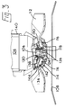
- Figure 1 is a general side elevation, partially in section, of a lawn mower comprising an embodiment of a braking system according to the invention;
- Figure 2 is an exploded view on an enlarged scale, of the braking system of Figure 1;
- Figure 3 is a side elevation, partially in section, of the braking system of Figures 1 and 2;
- Figure 4 is a side elevation, partially in section, of an alternative embodiment of a braking system according to the invention, in the braked position; and
- Figure 5 is a similar view to Figure 4, in the non-braked position.
- The
rotary lawn mower 110 comprises adeck 102 on which a serieselectric motor 104 is mounted. Themotor 104 is provided with anoutput shaft 106 on which is fitted ablade 108 andimpeller 112. Abrake disc 114 is attached by means ofscrews 116 to theimpeller 112. Anadaptor 118 is securely fixed to theoutput shaft 106 and an assembly comprising theimpeller 112 anddisc 114, together with adrive insert 120 is slidably mounted on theoutput shaft 106, by means of theadaptor 118, so that the assembly is free to move in an axial direction relative to theshaft 106. - As can be seen from Figure 2, the
adaptor 118 is generally cylindrical in shape, with anannular flange 124 at the end remote from theoutput shaft 106. Four equiangularly spacedramps 126 project from the upper surface of theannular flange 124, the height of the ramps increasing in the direction of rotation of theshaft 106. Associated with each of theramps 126, aspline 128 projects from cylindrical wall of theadaptor 118, extending from theramp 126 to the end of the adaptor remote from theflange 124. - As can also be seen from Figure 2, the
drive insert 120 is also generally cylindrical in shape and is similarly provided with anannular flange 130 at the end remote from theoutput shaft 106. Four equiangularly spacedramp surfaces 132 are formed as recesses in the lower surface of theannular flange 130, the depth of the recesses increasing in the direction of rotation of theshaft 106. Associated with each of theramp surfaces 132, agroove 134 in the internal wall of the drive insert extends from theramp surface 132 for the full length of theinsert 120. - The internal diameter of the drive insert 120 and the external diameter of the
adaptor 118 are selected so that theadaptor 118 is received within theinsert 120 as a sliding fit. The width of thegrooves 134 in theinsert 120 is greater than the width of thesplines 128 in theadaptor 118, so that a limited amount of angular rotation of theadaptor 118 with respect to theinsert 120 is possible. - A
brake friction housing 136 is secured to amounting plate 138 which is itself secured to ahousing 140 of themotor 104.Brake friction pads 142 are attached to an inner surface of thebrake friction housing 136. - A
spring 144 is provided to urge thebrake disc 114 downwardly into braking contact with thepads 142 on thebrake friction housing 136. - A
cup washer 146 is mounted on theshaft 106 and clamped against the bearing of thehousing 104 by theadaptor 118. The cup washer 146 rotates with the shaft, and has the function of compressing thespring 144 against thebrake disc 114. - In operation, as the
motor 104 is energised, theadaptor 118 is driven by theoutput shaft 106 and begins to rotate. As theadaptor 118 begins to rotate, theramp surfaces 126 engage with theramp surfaces 132, and thedrive insert 120 is pushed axially upwards against the action of thespring 144. The drive insert 120 lifts thebrake disc 114 away from braking contact with thebrake pads 124 on thebrake friction housing 120. - After the initial rotation, the
splines 128 engage with the corresponding side walls of thegrooves 134 and the drive insert 120, and hence theimpeller 112 begins to rotate. - As the speed of rotation increases, a pressure differential is built up due to the rotation of the
impeller 112, and the pressure on the motor side of theimpeller 112 falls sharply, tending to draw the assembly comprising theimpeller 112 andbrake disc 114 towards themotor 104 against the action of thespring 144. Theimpeller 112 andblade 108 are free to rotate. - When the
motor 104 is switched off, theimpeller 112 is no longer driven by theoutput shaft 106 and the speed of rotation reduces sharply. This has the effect of reducing the pressure differential between the two surfaces of the impeller, equalising the rotational forces on the impeller. The force of thespring 144 is no longer opposed by the suction force generated by the rotatingimpeller 112 and thus urges thebrake disc 114 andbrake friction plate 136 into braking contact, thus braking the system. - An alternative embodiment of a braking system according to the invention is shown in Figures 4 and 5. The braking system shown in Figures 4 and 5 is similar in many respects to that of Figures 1 to 3, but differs therefrom in the design and detailed operation of the first and second brake elements.
- As is shown in Figure 4, a
brake housing 136 is secured to amounting plate 138 which is itself secured to ahousing 140 of themotor 104. Aspring 144 is provided to urge abrake disc 114 downwardly into braking contact with thebrake housing 136. A ring shapedfriction element 150 is attached to, and movable with, thebrake disc 114. - In Figure 4, the braking system is shown in the engaged position. The
spring 144 is urging thebrake disc 114, with attachedfriction element 150, into braking contact with thebrake housing 136. - The operation of the braking system is as described above in connection with the embodiment shown in Figures 1 to 3. As the
motor 104 is energised, theadaptor 118 is driven by theoutput shaft 106 and begins to rotate. As theadaptor 118 begins to rotate, the ramp surfaces 126 engage with the ramp surfaces 132, and thedrive insert 120 is pushed axially upwards against the action of thespring 144. Thedrive insert 120 lifts thebrake disc 114, withfriction element 150, away from braking contact with thebrake housing 136. Thebrake friction element 150 which is in the form of a ring is attached to thebrake disc 114 by a suitable method of attachment, for example an interference fit, bonding or a screw thread. - In an alternative embodiment of a braking system according to the invention, the
brake housing 136 or, preferably thedisc 114, may comprise a moulded thermoset plastics part, in particular moulded from a thermoset plastics material which is based on a phenolic resin, and is filled with a suitable filler, for example glass fibres, in order to improve its strength. - Where the disc is moulded from a thermoset plastics material, and the housing is in metal, the disc can then act as heat insulator to reduce the transfer of heat from the brake contact area to the plastic impeller.
Claims (11)
- A braking system for a powered rotary tool comprising;a shaft (106) which is adapted to be rotatably driven about an axis by a motor (104),a first brake element (114),engagement means (128,134) between the shaft and the first brake element for rotatably driving the first brake element which engagement means allow a small amount of relative rotation between the shaft and the first braking element on start up of the motora second brake element (136) which is restrained from rotation,resilient means (144) which urge the first brake element in an axial direction into braking contact with the second brake element,
andat least one pair of co-operating ramp surfaces (126, 132) a first one (126) of the or each pair of ramp surfaces being arranged for rotation with the shaft and the second one (132) of the or each pair of ramp surfaces being arranged for rotation with the first brake element (114) such that the first and second ramp surfaces co-operate to release the braking contact between the first brake element and the second brake element upon the relative rotation between the shaft and the first braking element on start up of the motor
characterised in that the or each first ramp surface (126) is located on an adaptor (118) which is mounted for rotation with the shaft (106), and the or each second ramp surface (132) is located on a drive insert (120) which is mounted for rotation with the first brake element and which is slideably mounted on the shaft (106) by means of the adaptor (118). - A braking system for a lawn mower of the rotary type, comprising;a shaft (106) which is adapted to be rotatably driven about an axis by a motor (104),an impeller (112) which carries a first brake element (114),engagement means (128,134) between the shaft and the impeller for rotatably driving the impeller which engagement means allow a small amount of relative rotation between the shaft and the impeller on start up of the motor,a second brake element (136) which is restrained from rotation,resilient means (144) which urge the first brake element in an axial direction into braking contact with the second brake element,
andat least one pair of co-operating ramp surfaces (126, 132) a first one (126) of the or each pair of ramp surfaces being arranged for rotation with the shaft and the second one (132) of the or each pair of ramp surfaces being arranged for rotation with the impeller such that the first and second ramp surfaces co-operate to axially displace the impeller on start up of the motor in order to release the braking contact between the first brake element and the second brake element upon the relative rotation between the shaft and the impeller on start up of the motor,
characterised in that the or each first ramp surface (126) is located on an adaptor (118) which is mounted for rotation with the shaft (106), and the or each second ramp surface (132) is located on a drive insert (120) which is mounted for rotation with the impeller and which is slideably mounted on the output shaft by means of the adaptor (118). - A braking system according to claim 1 characterised in that the adaptor (118) and the drive insert (120) form the engagement means between the shaft and the first brake element which allow a small angle of relative rotation between the shaft and the first brake element on start up of the motor.
- A braking system according to claim 2 characterised in that the adaptor (118) and the drive insert (120) form the engagement means between the shaft and the impeller which allow a small angle of relative rotation between the shaft and the impeller on start up of the motor.
- A braking system according to any one of the preceding claims, characterised in that the first brake element (114) comprises a friction element (150).
- A braking system according to any one of claims 1 or claim 4, characterised in that the second brake element (136) comprises a friction element (142).
- A braking system according to any one of the preceding claims, characterised in that the adaptor and drive insert each carry four equiangularly spaced pairs of co-operating ramp surfaces (126, 132).
- A braking system according to any one of claims 1 to 7 characterised in that the first brake element (114) is a moulded thermoset plastic part.
- A braking system according to any one of claims 1 to 7 characterised in that the second brake element (136) comprises a moulded thermoset plastics part.
- A braking system according to any one of claims 1 to 7 characterised in that the first brake element (114) or the second brake element comprises a filled phenolic resin part.
- A braking system according to claim 10, characterised in that the phenolic resin is filled with glass fibre.
Applications Claiming Priority (2)
| Application Number | Priority Date | Filing Date | Title |
|---|---|---|---|
| GB929205611A GB9205611D0 (en) | 1992-03-14 | 1992-03-14 | Braking system |
| GB9205611 | 1992-03-14 |
Publications (2)
| Publication Number | Publication Date |
|---|---|
| EP0561528A1 EP0561528A1 (en) | 1993-09-22 |
| EP0561528B1 true EP0561528B1 (en) | 1997-05-02 |
Family
ID=10712149
Family Applications (1)
| Application Number | Title | Priority Date | Filing Date |
|---|---|---|---|
| EP93301598A Expired - Lifetime EP0561528B1 (en) | 1992-03-14 | 1993-03-03 | Braking system |
Country Status (5)
| Country | Link |
|---|---|
| US (1) | US5407400A (en) |
| EP (1) | EP0561528B1 (en) |
| CA (1) | CA2091189C (en) |
| DE (1) | DE69310253D1 (en) |
| GB (1) | GB9205611D0 (en) |
Cited By (1)
| Publication number | Priority date | Publication date | Assignee | Title |
|---|---|---|---|---|
| WO2012166123A1 (en) * | 2011-05-31 | 2012-12-06 | Husqvarna Consumer Outdoor Products N.A., Inc. | Light riding vehicle with varible friction drive |
Families Citing this family (12)
| Publication number | Priority date | Publication date | Assignee | Title |
|---|---|---|---|---|
| SE505313C2 (en) * | 1996-05-31 | 1997-08-04 | Fhp Elmotor Ab | Braking |
| US6615964B2 (en) * | 2000-07-28 | 2003-09-09 | Honda Giken Kogyo Kabushiki Kaisha | Friction member for a brake and clutch |
| DE10214419A1 (en) * | 2002-03-30 | 2003-10-30 | Ennepetaler Schneid Maehtech | Tool with at least one tool that can be driven by a motor and a brake that stops the tool |
| US6617728B1 (en) * | 2002-12-20 | 2003-09-09 | Chun Hsiang Wang | Motor synchronous excitation brake |
| TWI224178B (en) * | 2003-06-27 | 2004-11-21 | Benq Corp | Driving apparatus and self-brake mechanism thereof |
| US6740997B1 (en) * | 2003-08-19 | 2004-05-25 | Cheng Hsian Chen | Front brake of an electric motor |
| CN103168567B (en) * | 2011-12-22 | 2016-03-02 | 浙江三锋实业股份有限公司 | The dead-man's device of garden instrument |
| US9373987B2 (en) | 2013-09-11 | 2016-06-21 | Honda Motor Co., Ltd. | Integrated flywheels, systems and methods for electric generation and braking of a general purpose engine |
| ES2735997T3 (en) * | 2014-03-21 | 2019-12-23 | Ims Gear Se & Co Kgaa | Actuator Arrangement |
| JP6165091B2 (en) * | 2014-03-27 | 2017-07-19 | 本田技研工業株式会社 | Lawn mower blade mounting structure |
| CN110972722B (en) * | 2019-10-25 | 2021-10-26 | 浙江亚特电器有限公司 | a garden tool |
| US12329063B2 (en) | 2021-02-12 | 2025-06-17 | Techtronic Cordless Gp | Handle assembly for a power tool |
Family Cites Families (21)
| Publication number | Priority date | Publication date | Assignee | Title |
|---|---|---|---|---|
| GB878538A (en) * | 1959-03-25 | 1961-10-04 | Francesco Chiolerio | Automatic brake for winches and the like |
| US3731472A (en) * | 1972-03-27 | 1973-05-08 | Simplicity Mfg Co Inc | Rotary mower spindle brake |
| US3908344A (en) * | 1972-10-10 | 1975-09-30 | Int Harvester Co | Self actuating mechanism for braking a driven member upon discontinuation of drive thereto |
| US3994376A (en) * | 1973-04-25 | 1976-11-30 | International Harvester Company | Self actuating mechanism for braking a driven member upon discontinuating of drive thereto |
| US4037389A (en) * | 1974-07-05 | 1977-07-26 | Briggs & Stratton Corporation | Brake safety system for a power driven rotary mower |
| US3967438A (en) * | 1975-04-18 | 1976-07-06 | International Harvester Company | Rotary mower spindle assembly |
| JPS5225949A (en) * | 1975-08-23 | 1977-02-26 | Shimadzu Corp | Brake-loaded oil pressure motor |
| US4213521A (en) * | 1976-12-22 | 1980-07-22 | Warner Electric Brake & Clutch Company | Clutch-brake assembly for rotary implements |
| FR2411503A1 (en) * | 1977-12-06 | 1979-07-06 | Normandie Moteurs Electr | ROTATING ELECTRIC MACHINE WITH SELF-BRAKING ROTOR, AND APPARATUS WITH ROTARY CUTTING BODY, INCLUDING SUCH AN ELECTRIC MACHINE |
| JPS591466Y2 (en) * | 1978-02-02 | 1984-01-17 | 本田技研工業株式会社 | self-propelled lawn mower |
| US4351424A (en) * | 1980-05-14 | 1982-09-28 | The Murray Ohio Manufacturing Co. | Combined clutch and brake |
| US4306405A (en) * | 1980-08-07 | 1981-12-22 | Roper Corporation | Drive assembly for rotary mower or the like |
| DE3036091C2 (en) * | 1980-09-25 | 1986-01-30 | Hanning Elektro-Werke GmbH & Co, 4811 Oerlinghausen | Electric motor with automatic brake |
| US4362004A (en) * | 1980-11-24 | 1982-12-07 | Mtd Products Inc. | Brake and clutch mechanism |
| FR2508126A1 (en) * | 1981-06-22 | 1982-12-24 | Leroy Somer Moteurs | SAFETY BRAKING DEVICE INTERPOSED BETWEEN A MOTOR SHAFT AND A ROTATING WORKGROUP |
| US4466233A (en) * | 1982-09-30 | 1984-08-21 | Thesman Industries, Inc. | Mower drive assembly |
| US4730710A (en) * | 1983-10-11 | 1988-03-15 | Polaris Industries, Inc. | Clutch-brake assembly |
| GB8517216D0 (en) * | 1985-07-06 | 1985-08-14 | Lucas Ind Plc | Self-energising disc brakes |
| GB8517217D0 (en) * | 1985-07-06 | 1985-08-14 | Lucas Ind Plc | Self-energising disc brakes |
| FR2614377B3 (en) * | 1987-04-21 | 1989-07-21 | Peugeot Cycles | CLUTCH AND BRAKE DEVICE FOR DRIVING A ROTARY MEMBER SUCH AS A LAWNMOWER BLADE |
| US5033595A (en) * | 1990-06-08 | 1991-07-23 | Dana Corporation | Clutch/brake unit |
-
1992
- 1992-03-14 GB GB929205611A patent/GB9205611D0/en active Pending
-
1993
- 1993-03-03 EP EP93301598A patent/EP0561528B1/en not_active Expired - Lifetime
- 1993-03-03 DE DE69310253T patent/DE69310253D1/en not_active Expired - Lifetime
- 1993-03-08 CA CA002091189A patent/CA2091189C/en not_active Expired - Lifetime
- 1993-03-12 US US08/030,943 patent/US5407400A/en not_active Expired - Lifetime
Cited By (2)
| Publication number | Priority date | Publication date | Assignee | Title |
|---|---|---|---|---|
| WO2012166123A1 (en) * | 2011-05-31 | 2012-12-06 | Husqvarna Consumer Outdoor Products N.A., Inc. | Light riding vehicle with varible friction drive |
| US9445541B2 (en) | 2011-05-31 | 2016-09-20 | Husqvarna Ab | Light riding vehicle with variable friction drive |
Also Published As
| Publication number | Publication date |
|---|---|
| US5407400A (en) | 1995-04-18 |
| EP0561528A1 (en) | 1993-09-22 |
| GB9205611D0 (en) | 1992-04-29 |
| CA2091189C (en) | 2001-05-15 |
| CA2091189A1 (en) | 1993-09-15 |
| DE69310253D1 (en) | 1997-06-05 |
Similar Documents
| Publication | Publication Date | Title |
|---|---|---|
| CA2091189C (en) | Braking system | |
| CN109962570B (en) | Motor of scooter | |
| CA2072441C (en) | Lawn mower | |
| US5796192A (en) | Energy-saving electric drive for small vehicles | |
| JP4063527B2 (en) | Electric hand tools | |
| WO2000006896A3 (en) | Friction clutch bearing an electric machine rotor, in particular for a motor vehicle | |
| KR20120017072A (en) | Automotive Compact Pedal System | |
| EP0943831A3 (en) | Spring set centrifugally released brake | |
| US4926986A (en) | Centrifugal clutch for an actuator for rendering inoperative an automobile vehicle door latch | |
| CA1079209A (en) | Rotational rate of change sensor | |
| CA1096268A (en) | Speed responsive rotary coupling | |
| US4838391A (en) | Braking device | |
| CA2027442C (en) | Electromagnetic clutch | |
| US20040188217A1 (en) | Electromagnetic clutch | |
| EP1139545A2 (en) | Geared motor having worm and worm wheel | |
| EP0478398B1 (en) | Electromechanical control device with a centrifugal structure | |
| US8973721B2 (en) | Braking apparatus | |
| US3461994A (en) | Centrifugal clutch and brake | |
| US6707192B2 (en) | Electric motor with brakes | |
| US4542864A (en) | Brake device for coaxial reel tape recorders | |
| US4310083A (en) | Device for connecting a driving element to a driven element so as to be locked against mutual rotation, and for separating the same | |
| NL8302693A (en) | ELECTRIC MOTOR WITH A BRAKING DEVICE. | |
| CN218868748U (en) | Riding type mower with reverse gear cutting prevention device | |
| US5602436A (en) | Motor starting switch with adjustable running clearance | |
| EP0154440A2 (en) | Rotary flywheel skid sensing means for vehicle hydraulic braking systems |
Legal Events
| Date | Code | Title | Description |
|---|---|---|---|
| PUAI | Public reference made under article 153(3) epc to a published international application that has entered the european phase |
Free format text: ORIGINAL CODE: 0009012 |
|
| AK | Designated contracting states |
Kind code of ref document: A1 Designated state(s): DE FR GB SE |
|
| 17P | Request for examination filed |
Effective date: 19940226 |
|
| 17Q | First examination report despatched |
Effective date: 19950427 |
|
| GRAG | Despatch of communication of intention to grant |
Free format text: ORIGINAL CODE: EPIDOS AGRA |
|
| GRAH | Despatch of communication of intention to grant a patent |
Free format text: ORIGINAL CODE: EPIDOS IGRA |
|
| GRAH | Despatch of communication of intention to grant a patent |
Free format text: ORIGINAL CODE: EPIDOS IGRA |
|
| GRAA | (expected) grant |
Free format text: ORIGINAL CODE: 0009210 |
|
| AK | Designated contracting states |
Kind code of ref document: B1 Designated state(s): DE FR GB SE |
|
| PG25 | Lapsed in a contracting state [announced via postgrant information from national office to epo] |
Ref country code: FR Effective date: 19970502 |
|
| REF | Corresponds to: |
Ref document number: 69310253 Country of ref document: DE Date of ref document: 19970605 |
|
| PG25 | Lapsed in a contracting state [announced via postgrant information from national office to epo] |
Ref country code: SE Effective date: 19970802 |
|
| PG25 | Lapsed in a contracting state [announced via postgrant information from national office to epo] |
Ref country code: DE Effective date: 19970805 |
|
| EN | Fr: translation not filed | ||
| PLBE | No opposition filed within time limit |
Free format text: ORIGINAL CODE: 0009261 |
|
| STAA | Information on the status of an ep patent application or granted ep patent |
Free format text: STATUS: NO OPPOSITION FILED WITHIN TIME LIMIT |
|
| 26N | No opposition filed | ||
| REG | Reference to a national code |
Ref country code: GB Ref legal event code: IF02 |
|
| PGFP | Annual fee paid to national office [announced via postgrant information from national office to epo] |
Ref country code: GB Payment date: 20120326 Year of fee payment: 20 |
|
| REG | Reference to a national code |
Ref country code: GB Ref legal event code: PE20 Expiry date: 20130302 |
|
| PG25 | Lapsed in a contracting state [announced via postgrant information from national office to epo] |
Ref country code: GB Free format text: LAPSE BECAUSE OF EXPIRATION OF PROTECTION Effective date: 20130302 |