EP0561449A2 - Ceramic burner for a hot-blast stove of a blast furnace - Google Patents
Ceramic burner for a hot-blast stove of a blast furnace Download PDFInfo
- Publication number
- EP0561449A2 EP0561449A2 EP93200661A EP93200661A EP0561449A2 EP 0561449 A2 EP0561449 A2 EP 0561449A2 EP 93200661 A EP93200661 A EP 93200661A EP 93200661 A EP93200661 A EP 93200661A EP 0561449 A2 EP0561449 A2 EP 0561449A2
- Authority
- EP
- European Patent Office
- Prior art keywords
- burner
- duct
- central
- gas
- air
- Prior art date
- Legal status (The legal status is an assumption and is not a legal conclusion. Google has not performed a legal analysis and makes no representation as to the accuracy of the status listed.)
- Granted
Links
- 239000000919 ceramic Substances 0.000 title claims abstract description 19
- 238000005192 partition Methods 0.000 claims description 9
- 238000010276 construction Methods 0.000 claims description 3
- 238000000034 method Methods 0.000 claims description 3
- 238000002485 combustion reaction Methods 0.000 abstract description 10
- 239000007789 gas Substances 0.000 description 32
- 230000000694 effects Effects 0.000 description 5
- 239000000567 combustion gas Substances 0.000 description 3
- 229910000831 Steel Inorganic materials 0.000 description 1
- 238000013459 approach Methods 0.000 description 1
- 230000001419 dependent effect Effects 0.000 description 1
- 238000010438 heat treatment Methods 0.000 description 1
- 230000008092 positive effect Effects 0.000 description 1
- 230000001172 regenerating effect Effects 0.000 description 1
- 230000000630 rising effect Effects 0.000 description 1
- 239000010959 steel Substances 0.000 description 1
Images

Classifications
-
- C—CHEMISTRY; METALLURGY
- C21—METALLURGY OF IRON
- C21B—MANUFACTURE OF IRON OR STEEL
- C21B9/00—Stoves for heating the blast in blast furnaces
-
- F—MECHANICAL ENGINEERING; LIGHTING; HEATING; WEAPONS; BLASTING
- F23—COMBUSTION APPARATUS; COMBUSTION PROCESSES
- F23D—BURNERS
- F23D14/00—Burners for combustion of a gas, e.g. of a gas stored under pressure as a liquid
- F23D14/20—Non-premix gas burners, i.e. in which gaseous fuel is mixed with combustion air on arrival at the combustion zone
- F23D14/22—Non-premix gas burners, i.e. in which gaseous fuel is mixed with combustion air on arrival at the combustion zone with separate air and gas feed ducts, e.g. with ducts running parallel or crossing each other
-
- F—MECHANICAL ENGINEERING; LIGHTING; HEATING; WEAPONS; BLASTING
- F23—COMBUSTION APPARATUS; COMBUSTION PROCESSES
- F23D—BURNERS
- F23D2900/00—Special features of, or arrangements for burners using fluid fuels or solid fuels suspended in a carrier gas
- F23D2900/21—Burners specially adapted for a particular use
- F23D2900/21001—Burners specially adapted for a particular use for use in blast furnaces
Definitions
- the horizontal axis represents the height above the burner and the vertical axis represents the burn-out as a percentage of complete combustion.
- Curve 1 represents the burn-out characteristic of the known burner of EP-A-0306072; curve 2 represents that of the illustrated burner in accordance with the invention. Because of the "double" air mixing achieved in the burner of the invention, the maximum burn-out attained is higher (closer to 100%) and a higher burn-out degree is attained at a lower height above the burner.
- the CO content of the combusted gases which can be achieved with the known burner at a maximum burn-out is of the order of magnitude of 5,000 ppm CO. With the illustrated burner in accordance with the invention this fraction may be reduced to approximately 100 ppm CO.
Landscapes
- Engineering & Computer Science (AREA)
- Chemical & Material Sciences (AREA)
- Manufacturing & Machinery (AREA)
- Materials Engineering (AREA)
- Metallurgy (AREA)
- Organic Chemistry (AREA)
- Combustion & Propulsion (AREA)
- Mechanical Engineering (AREA)
- General Engineering & Computer Science (AREA)
- Gas Burners (AREA)
- Pre-Mixing And Non-Premixing Gas Burner (AREA)
Abstract
Description
- The invention relates to a ceramic gas burner for a hot-blast stove of a blast furnace. Typically, such a burner has central gas duct that opens into a central zone of a burner crown and side air ducts on both sides of the gas duct which also open in the central zone. The invention also relates to a method for operating such a ceramic burner.
- Hot blast stoves, which act as regenerative heat exchangers for the heating of blast air for a blast furnace, are well known. A burner as described above is known from European patent specification EP-A-0306072. In this known burner, the relative positioning of the outflow openings of the gas and air ducts, together with recesses formed by grooves in the long sides of the outflow openings, is intended to lower the point where the mixing turbulence is complete. This has a positive effect on the stability of the flame as well as the uniformity and completeness of the combustion of the combustion gas.
- The degree of completeness of combustion, the so-called burn-out, is dependent on the height above the burner at which maximum burn-out is achieved, that is to say that maximum burn-out is only achieved at a specific height above the burner. The trend of the burn-out as a function of the height above the burner may be imagined as a rising curve which approaches the maximum burn-out asymptotically.
- An object of the invention is to improve combustion characteristics, in particular it is sought that the curve of the relationship of burn-out and height above burner, becomes steeper; in other words it is desired that the maximum burn-out is to be attained at a lower height above the burner or that a higher degree of burn-out of the combustion gas is to be attained at the same height above the burner.
- In accordance with the invention there is provided a ceramic gas burner for a hot blast stove having a burner crown and gas and air ducts having respective discharge openings at said burner crown, said gas and air ducts comprising
a central gas duct;
at least two side air ducts which have their said discharge openings at respectively opposite sides of said discharge opening of said central gas duct; and
at least one central air duct having at least one said discharge opening within said central gas duct as seen in plan view. Suitably, the central gas duct extends vertically upwardly to its discharge opening, within the central gas duct. - It is preferable that the central air duct opens into central zone of the burner crown, at which the central gas duct and the side air ducts also open.
- Preferably the central air duct provides a T-shape flow path for air, having an upwardly extending leg portion of the T-shape and at the top thereof arm portions of the T-shape extending laterally in opposite directions to respective discharge openings. With this design of the burner, a very intensive doubled air mixing is achieved, which leads to faster and better combustion of the gas. By "doubled" air mixing, we refer to the extra mixing effect of the supply of air centrally within the gas duct.
- Also preferably the central air duct has a structure comprising an upwardly extending portion and at the top thereof a top portion projecting laterally in an overhanging manner at both of opposite sides of the upwardly extending portion, the top portion having opposite side faces at which the discharge openings of the central air duct are located. This top portion may thus project into the gas flow at a right angle. This achieves the effect that mixing is intensified still further because the gas eddies against and along the overhanging parts of the central air duct, which may deliberately not be streamlined, which again improves the effect of the doubled air mixing.
- In one form of the ceramic burner in accordance with the invention, the central gas duct has an upwardly widening region at the said burner crown, the discharge opening or openings of the central air duct being located at the height of the lower end of the upwardly widening region. This can achieve the result that the mixing effects are enhanced yet further.
- Preferably the side air ducts each have a plurality of discharge openings arranged in respective rows on opposite sides of the central gas duct, and as seen in plan view the central air duct has a plurality of discharge openings which are laterally directed and are arranged at locations which, in the longitudinal directions of the rows of the discharge openings of the side air ducts, are staggered relative to the locations of the discharge openings of the side air ducts. This is believed to make the mixing between gas and air still more intensive.
- An effective structure of the ceramic burner in accordance with the invention is achieved when the burner has a structure comprising opposite outer side walls which bound the side air ducts and partition walls which separate the side air ducts from the central gas duct, and the burner crown has a structure which rests upon the side walls and the partition walls, there being cooperating tongue-and-groove constructions in the side walls and the partition walls on the one hand and the structure of the burner crown on the other hand, so as to locate the structure of the burner crown horizontally. This achieves the effect that the said partition wall is restrained from any inward movement without the flow being disturbed in the central zone.
- A particular advantage is achieved with the burner in accordance with the invention if the burner is at least partly made of mould-cast concrete. This has been found to enable a considerable saving in construction costs.
- The invention is also embodied in a method for operating the ceramic burner described above. Particularly, it is preferred that, of the total quantity of air supplied, 10%-20% is supplied via the central air duct, and the balance via the side air ducts on both sides of the central gas duct.
- An embodiment of the invention will now be described by way of non-limitative example with reference to the accompanying drawings.
- In the drawings:
- Figure 1 shows the trend of the burn-out as a function of the height above the burner for the known burner of EP-A-0306072 and for the illustrated burner in accordance with the invention.
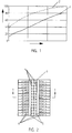
- Figure 2 shows the ceramic burner in accordance with the invention in top view.
- Figure 3 shows a cross-section on line 1-1 in Figure 2.
- The positioning and operation of the burner in the combustion chamber of a hot-blast stove is well known and need not be explained in detail here.
- In Figure 1, the horizontal axis represents the height above the burner and the vertical axis represents the burn-out as a percentage of complete combustion.
Curve 1 represents the burn-out characteristic of the known burner of EP-A-0306072; curve 2 represents that of the illustrated burner in accordance with the invention. Because of the "double" air mixing achieved in the burner of the invention, the maximum burn-out attained is higher (closer to 100%) and a higher burn-out degree is attained at a lower height above the burner. The CO content of the combusted gases which can be achieved with the known burner at a maximum burn-out is of the order of magnitude of 5,000 ppm CO. With the illustrated burner in accordance with the invention this fraction may be reduced to approximately 100 ppm CO. - Figures 2 and 3 show the burner embodying the invention. The burner has a central gas duct 7 which opens at the
central zone 9 of the burner crown.Side air ducts 8 each have a row ofoutlet openings 6, on opposite sides of the central gas duct 7. Within the central gas duct 7 there is acentral air duct 3 which extends vertically upwardly to a top portion where the air flow direction is changed to horizontal, so that the air emerges laterally throughoutlets 4 into the gas flow. This gives the air flow a T-shape path in the central air duct. As seen in Figure 2, the gas comes upwards through the gaps 5. As seen in plan view, from above, theoutlets 4 are positioned between therespective openings 6 along each row of the latter i.e. theopenings 4 and theopenings 6 have staggered relative positions. - In Figure 3 it can be seen that the
side outlets 4 of thecentral air duct 3 are at the height where the gas duct 7 starts to widen upwardly. - Any tendency to inward movement of
partition walls 11 separating theside air ducts 8 from the central gas duct 7 is countered by tongue-and-groove joins 12 on the abutting faces of theelements 10 of the burner crown and the abutting faces of thelowermost elements 10 and the supportingpartition walls 11 andburner body 13. Theburner body 13 and thepartition walls 11 may be cast from a refractory concrete. Thecentral air duct 3 is composed, in this example, of steel sections which have their outer edges bedded in concrete and their inner edges supply the central air flow. For the right-angled overhanging top part, a T-shaped beam may, for example, be fitted on the top of the vertical part of the central air duct. - The
burner crown elements 10 consist of, in this example, three layers laid on top of each other. These elements have been pre-cast in a refractory concrete in moulds. - To operate the burner a combustible gas is supplied to the gas duct 7 and the combustion air needed for combustion is supplied to the
ducts ducts 3 and 90% to 80% in theside ducts 8. Due to the fast and complete mixing the burner makes it possible, to reduce the height of the combustion chamber and to improve the burn-out of the combustion gas. With an air excess of 10% relative to the stoichiometrically required amount of air, the enhanced air mixing can reduce emission of CO by a factor of 50.
Claims (10)
- A ceramic gas burner for a hot blast stove having a burner crown at which gas and air ducts (7,8) have discharge openings, there being a central gas duct (7) and side air ducts (8) which have their discharge openings (6) at both of two opposite sides of the discharge opening of said gas duct (7), characterized by a central air duct (3) which has a discharge opening or openings (4) within said gas duct (7) as seen in plan view.
- A ceramic gas burner according to claim 1 wherein said central air duct (3) has its discharge opening(s) (4) at a central zone of said burner crown.
- A ceramic gas burner according to claim 1 or claim 2 wherein said central air duct (3) extends centrally within said gas duct (7).
- A ceramic gas burner according to any one of claims 1 to 3 wherein said central air duct (3) provides a T-shape flow path for air, in which air flows upwardly along the leg of the T-shape and then laterally along the arms of the T-shape in two opposite directions to discharge openings (4).
- A ceramic gas burner according to any one of claims 1 to 4 wherein said central air duct (3) has a structure comprising an upwardly extending portion and a top portion projecting laterally in an overlapping manner at both of opposite sides of said upwardly extending portion, with said discharge openings (4) located in side faces of said top portion.
- A ceramic gas burner according to any one of claims 1 to 5 wherein said gas duct (7) has an upwardly widening region at said burner crown, and said central air duct (3) has its discharge opening(s) (4) at the height of the lower end of said upwardly widening region.
- A ceramic gas burner according to any one of claims 1 to 6 wherein said side air ducts (8) each have a plurality of discharge openings (6) arranged in respective rows on opposite sides of said gas duct (7), and as seen in plan view said central air duct (3) has a plurality of laterally directed discharge openings (4) at locations which, in the longitudinal direction of said rows, are staggered relative to said discharge openings (6) of said side air ducts (8).
- A ceramic gas burner according to any one of claims 1 to 7 wherein the structure of the burner crown is supported on opposite side walls (13) of the burner which bound said side air ducts (8) and on partition walls (11) which separate said side air ducts (8) from said gas duct (7), and wherein tongue-and-groove constructions are provided in said side walls (13) and said partition walls (11) on the one hand and said burner crown structure on the other hand, so as to locate the burner crown structure horizontally.
- A ceramic gas burner according to any one of claims 1 to 8 wherein said burner is at least partly made of mould-cast concrete.
- A method of operating a ceramic gas burner of a hot blast stove according to any one of claims 1 to 9, wherein of the total air quantity supplied, an amount in the range 10 to 20% by volume is supplied via said central air duct (3) and the remainder via said side air ducts (8).
Applications Claiming Priority (2)
| Application Number | Priority Date | Filing Date | Title |
|---|---|---|---|
| NL9200486 | 1992-03-16 | ||
| NL9200486A NL9200486A (en) | 1992-03-16 | 1992-03-16 | CERAMIC BURNER FOR A FIRE SHAFT FROM A WIND HEATER OF A MAIN OVEN. |
Publications (3)
| Publication Number | Publication Date |
|---|---|
| EP0561449A2 true EP0561449A2 (en) | 1993-09-22 |
| EP0561449A3 EP0561449A3 (en) | 1993-11-18 |
| EP0561449B1 EP0561449B1 (en) | 1995-07-19 |
Family
ID=19860562
Family Applications (1)
| Application Number | Title | Priority Date | Filing Date |
|---|---|---|---|
| EP93200661A Expired - Lifetime EP0561449B1 (en) | 1992-03-16 | 1993-03-08 | Ceramic burner for a hot-blast stove of a blast furnace |
Country Status (16)
| Country | Link |
|---|---|
| US (1) | US5433599A (en) |
| EP (1) | EP0561449B1 (en) |
| CN (1) | CN1029565C (en) |
| AU (1) | AU661893B2 (en) |
| BR (1) | BR9301176A (en) |
| CA (1) | CA2091116C (en) |
| CZ (1) | CZ288746B6 (en) |
| DE (1) | DE69300272T2 (en) |
| ES (1) | ES2074911T3 (en) |
| FI (1) | FI100339B (en) |
| MX (1) | MX9301384A (en) |
| NL (1) | NL9200486A (en) |
| PL (1) | PL170595B1 (en) |
| RU (1) | RU2092739C1 (en) |
| SK (1) | SK19393A3 (en) |
| ZA (1) | ZA931718B (en) |
Cited By (2)
| Publication number | Priority date | Publication date | Assignee | Title |
|---|---|---|---|---|
| DE4409775A1 (en) * | 1994-03-22 | 1995-10-05 | Didier Werke Ag | Burner made from moulded refractory bricks, esp. for waste incinerator |
| CN107152680A (en) * | 2017-05-27 | 2017-09-12 | 鲁西化工集团股份有限公司 | A kind of inertia heat blower burner and circulating wind heater |
Families Citing this family (6)
| Publication number | Priority date | Publication date | Assignee | Title |
|---|---|---|---|---|
| EP1990575A1 (en) * | 2007-05-07 | 2008-11-12 | Paul Wurth Refractory & Engineering GmbH | Ceramic burner |
| NL2003754C2 (en) | 2009-11-04 | 2011-05-10 | Heatteq Refractory Holding B V | Method for improving the combustion efficiency of a burner of a hot blast stove, and such a hot blast stove comprising a gas burner. |
| ES2582863T3 (en) * | 2010-02-12 | 2016-09-15 | Allied Mineral Products, Inc. | Cowper stove and cowper stove dome |
| JP4955117B1 (en) | 2011-03-15 | 2012-06-20 | 新日鉄エンジニアリング株式会社 | Top-fired hot air furnace |
| JP4892107B1 (en) * | 2011-03-23 | 2012-03-07 | 新日鉄エンジニアリング株式会社 | Top-fired hot air furnace |
| CN102537957B (en) * | 2012-01-20 | 2014-11-26 | 何富有 | Novel gas stove head |
Citations (3)
| Publication number | Priority date | Publication date | Assignee | Title |
|---|---|---|---|---|
| DE3240852A1 (en) * | 1982-11-05 | 1984-05-10 | Didier-Werke Ag, 6200 Wiesbaden | Ceramic burner |
| EP0306072A1 (en) * | 1987-08-31 | 1989-03-08 | Hoogovens Groep B.V. | Ceramic gas burner for a combustion chamber of a hot-blast stove |
| US4863378A (en) * | 1987-08-31 | 1989-09-05 | Hoogovens Groep B.V. | Ceramic burner for a hot-blast stove |
Family Cites Families (13)
| Publication number | Priority date | Publication date | Assignee | Title |
|---|---|---|---|---|
| US1754603A (en) * | 1928-05-28 | 1930-04-15 | Charles J Brown | Furnace gas burner |
| US2049150A (en) * | 1932-03-12 | 1936-07-28 | Texas Gulf Sulphur Co | Fuel burner |
| US3044539A (en) * | 1958-12-11 | 1962-07-17 | Eclipse Fuel Eng Co | Process of combustion |
| DE2536073A1 (en) * | 1973-06-15 | 1976-03-25 | O F R Officine Fratelli Riello | Burner head, partic for gaseous fuels - has gas outlet channels sharply divergent from supply pipe axis, and mounted behind plate of the burner |
| US4217088A (en) * | 1977-03-28 | 1980-08-12 | John Zink Company | Burner for very low pressure gases |
| SU723299A1 (en) * | 1978-08-10 | 1980-03-25 | Научно-производственное объединение по технологии машиностроения ЦНИИТМАШ | Burner |
| DE2908427C2 (en) * | 1979-03-05 | 1983-04-14 | L. & C. Steinmüller GmbH, 5270 Gummersbach | Method for reducing NO ↓ X ↓ emissions from the combustion of nitrogenous fuels |
| US4402666A (en) * | 1980-12-09 | 1983-09-06 | John Zink Company | Forced draft radiant wall fuel burner |
| US4642047A (en) * | 1984-08-17 | 1987-02-10 | American Combustion, Inc. | Method and apparatus for flame generation and utilization of the combustion products for heating, melting and refining |
| US4946475A (en) * | 1985-04-16 | 1990-08-07 | The Dow Chemical Company | Apparatus for use with pressurized reactors |
| CN1007920B (en) * | 1985-07-15 | 1990-05-09 | 美国氧化公司 | Method and apparatus for flame generation |
| DE3735002A1 (en) * | 1987-10-16 | 1989-04-27 | Metallgesellschaft Ag | PROCESS FOR REMOVING SULFUR HYDROGEN FROM EXHAUST GAS |
| JP3047996B2 (en) * | 1990-12-18 | 2000-06-05 | 東京電力株式会社 | Coal gasification burner |
-
1992
- 1992-03-16 NL NL9200486A patent/NL9200486A/en not_active Application Discontinuation
-
1993
- 1993-03-05 CA CA002091116A patent/CA2091116C/en not_active Expired - Fee Related
- 1993-03-08 ES ES93200661T patent/ES2074911T3/en not_active Expired - Lifetime
- 1993-03-08 DE DE69300272T patent/DE69300272T2/en not_active Expired - Fee Related
- 1993-03-08 EP EP93200661A patent/EP0561449B1/en not_active Expired - Lifetime
- 1993-03-09 AU AU34063/93A patent/AU661893B2/en not_active Ceased
- 1993-03-10 US US08/028,357 patent/US5433599A/en not_active Expired - Fee Related
- 1993-03-10 CZ CZ1993385A patent/CZ288746B6/en unknown
- 1993-03-10 ZA ZA931718A patent/ZA931718B/en unknown
- 1993-03-11 SK SK19393A patent/SK19393A3/en unknown
- 1993-03-12 MX MX9301384A patent/MX9301384A/en not_active IP Right Cessation
- 1993-03-15 FI FI931141A patent/FI100339B/en active
- 1993-03-15 RU RU9393004770A patent/RU2092739C1/en active
- 1993-03-15 BR BR9301176A patent/BR9301176A/en not_active IP Right Cessation
- 1993-03-16 CN CN93102661A patent/CN1029565C/en not_active Expired - Fee Related
- 1993-03-16 PL PL93298090A patent/PL170595B1/en unknown
Patent Citations (3)
| Publication number | Priority date | Publication date | Assignee | Title |
|---|---|---|---|---|
| DE3240852A1 (en) * | 1982-11-05 | 1984-05-10 | Didier-Werke Ag, 6200 Wiesbaden | Ceramic burner |
| EP0306072A1 (en) * | 1987-08-31 | 1989-03-08 | Hoogovens Groep B.V. | Ceramic gas burner for a combustion chamber of a hot-blast stove |
| US4863378A (en) * | 1987-08-31 | 1989-09-05 | Hoogovens Groep B.V. | Ceramic burner for a hot-blast stove |
Cited By (2)
| Publication number | Priority date | Publication date | Assignee | Title |
|---|---|---|---|---|
| DE4409775A1 (en) * | 1994-03-22 | 1995-10-05 | Didier Werke Ag | Burner made from moulded refractory bricks, esp. for waste incinerator |
| CN107152680A (en) * | 2017-05-27 | 2017-09-12 | 鲁西化工集团股份有限公司 | A kind of inertia heat blower burner and circulating wind heater |
Also Published As
| Publication number | Publication date |
|---|---|
| NL9200486A (en) | 1993-10-18 |
| US5433599A (en) | 1995-07-18 |
| CN1029565C (en) | 1995-08-23 |
| ZA931718B (en) | 1993-09-30 |
| CN1076490A (en) | 1993-09-22 |
| AU3406393A (en) | 1993-09-23 |
| FI100339B (en) | 1997-11-14 |
| FI931141A0 (en) | 1993-03-15 |
| AU661893B2 (en) | 1995-08-10 |
| SK19393A3 (en) | 1993-10-06 |
| EP0561449A3 (en) | 1993-11-18 |
| DE69300272D1 (en) | 1995-08-24 |
| PL170595B1 (en) | 1997-01-31 |
| ES2074911T3 (en) | 1995-09-16 |
| FI931141A (en) | 1993-09-17 |
| CZ288746B6 (en) | 2001-08-15 |
| CA2091116C (en) | 2000-06-06 |
| RU2092739C1 (en) | 1997-10-10 |
| EP0561449B1 (en) | 1995-07-19 |
| PL298090A1 (en) | 1993-10-18 |
| CA2091116A1 (en) | 1993-09-17 |
| BR9301176A (en) | 1993-09-21 |
| CZ38593A3 (en) | 1993-11-17 |
| MX9301384A (en) | 1993-09-01 |
| DE69300272T2 (en) | 1996-01-04 |
Similar Documents
| Publication | Publication Date | Title |
|---|---|---|
| EP0194079B1 (en) | Fluid fuel fired burner | |
| CA1300485C (en) | Gas burners | |
| RU2076292C1 (en) | Ceramic gas burner for hot blast furnace | |
| US5934899A (en) | In-line method of burner firing and NOx emission control for glass melting | |
| US3890084A (en) | Method for reducing burner exhaust emissions | |
| EP0561449B1 (en) | Ceramic burner for a hot-blast stove of a blast furnace | |
| RU2152559C2 (en) | Hydrogen combustion process and burner | |
| CA1315097C (en) | Ceramic gas burner for a combustion chamber of a hot-blast stove | |
| US4511325A (en) | System for the reduction of NOx emissions | |
| US3891384A (en) | Stove burner | |
| EP1046011B1 (en) | Ceramic burner for gases and regenerative heat generator provided with the said burner | |
| US4479778A (en) | Construction of regenerator furnaces | |
| RU2018768C1 (en) | Self-contained injection burner | |
| US3429300A (en) | Industrial furnace burner | |
| US1564049A (en) | Open-hearth furnace | |
| US4416732A (en) | Horizontal coke oven battery | |
| CZ29994A3 (en) | Distribution system for secondary air in a heating equipment | |
| EP1136776B1 (en) | Device for injecting solid fuels in atomised form into a cement kiln | |
| JPH0248408Y2 (en) | ||
| KR870000663B1 (en) | Ceramic burner for gas particularly for a hot-blast stove for a blast furnace | |
| SU1172889A1 (en) | Bath furnace for manufacturing fibre | |
| RU2009395C1 (en) | Furnace | |
| JPH08178544A (en) | Heating furnace | |
| JPH04143508A (en) | Low nox burner | |
| JPH04124512A (en) | Low nox burner |
Legal Events
| Date | Code | Title | Description |
|---|---|---|---|
| PUAI | Public reference made under article 153(3) epc to a published international application that has entered the european phase |
Free format text: ORIGINAL CODE: 0009012 |
|
| AK | Designated contracting states |
Kind code of ref document: A2 Designated state(s): BE DE ES FR GB IT LU SE |
|
| PUAL | Search report despatched |
Free format text: ORIGINAL CODE: 0009013 |
|
| AK | Designated contracting states |
Kind code of ref document: A3 Designated state(s): BE DE ES FR GB IT LU SE |
|
| RIN1 | Information on inventor provided before grant (corrected) |
Inventor name: WESTERVELD, JEAN-PIERRE ANDRE Inventor name: VAN DEN BEMT, JOHANNES CORNELIS ANTOIN Inventor name: BOONACKER, RUDOLF Inventor name: HENDRIKS, AUGUST HUGO Inventor name: VAN LAAR, JACOBUS |
|
| 17P | Request for examination filed |
Effective date: 19930308 |
|
| 17Q | First examination report despatched |
Effective date: 19950110 |
|
| GRAA | (expected) grant |
Free format text: ORIGINAL CODE: 0009210 |
|
| AK | Designated contracting states |
Kind code of ref document: B1 Designated state(s): BE DE ES FR GB IT LU SE |
|
| ITF | It: translation for a ep patent filed | ||
| ET | Fr: translation filed | ||
| REF | Corresponds to: |
Ref document number: 69300272 Country of ref document: DE Date of ref document: 19950824 |
|
| REG | Reference to a national code |
Ref country code: ES Ref legal event code: FG2A Ref document number: 2074911 Country of ref document: ES Kind code of ref document: T3 |
|
| PLBE | No opposition filed within time limit |
Free format text: ORIGINAL CODE: 0009261 |
|
| STAA | Information on the status of an ep patent application or granted ep patent |
Free format text: STATUS: NO OPPOSITION FILED WITHIN TIME LIMIT |
|
| 26N | No opposition filed | ||
| PGFP | Annual fee paid to national office [announced via postgrant information from national office to epo] |
Ref country code: FR Payment date: 20010208 Year of fee payment: 9 |
|
| PGFP | Annual fee paid to national office [announced via postgrant information from national office to epo] |
Ref country code: GB Payment date: 20010219 Year of fee payment: 9 |
|
| PGFP | Annual fee paid to national office [announced via postgrant information from national office to epo] |
Ref country code: DE Payment date: 20010222 Year of fee payment: 9 |
|
| PGFP | Annual fee paid to national office [announced via postgrant information from national office to epo] |
Ref country code: SE Payment date: 20010223 Year of fee payment: 9 |
|
| PGFP | Annual fee paid to national office [announced via postgrant information from national office to epo] |
Ref country code: LU Payment date: 20010306 Year of fee payment: 9 |
|
| PGFP | Annual fee paid to national office [announced via postgrant information from national office to epo] |
Ref country code: ES Payment date: 20010308 Year of fee payment: 9 |
|
| PGFP | Annual fee paid to national office [announced via postgrant information from national office to epo] |
Ref country code: BE Payment date: 20010309 Year of fee payment: 9 |
|
| REG | Reference to a national code |
Ref country code: GB Ref legal event code: IF02 |
|
| PG25 | Lapsed in a contracting state [announced via postgrant information from national office to epo] |
Ref country code: LU Free format text: LAPSE BECAUSE OF NON-PAYMENT OF DUE FEES Effective date: 20020308 Ref country code: GB Free format text: LAPSE BECAUSE OF NON-PAYMENT OF DUE FEES Effective date: 20020308 |
|
| PG25 | Lapsed in a contracting state [announced via postgrant information from national office to epo] |
Ref country code: SE Free format text: LAPSE BECAUSE OF NON-PAYMENT OF DUE FEES Effective date: 20020309 Ref country code: ES Free format text: LAPSE BECAUSE OF NON-PAYMENT OF DUE FEES Effective date: 20020309 |
|
| PG25 | Lapsed in a contracting state [announced via postgrant information from national office to epo] |
Ref country code: BE Free format text: LAPSE BECAUSE OF NON-PAYMENT OF DUE FEES Effective date: 20020331 |
|
| BERE | Be: lapsed |
Owner name: *HOOGOVENS GROEP B.V. Effective date: 20020331 |
|
| PG25 | Lapsed in a contracting state [announced via postgrant information from national office to epo] |
Ref country code: DE Free format text: LAPSE BECAUSE OF NON-PAYMENT OF DUE FEES Effective date: 20021001 |
|
| EUG | Se: european patent has lapsed |
Ref document number: 93200661.2 |
|
| GBPC | Gb: european patent ceased through non-payment of renewal fee |
Effective date: 20020308 |
|
| PG25 | Lapsed in a contracting state [announced via postgrant information from national office to epo] |
Ref country code: FR Free format text: LAPSE BECAUSE OF NON-PAYMENT OF DUE FEES Effective date: 20021129 |
|
| REG | Reference to a national code |
Ref country code: FR Ref legal event code: ST |
|
| REG | Reference to a national code |
Ref country code: ES Ref legal event code: FD2A Effective date: 20030410 |
|
| PG25 | Lapsed in a contracting state [announced via postgrant information from national office to epo] |
Ref country code: IT Free format text: LAPSE BECAUSE OF NON-PAYMENT OF DUE FEES;WARNING: LAPSES OF ITALIAN PATENTS WITH EFFECTIVE DATE BEFORE 2007 MAY HAVE OCCURRED AT ANY TIME BEFORE 2007. THE CORRECT EFFECTIVE DATE MAY BE DIFFERENT FROM THE ONE RECORDED. Effective date: 20050308 |