EP0561282B1 - Brake for road vehicle trailers braked in reverse - Google Patents
Brake for road vehicle trailers braked in reverse Download PDFInfo
- Publication number
- EP0561282B1 EP0561282B1 EP93103969A EP93103969A EP0561282B1 EP 0561282 B1 EP0561282 B1 EP 0561282B1 EP 93103969 A EP93103969 A EP 93103969A EP 93103969 A EP93103969 A EP 93103969A EP 0561282 B1 EP0561282 B1 EP 0561282B1
- Authority
- EP
- European Patent Office
- Prior art keywords
- brake
- lever
- supporting
- brake shoe
- supporting face
- Prior art date
- Legal status (The legal status is an assumption and is not a legal conclusion. Google has not performed a legal analysis and makes no representation as to the accuracy of the status listed.)
- Expired - Lifetime
Links
Images


Classifications
-
- F—MECHANICAL ENGINEERING; LIGHTING; HEATING; WEAPONS; BLASTING
- F16—ENGINEERING ELEMENTS AND UNITS; GENERAL MEASURES FOR PRODUCING AND MAINTAINING EFFECTIVE FUNCTIONING OF MACHINES OR INSTALLATIONS; THERMAL INSULATION IN GENERAL
- F16D—COUPLINGS FOR TRANSMITTING ROTATION; CLUTCHES; BRAKES
- F16D51/00—Brakes with outwardly-movable braking members co-operating with the inner surface of a drum or the like
- F16D51/16—Brakes with outwardly-movable braking members co-operating with the inner surface of a drum or the like shaped as brake-shoes pivoted on a fixed or nearly-fixed axis
- F16D51/18—Brakes with outwardly-movable braking members co-operating with the inner surface of a drum or the like shaped as brake-shoes pivoted on a fixed or nearly-fixed axis with two brake-shoes
- F16D51/20—Brakes with outwardly-movable braking members co-operating with the inner surface of a drum or the like shaped as brake-shoes pivoted on a fixed or nearly-fixed axis with two brake-shoes extending in opposite directions from their pivots
-
- B—PERFORMING OPERATIONS; TRANSPORTING
- B60—VEHICLES IN GENERAL
- B60T—VEHICLE BRAKE CONTROL SYSTEMS OR PARTS THEREOF; BRAKE CONTROL SYSTEMS OR PARTS THEREOF, IN GENERAL; ARRANGEMENT OF BRAKING ELEMENTS ON VEHICLES IN GENERAL; PORTABLE DEVICES FOR PREVENTING UNWANTED MOVEMENT OF VEHICLES; VEHICLE MODIFICATIONS TO FACILITATE COOLING OF BRAKES
- B60T7/00—Brake-action initiating means
- B60T7/12—Brake-action initiating means for automatic initiation; for initiation not subject to will of driver or passenger
- B60T7/20—Brake-action initiating means for automatic initiation; for initiation not subject to will of driver or passenger specially for trailers, e.g. in case of uncoupling of or overrunning by trailer
- B60T7/203—Brake-action initiating means for automatic initiation; for initiation not subject to will of driver or passenger specially for trailers, e.g. in case of uncoupling of or overrunning by trailer with automatic brake release or reduction in case of reverse travel, e.g. by means of mechanisms mounted on the draw bar
- B60T7/206—Brake-action initiating means for automatic initiation; for initiation not subject to will of driver or passenger specially for trailers, e.g. in case of uncoupling of or overrunning by trailer with automatic brake release or reduction in case of reverse travel, e.g. by means of mechanisms mounted on the draw bar by means of mechanisms mounted on trailer drum brakes
Definitions
- the invention relates to a brake and specifically to a drum brake for overrun braked trailers of road vehicles, in particular for car trailers.
- Brakes with automatic reversing are already known which avoid braking or locking of the trailer's wheels when the trailer is reversing, without the need to manually change the braking device.
- the brake or its support device has an auxiliary lever which is pivotably provided at the second end of the primary shoe and by means of which this end is used when braking in forward travel on a stop provided on the anchor plate and which also forms a support for the second end of the secondary brake shoe or for an attachment provided there. Due to the geometry of the lever and the force of the spring biasing this lever into its initial position, care must be taken to ensure that the above-mentioned support of both brake shoes takes place when braking in forward travel.
- a similar brake is known from GB-A-20 94 427.
- the secondary brake shoe acts on the auxiliary lever and pivots it in such a way that the brake shoes release.
- a brake with automatic reversing (FR-A-22 56 059), in which the stop, via which the primary brake shoes are supported on the anchor plate when braking in forward motion, is formed by a lever which is pivotably provided on the anchor plate and which then is pivoted when reversing through the secondary brake shoes against the action of a return spring so that both brake shoes release.
- the disadvantage here is that the total braking forces when driving forward are transmitted via the joint of the auxiliary lever and the geometry of the lever and the force of the return spring are very critical for the functioning of the automatic reversing system.
- the object of the invention is to provide a brake for overrun braked trailers with an automatic reverse system, which is characterized by a particularly simple and robust construction with high operational reliability.
- a brake is designed in accordance with the characterizing part of claim 1.
- the elements of the support device are particularly simple and robust molded parts.
- the support device consists only of the lever and the spacer element, the two brake shoes with their in the initial position of the lever, ie in the state of the support device provided for normal driving (forward driving of the trailer) support the second ends via the lever and the spacer element and thereby activate the actuating device Brake the two brake shoes are pressed against the brake drum in the required manner.
- the first and second support surfaces lie opposite one another on a line which runs tangentially or approximately tangentially to an imaginary circular arc around the axis of the wheel axis.
- the two support surfaces then also have the same or approximately the same radial distance from the axis of the wheel axis.
- the lever When reversing and when the actuating device is actuated, the lever is pivoted out of its initial position in such a way that, by simultaneously pivoting the spacer element, the two second ends of the brake shoes can approach each other and thus, despite the actuating device being activated, there is no braking effect.
- the lever is preferably pivoted in such a way that one of the two support surfaces, preferably the first support surface on the lever, is at a significantly greater radial distance from the axis of the wheel axle than the other support surface.
- 1 is a rigid wheel axle of a trailer which is braked by an overrun brake, for example a car trailer.
- a brake drum 3 is rotatably mounted on both sides of the wheel axle by means of bearing arrangements 2, to which a vehicle wheel or its rim is fastened in a known manner.
- the brake drum 3 is still in a known manner. bell-shaped with a circumferential area 3 ', on the inner surface when braking the two brake shoes 4 and 5 engage with the associated brake pads.
- an essentially circular disk-shaped anchor plate 6 is fastened to the wheel axle 1, in such a way that this anchor plate, which covers the brake drum 3 on the inside, does not rotate with this brake drum.
- the armature plate 6 forms the counter bearing, which absorbs the counter forces that occur during braking.
- the two brake shoes 4 and 5 are each formed partially annular and have a length which corresponds approximately to an angle of 130 ° in the illustrated embodiment respectively.
- the brake shoes 4 and 5 are arranged on the inside of the armature plate 6 facing the interior of the brake drum 3, symmetrically to an imaginary vertical center plane M, which also includes the axis of the brake drum 3 and the wheel axle 1. Between the two ends of the brake shoes 4 and 5 in FIG.
- an expansion lock 7 which forms the actual actuating element of the brake and which interacts with a brake cable, not shown, in such a way that when tensile forces are exerted on the brake cable, this Expanding lock 7 with its two ends, each engaging a brake shoe 4 and 5, generates a spreading force so that the brake shoes 4 and 5 are pressed against the inner surface of the area 3 'of the brake drum 3.
- the expansion lock 7 is arranged in a guide 8 formed on the anchor plate 6, which allows the expansion lock 7 to be displaced by a predetermined amount in an axial direction that is approximately perpendicular to the central plane M or tangential to an imaginary circular arc about the axis of the wheel axis 1 runs.
- arrow A shows the direction of travel of the trailer pulled by a vehicle when driving forward.
- This direction of travel A then gives a direction of rotation B for the wheel in question or the brake drum 3 relative to the wheel axis 1 and the anchor plate 6 fastened there.
- the direction of rotation B runs clockwise, i.e. In this direction of rotation, following the expansion lock 7, the brake shoes 5 are provided, followed by a support device 10 which forms the automatic reversing mechanism and, following this, the brake shoes 4, to which the expansion lock 7 is connected.
- the support device 10 is designed so that it supports the two brake shoes 4 and 5 at their upper ends against each other at a predetermined distance in the direction of rotation B when braking, ie when the expansion lock 7 is activated, and also supports the upper, ie with respect forms on the direction of rotation B front end of the brake shoe 5, so that the spreading force exerted by the expansion lock 7 on the brake shoes 4 and 5 is fully effective as a braking force.
- the support device 10 is further designed so that when driving backwards the team consisting of the trailer and the towing vehicle, in which (driving backwards) a pushing force is exerted on the trailer drawbar and thereby the spreading lock 7 is actuated via the tensioned brake cable, the rotational movement occurring when reversing Brake drum 3 (contrary to arrow B) a cancellation of the mutual support of the upper ends of the brake shoes 4 and 5 and also a cancellation of the support of the brake shoe 5 on the anchor plate 6 in such a way that the brake shoes 4 and 5 none despite the spreading lock 7 Apply braking effect to the brake drum 3, that is, a reversing of the trailer is possible without the manual override of the overrun brake is necessary.
- the support device 10 consists of two plates 11 and 12, of which the plates 11 are fastened in a suitable manner to the anchor plate 6 or to an inwardly drawn region 6 'of this anchor plate.
- the plate 12 is fastened to the plate 11 by means of two screws 13 and 14.
- annular or disc-shaped spacers 15 and 16 are arranged, namely the spacer 15 of the screw 13 and the spacer 16 on the screw 14, so that the two plates 11 and 12th are kept at a predetermined distance.
- the spacer element 15 With its circumferential surface, the spacer element 15 simultaneously forms a support element for a support surface 17 which is curved in the shape of a circular arc and which the brake shoe 15 has at its upper end, which is remote from the expansion lock 7.
- the brake shoe 5 With the support surface 17, the brake shoe 5 lies against the spacer element 15 during normal driving (arrow A) and braking of the trailer and is thus supported on the anchor plate 6, so that the brake shoe 5 also rotates via the expansion lock 7 and the brake shoe also rotates 4 with the brake drum 3 is not possible.
- a lever 18 which is approximately radial to the axis of the wheel axis 1 with its longitudinal extent and forms two concavely curved support surfaces 19 and 20 in its central region, that is to say in the embodiment shown a concave arc .
- These two support surfaces 19 and 20 lie opposite each other in an axial direction that runs approximately perpendicular to the central plane M or tangentially to an imaginary circular arc around the axis of the wheel axis 1.
- the lever 18 With the support surface 19, the lever 18 is supported on its side facing the brake shoe 5 on a shoulder 21 which, with respect to the support surface 17, is formed on the brake shoe 5 so as to be offset radially inward and has a convexly curved end, the shape of which corresponds to the support surface 19 , so that a pivoting of the lever 18 around the free end of the extension 21 is possible by a predetermined amount.
- the one convexly curved end of the rod-shaped spacer element 22 lies against the support surface 20 facing the brake shoe 4, and its other, also convexly curved end rests against a convexly curved support surface 24 at the upper end of the brake shoe 4 is formed.
- a tension spring 24 which is hooked with its other end to the brake shoe 5 and the lever 18 in the sense of pivoting around the neck 21 in the clockwise direction, that is, in the same direction with the direction of rotation B, in such a way that, in the normal state of the support device 10, the radially outer end of the lever 18, with a support surface 25 formed there, bears against the free end of a shoulder 26 which is provided at the upper end of the brake shoe 4, with reference to the axis of the wheel axle 1 offset radially outward with respect to the support surface 23.
- the spacer 22 is in the normal state of the support device 10 with its longitudinal extension in an axial direction which is substantially perpendicular to the central plane M or tangential to an imaginary circular line about the wheel axis, in such a way that the Support surfaces 19 and 20 and 23 are essentially provided on this imaginary circular line.
- the lever 18 and the element 22 are held between the two plates 11 and 12, in such a way that these two elements move in the manner described in more detail below, but are not lost from the space between the two plates 11 and 12 can.
- Another tension spring 27 engages with one end on the upper end of the brake shoe 5 and with the other end on the screw 14. By means of this spring 27, the brake shoe 5 is preloaded in such a way that it rests with its support surface 17 against the spacer element 15.
- the extension 26 acts on the radially outer end of the lever 18, whereby this lever is pivoted counter-clockwise against the action of the spring 24, specifically around the extension 21.
- the above-described pivoting of the lever 18 is supported in that the lever 18 rests with its inner end on a surface facing the brake shoe 4 against a roll pin 28 which is provided on the plate 11, and that when the trailer moves backwards and with the expansion lock 7 actuated initially not only the two brake shoes 4 and 5, but also the lever 18 and the element 22 are carried against the direction of rotation B with the brake drum 3, so that the pivoting of the lever 18 in the counterclockwise direction is at least initiated by the non-carried dowel pin 28.
- the brake shoes 4 and 5 extend with their upper ends into the space formed between the plates 11 and 12.
- the spacer element 16 serves as a contact and guide element, which prevents the upper end of the brake shoe 4 from escaping radially inwards.
- the roll pin 28 has a corresponding function for the upper end of the brake shoe 5.
Landscapes
- Engineering & Computer Science (AREA)
- General Engineering & Computer Science (AREA)
- Mechanical Engineering (AREA)
- Transportation (AREA)
- Braking Arrangements (AREA)
- Regulating Braking Force (AREA)
- Structure Of Transmissions (AREA)
Abstract
Description
Die Erfindung bezieht sich auf eine Bremse und dabei speziell auf eine Trommelbremse für auflaufgebremste Anhänger von Straßenfahrzeugen, insbesondere für PKW-Anhänger gemäß Oberbegriff Patentanspruch 1.The invention relates to a brake and specifically to a drum brake for overrun braked trailers of road vehicles, in particular for car trailers.
Bei auflaufgebremsten Anhängern besteht das Problem, das beim Rückwärtsfahren des von dem Zugfahrzeug und dem Anhänger gebildeten Gespanns durch die auf die Anhängerdeichsel ausgeübte Druckkraft zwangsläufig die Betätigungseinrichtung der Bremse des Anhängers aktiviert wird, so daß die Räder des Anhängers blockieren, sofern nicht besondere Gegenmaßnahmen getroffen werden.In the case of trailers with overrun brakes, there is the problem that when the trailer and trailer formed by the trailer and the trailer force are moved backwards, the actuating device of the trailer brake is inevitably activated, so that the trailer wheels lock unless special countermeasures are taken .
Es sind bereits Bremsen mit Rückfahrautomatik bekannt, die beim Rückwärtsfahren des Gespanns ein Bremsen bzw. Blockieren der Räder des Anhängers vermeiden, und zwar ohne daß ein manuelles Umstellen der Bremseinrichtung erforderlich ist.Brakes with automatic reversing are already known which avoid braking or locking of the trailer's wheels when the trailer is reversing, without the need to manually change the braking device.
Bei einer bekannten Vorrichtung, die die Merkmale des Oberbegriffs des Patentanspruches 1 aufweist (DD-A- 207 817) weist die Bremse bzw. deren Abstützeinrichtung einen an dem zweiten Ende des Primär-Backens schwenkbar vorgesehene Hilfshebel auf, über den sich dieses Ende beim Bremsen in Vorwärtsfahrt an einem an der Ankerplatte vorgesehenen Anschlag abstützt und der zugleich auch eine Abstützung für das zweite Ende des Sekundär-Bremsbackens bzw. für einen dort vorgesehenen Ansatz bildet. Durch die Geometrie des Hebels sowie durch die Kraft der diesen Hebel in seine Ausgangsstellung vorspannenden Feder muß dafür gesorgt werden, daß über den Hebel die genannte Abstützung beider Bremsbacken beim Bremsen in Vorwärtsfahrt erfolgt.In a known device, which has the features of the preamble of claim 1 (DD-A-207 817), the brake or its support device has an auxiliary lever which is pivotably provided at the second end of the primary shoe and by means of which this end is used when braking in forward travel on a stop provided on the anchor plate and which also forms a support for the second end of the secondary brake shoe or for an attachment provided there. Due to the geometry of the lever and the force of the spring biasing this lever into its initial position, care must be taken to ensure that the above-mentioned support of both brake shoes takes place when braking in forward travel.
Eine ähnliche Bremse ist aus der GB-A- 20 94 427 bekannt. Beim Rückwärtsfahren wirkt der Sekundär-Bremsbacken auf den Hilfshebel ein und verschwenkt diesen derart, daß sich die Bremsbacken lösen.A similar brake is known from GB-A-20 94 427. When reversing, the secondary brake shoe acts on the auxiliary lever and pivots it in such a way that the brake shoes release.
Nachteilig ist bei diesen bekannten Bremsen, daß beim Bremsen in Vorwärtsfahrt die gesamte Bremskraft über die gelenkige Verbindung zwischen dem Primär-Bremsbacken und dem Hebel sowie über diesen Hebel auf die Ankerplatte übertragen wird, und daß außerdem die Geometrie des Hebels sowie auch die Kraft der den Hebel in die Ausgangsstellung vorspannenden Feder für die einwandfreie Funktion der Rückfahrautomatik sehr kritisch sind. Eine einwandfreie Arbeitsweise ist nicht in allen Fällen gewährleistet.The disadvantage of these known brakes is that when braking in forward travel, the entire braking force is transmitted to the anchor plate via the articulated connection between the primary brake shoe and the lever and via this lever, and that the geometry of the lever and also the force of the Spring biasing the lever into the initial position are very critical for the proper functioning of the automatic reversing system. Proper functioning is not guaranteed in all cases.
Bekannt ist weiterhin eine Bremse mit Rückfahrautomatik (FR-A- 22 56 059), bei der der Anschlag, über welchen beim Bremsen in Vorwärtsfahrt der Primär-Bremsbacken sich an der Ankerplatte abstützt, von einem an der Ankerplatte schwenkbar vorgesehenen Hebel gebildet ist, der dann beim Rückwärtsfahren durch den Sekundär-Bremsbacken gegen die Wirkung einer Rückstellfeder so verschwenkt wird, daß sich beide Bremsbacken lösen. Nachteilig ist hierbei ist, daß die gesamten Bremskräfte beim Vorwärtsfahren über das Gelenk des Hilfshebels übertragen werden und die Geometrie des Hebels sowie die Kraft der Rückstellfeder für die Funktionsweise der Rückfahrautomatik sehr kritisch sind.Also known is a brake with automatic reversing (FR-A-22 56 059), in which the stop, via which the primary brake shoes are supported on the anchor plate when braking in forward motion, is formed by a lever which is pivotably provided on the anchor plate and which then is pivoted when reversing through the secondary brake shoes against the action of a return spring so that both brake shoes release. The disadvantage here is that the total braking forces when driving forward are transmitted via the joint of the auxiliary lever and the geometry of the lever and the force of the return spring are very critical for the functioning of the automatic reversing system.
Aufgabe der Erfindung ist es, eine Bremse für auflaufgebremste Anhänger mit einer Rückfahrautomatik aufzuzeigen, die sich bei hoher Betriebssicherheit durch eine besonders einfache und robuste Konstruktion auszeichnet.The object of the invention is to provide a brake for overrun braked trailers with an automatic reverse system, which is characterized by a particularly simple and robust construction with high operational reliability.
Zur Lösung dieser Aufgabe ist eine Bremse ensprechend dem kennzeichnenden Teil des Paentanspruches 1 ausgebildet.To solve this problem, a brake is designed in accordance with the characterizing part of claim 1.
Bei der erfindungsgemäßen Bremse sind die Elemente der Abstützeinrichtung besonders einfache und robuste Formteile. Im wesentlichen beseht die Abstützeinrichtung lediglich aus dem Hebel und dem Distanzelement, wobei in der Ausgangsstellung des Hebels, d.h. bei dem für den normalen Fahrbetrieb (Vorwärtsfahren des Anhängers) vorgesehenen Zustand der Abstützeinrichtung sich die beiden Bremsbacken mit ihren zweiten Enden über den Hebel und das Distanzelement abstützen und dadurch beim Aktivieren der Betätigungseinrichtung der Bremse die beiden Bremsbacken in der erforderlichen Weise gegen die Bremstrommel angepreßt werden. In dieser Ausgangsstellung des Hebels liegen sich die erste und zweite Abstützfläche auf einer Linie gegenüber, die tangential oder in etwa tangential zu einem gedachten Kreisbogen um die Achse der Radachse verläuft. Die beiden Abstützflächen besitzen dann von der Achse der Radachse auch den gleichen oder annähernd den gleichen radialen Abstand.In the brake according to the invention, the elements of the support device are particularly simple and robust molded parts. Essentially, the support device consists only of the lever and the spacer element, the two brake shoes with their in the initial position of the lever, ie in the state of the support device provided for normal driving (forward driving of the trailer) support the second ends via the lever and the spacer element and thereby activate the actuating device Brake the two brake shoes are pressed against the brake drum in the required manner. In this initial position of the lever, the first and second support surfaces lie opposite one another on a line which runs tangentially or approximately tangentially to an imaginary circular arc around the axis of the wheel axis. The two support surfaces then also have the same or approximately the same radial distance from the axis of the wheel axis.
Beim Rückwärtsfahren und bei betätigter Betätigungseinrichtung wird der Hebel aus seiner Ausgangsstellung derart verschwenkt, daß durch gleichzeitiges Verschwenken des Distanzelementes sich die beiden zweiten Enden der Bremsbacken einander annähern können und somit trotz aktivierter Betätigungseinrichtung eine Bremswirkung nicht eintritt. Das Schwenken des Hebels erfolgt hierbei bevorzugt so, daß eine der beiden Abstützflächen, vorzugsweise die erste Abstützfläche an dem Hebel einen deutlich größeren radialen Abstand von der Achse der Radachse aufweist als die andere Abstützfläche.When reversing and when the actuating device is actuated, the lever is pivoted out of its initial position in such a way that, by simultaneously pivoting the spacer element, the two second ends of the brake shoes can approach each other and thus, despite the actuating device being activated, there is no braking effect. The lever is preferably pivoted in such a way that one of the two support surfaces, preferably the first support surface on the lever, is at a significantly greater radial distance from the axis of the wheel axle than the other support surface.
Weiterbildungen der Erfindung sind Gegenstand der Unteransprüche.Developments of the invention are the subject of the dependent claims.
Die Erfindung wird im Folgenden anhand der Figuren an einem Ausführungsbeispiel näher erläutert. Es zeigen:
- Fig. 1
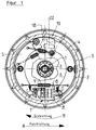
- teilweise im Schnitt eine als Trommelbremse ausgebildete Anhänger-Bremse gemäß der Erfindung;
- Fig. 2
- in vergrößerter Darstellung den die Rückfahrautomatik bildenden Teil der Bremse;
- Fig. 3
- einen Schnitt entsprechend der Linie I-I der Fig. 2.
- Fig. 1
- partly in section a trailer brake designed as a drum brake according to the invention;
- Fig. 2
- in an enlarged view the part of the brake which forms the automatic reversing mechanism;
- Fig. 3
- a section along the line II of FIG. 2nd
In den Figuren ist 1 eine starre Radachse eines auflaufgebremsten Anhängers, beispielsweise PKW-Anhängers. An der Radachsel ist beidseitig mittels Lageranordnungen 2 jeweils eine Bremstrommel 3 drehbar gelagert, an der u.a. in bekannter Weise ein Fahrzeugrad bzw. dessen Felge befestigt ist.In the figures, 1 is a rigid wheel axle of a trailer which is braked by an overrun brake, for example a car trailer. A
Die Bremstrommel 3 ist weiterhin in bekannter Weise napf-bzw. glockenartig mit einem Umfangsbereich 3' ausgebildet, an dessen Innenfläche beim Bremsen die beiden Bremsbacken 4 und 5 mit den zugehörigen Bremsbelägen angreifen.The
An der innenliegenden, d.h. der zur Fahrzeugmitte hin gerichteten Seite ist an der Radachse 1 eine im wesentlichen kreisscheibenförmig ausgebildete Ankerplatte 6 befestigt, und zwar derart, daß diese Ankerplatte, welche die Bremstrommel 3 an der innenliegenden Seite abdeckt, mit dieser Bremstrommel nicht mitdreht. Die Ankerplatte 6 bildet das Gegenlager, welches die beim Bremsen auftretenden Gegenkräfte aufnimmt.On the inside, i.e. the side directed towards the center of the vehicle, an essentially circular disk-
Die beiden Bremsbacken 4 und 5 sind jeweils teilringförmig ausgebildet und besitzen bei der dargestellten Ausführungsform jeweils eine Länge, die etwa einem Winkel von 130o entspricht. Die Bremsbacken 4 und 5 sind an der im Innenraum der Bremstrommel 3 zugewandten Innenseite des Ankerbleches 6 angeordnet, und zwar symmetrisch zu einer gedachten vertikalen Mittelebene M, die auch die Achse der Bremstrommel 3 und der Radachse 1 einschließt. Zwischen den beiden, in der Fig. 1 untenliegenden Enden der Bremsbacken 4 und 5 ist ein Spreizschloß 7 vorgesehen, welches das eigentliche Betätigungselement der Bremse bildet und welches mit einem nicht dargestellten Bremsseil zusammenwirkt, und zwar derart, daß bei auf das Bremsseil ausgeübten Zugkräften das Spreizschloß 7 mit seinen beiden, an jeweils einen Bremsbacken 4 und 5 angreifenden Enden eine spreizende Kraft erzeugt, so daß die Bremsbacken 4 und 5 gegen die Innenfläche des Bereiches 3' der Bremstrommel 3 angedrückt werden. Das Spreizschloß 7 ist in einer an der Ankerplatte 6 ausgebildeten Führung 8 angeordnet, die eine Verschiebung des Spreizschlosses 7 um einen vorgegebenen Betrag in einer Achsrichtung erlaubt, die in etwa senkrecht zur Mittelebene M bzw. tangential zu einem gedachten Kreisbogen um die Achse der Radachse 1 verläuft. Durch eine Zugfeder 9, die mit ihren beiden Enden jeweils an einem Bremsbacken 4 und 5 des unteren, mit dem Spreizschloß 7 zusammenwirkenden Endes eingehängt ist, sind die Bremsbacken 4 und 5 in ihre nichtbremsende Stellung gegen das Spreizschloß 7 vorgespannt.The two
In der Fig. 1 ist mit dem Pfeil A die Fahrtrichtung des von einem Fahrzeug nachgezogenen Anhängers bei Vorwärtsfahrt dargestellt. Aus dieser Fahrtrichtung A ergibt sich dann eine Drehrichtung B für das betreffende Rad bzw. die Bremstrommel 3 relativ zu der Radachse 1 und der dort befestigten Ankerplatte 6. Bei der für die Fig. 1 gewählten Darstellung verläuft die Drehrichtung B im Uhrzeigersinn, d.h. in dieser Drehrichtung ist auf das Spreizschloß 7 folgend der Bremsbacken 5, auf diesen folgend eine die Rückfahrautomatik bildende Abstützeinrichtung 10 und auf diese folgend der Bremsbacken 4 vorgesehen, an welchen sich das Spreizschloß 7 anschließt.In Fig. 1, arrow A shows the direction of travel of the trailer pulled by a vehicle when driving forward. This direction of travel A then gives a direction of rotation B for the wheel in question or the
Die Abstützeinrichtung 10 ist so ausgebildet, daß sie bei der Drehrichtung B beim Bremsen, d.h. bei aktiviertem Spreizschloß 7, die beiden Bremsbacken 4 und 5 an ihren oberen Enden gegeneinander abstützt, auf einem vorgegebenen Abstand hält und außerdem eine Abstützung des oberen, d.h. in bezug auf die Drehrichtung B vorderen Endes des Bremsbackens 5 bildet, so daß die vom Spreizschloß 7 auf die Bremsbacken 4 und 5 ausgeübte Spreizkraft als Bremskraft voll wirksam ist. Die Abstützeinrichtung 10 ist weiterhin so ausgebildet, daß beim Rückwärtsfahren des aus dem Anhänger und dem Zugfahrzeug bestehenden Gespanns, bei dem (Rückwärtsfahren) auf die Anhängerdeichsel eine Schubkraft ausgeübt und dadurch über das gespannte Bremsseil das Spreizschloß 7 betätigt wird, die beim Rückwärtsfahren auftretende Drehbewegung der Bremstrommel 3 (entgegen dem Pfeil B) eine Aufhebung der gegenseitigen Abstützung der oberen Enden der Bremsbacken 4 und 5 sowie auch eine Aufhebung der Abstützung des Bremsbacken 5 an der Ankerplatte 6 in der Weise bewirkt, daß trotz gespreitztem Spreizschloß 7 die Bremsbacken 4 und 5 keine Bremswirkung auf die Bremstrommel 3 ausüben, also ein Rückwärtsfahren des Anhängers möglich ist, ohne daß ein manuelles Umstellen der Auflaufbremse notwendig ist. Eine Besonderheit besteht auch darin, daß die gegenseitige Abstützung der Bremsbacken 4 und 5 an ihren oberen Enden durch die Abstützeinrichtung 10 nur solange wirksam ist, solange tatsächlich das Spreizschloß 7 betätigt ist und über die Bremstrommel 3 auf die gegen diese Bremstrommel anliegenden Bremsbacken 4 und 5 ein Drehmoment entgegen dem Pfeil B um die Achse der Radachse 1 ausgeübt wird.The
Im Detail besteht die Abstützeinrichtung 10 aus zwei Platten 11 und 12, von denen die Platten 11 in geeigneter Weise an dem Ankerblech 6 bzw. an einem nach innen gezogenen Bereich 6' dieses Ankerbleches befestigt ist. Mittels zweier Schrauben 13 und 14 ist die Platte 12 an der Platte 11 befestigt. Auf den Schrauben 13 und 14 sind zwischen den beiden Platten 11 und 12 ring- oder scheibenförmige Distanzelemente 15 bzw. 16 angeordnet, und zwar das Distanzelement 15 der Schraube 13 und das Distanzelement 16 auf der Schraube 14, so daß die beiden Platten 11 und 12 auf einen vorgegebenen Abstand gehalten sind.In detail, the
Das Distanzelement 15 bildet mit seiner Umfangsfläche gleichzeitig ein Abstützelement für eine kreisbogenförmig gekrümmte Abstützfläche 17, die der Bremsbacken 15 an seinem oberen, dem Spreizschloß 7 entfernt liegenden Ende aufweist. Mit der Abstützfläche 17 liegt der Bremsbacken 5 beim normalen Fahren (Pfeil A) und Bremsen des Anhängers gegen das Distanzelement 15 an und stützt sich somit an der Ankerplatte 6 ab, wodurch ein Mitdrehen des Bremsbackens 5 damit über das Spreizschloß 7 auch ein Mitdrehen des Bremsbacken 4 mit der Bremstrommel 3 nicht möglich ist.With its circumferential surface, the
Zwischen den beiden Platten 11 und 12 ist weiterhin ein Hebel 18 angeordnet, der mit seiner Längserstreckung in etwa radial zur Achse der Radachse 1 liegt und in seinem mittleren Bereich zwei jeweils konkav gekrümmte, d.h. bei der dargestellten Ausführungsform kreisbogenförmig konkav gekrümmte Abstützflächen 19 und 20 bildet. Diese beiden Abstützflächen 19 und 20 liegen sich in einer Achsrichtung gegenüber, die in etwa senkrecht zur Mittelebene M bzw. tangential zur einem gedachten Kreisbogen um die Achse der Radachse 1 verläuft.Between the two
Mit der Abstützfläche 19 stützt sich der Hebel 18 an seiner dem Bremsbacken 5 zugewandten Seite an einem Ansatz 21 ab, der bezogen auf die Abstützfläche 17 radial nach innen versetzt am Bremsbacken 5 ausgebildet ist und ein konvex gekrümmtes Ende aufweist, dessen Form der Abstützfläche 19 entspricht, so daß ein Schwenken des Hebels 18 um das freie Ende des Ansatzes 21 um einen vorgegebenen Betrag möglich ist.With the
Gegen die dem Bremsbacken 4 zugewandte Abstützfläche 20 liegt im normalen Zustand der Abstützeinrichtung 10 das eine, konvex gekrümmte Ende des stabförmig ausgebildeten Distanzelementes 22, das mit seinem anderen, ebenfalls konvex gekrümmten Ende gegen eine konvex gekrümmte Abstützfläche 24 anliegt, die am oberen Ende des Bremsbackens 4 gebildet ist.In the normal state of the
An dem radial innenliegenden Ende des Hebels 18 greift eine Zugfeder 24 an, die mit ihrem anderen Ende am Bremsbacken 5 eingehängt ist und den Hebel 18 im Sinne eines Schwenkens um den Ansatz 21 im Uhrzeigersinn, d.h. gleichsinnig mit der Drehrichtung B vorspannt, und zwar derart, daß im normalen Zustand der Abstützeinrichtung 10 das radial außenliegende Ende des Hebels 18 mit einer dort ausgebildeten Abstützfläche 25 gegen das freie Ende eines Ansatzes 26 anliegt, der an dem oberen Ende des Bremsbacken 4 vorgesehen ist, und zwar bezogen auf die Achse der Radachse 1 in bezug auf die Abstützfläche 23 radial nach außen versetzt. Wie die Fig. 1 weiterhin zeigt, liegt das Distanzelement 22 im normalen Zustand der Abstützeinrichtung 10 mit seiner Längserstreckung in einer Achsrichtung, die im wesentlichen senkrecht zur Mittelebene M bzw. tangential zu einer gedachten Kreislinie um die Radachse verläuft, und zwar derart, daß die Abstützflächen 19 und 20 sowie 23 im wesentlichen auf dieser gedachten Kreislinie vorgesehen sind.At the radially inner end of the
Der Hebel 18 sowie das Element 22 sind zwischen den beiden Platten 11 und 12 gehalten, und zwar derart, daß sich diesen beiden Elementen zwar in der nachfolgend noch näher beschriebenen Weise bewegen, aus dem Raum zwischen den beiden Platten 11 und 12 aber nicht verloren gehen können. Eine weitere Zugfeder 27 greift mit einem Ende an dem oberen Ende des Bremsbacken 5 und mit dem anderen Ende an der Schraube 14 an. Durch diese Feder 27 ist der Bremsbacken 5 derart vorgespannt, daß er mit seiner Abstützfläche 17 gegen das Distanzelement 15 anliegt.The
Während des normalen Fahrbetriebes, d.h. während des Vorwärtsfahrens weisen die Elemente die in den Figuren 1 bzw. 2 dargestellte Lage zueinander auf. Beim Bremsen, d.h. bei Betätigung des Spreizschlosses 7 stützen sich die Bremsbacken 4 und 5 über den Ansatz 21, den Hebel 18 und das Element 22 ab. Ein Mitdrehen der Bremsbacken 4 und 5 mit der Bremstrommel 3 ist durch die gegen das Distanzelement 15 anliegende Abstützfläche 17 nicht möglich.During normal driving, i.e. during the forward movement the elements have the position shown in FIGS. When braking, i.e. when the
Wird der Anhänger rückwärts geschoben und hierbei das Spreizschloß 7 betätigt, so wirkt der Ansatz 26 auf das radial außenliegende Ende des Hebels 18 ein, wodurch dieser Hebel gegen die Wirkung der Feder 24 im Gegenuhrzeigersinn geschwenkt wird, und zwar um den Ansatz 21. Hierdurch weicht das an der Abstützfläche 20 anliegende Ende des Elementes 22 radial nach außen aus, und zwar durch Schwenken an der Abstützfläche 23, womit die gegenseitige Abstützung der beiden Bremsbacken 4 und 5 an ihren oberen Enden entfällt und damit auch die Bremswirkung auf die Bremstrommel 3.If the trailer is pushed backwards and the
Das vorbeschriebene Schwenken des Hebels 18 wird dadurch unterstützt, daß der Hebel 18 mit seinem innenliegenden Ende an einer dem Bremsbacken 4 zugewandten Fläche gegen einen Spannstift 28 anliegt, der an der Platte 11 vorgesehen ist, und daß beim Rückwärtsfahren des Anhängers und bei betätigtem Spreizschloß 7 anfänglich nicht nur die beiden Bremsbacken 4 und 5, sondern auch der Hebel 18 und das Element 22 entgegen der Drehrichtung B mit der Bremstrommel 3 mitgeführt werden, so daß durch den nicht mitgeführten Spannstift 28 das Schwenken des Hebels 18 im Gegenuhrzeigersinn zumindest eingeleitet wird.The above-described pivoting of the
Bei der dargestellten Ausführungsform reichen die Bremsbacken 4 und 5 mit ihren oberen Enden in den zwischen den Platten 11 und 12 gebildeten Raum hinein. Hierbei dient das Distanzelement 16 als Anlage- und Führungselement, welches ein seitliches Ausweichen des oberen Endes des Bremsbacken 4 radial nach innen verhindert. Eine entsprechende Funktion hat der Spannstift 28 für das obere Ende des Bremsbacken 5.In the illustrated embodiment, the
Die Erfindung wurde voranstehend an einem Ausführungsbeispiel beschrieben. Es versteht sich, daß Änderungen sowie Abwandlungen möglich sind, ohne daß dadurch die Erfindung im Rahmen der anliegenden Patentansprüche verlassen wird.The invention has been described above using an exemplary embodiment. It goes without saying that changes and modifications are possible without thereby leaving the invention within the scope of the appended claims.
- 11
- RadachseWheel axle
- 22nd
- LageranordnungBearing arrangement
- 33rd
- BremstrommelBrake drum
- 3'3 '
- UmfangsbereichCircumferential area
- 4, 54, 5
- BremsbackenBrake shoes
- 66
- AnkerplatteAnchor plate
- 77
- SpreizschloßExpansion lock
- 88th
- Führungguide
- 99
- Federfeather
- 1010th
- AbstützeinrichtungSupport device
- 11, 1211, 12
- Platteplate
- 13, 1413, 14
- Schraubescrew
- 15, 1615, 16
- DistanzelementSpacer
- 1717th
- AbstützflächeSupport surface
- 1818th
- Hebellever
- 19, 2019, 20
- AbstützflächeSupport surface
- 2121
- Ansatzapproach
- 2222
- DistanzelementSpacer
- 2323
- AbstützflächeSupport surface
- 2424th
- Federfeather
- 2525th
- AbstützflächeSupport surface
- 2626
- Ansatzapproach
- 2727
- ZugfederTension spring
- 2828
- SpannstiftSpring pin
Claims (10)
- Brake for an overrun-braked1 trailer for road vehicles, in particular a car trailer, with a brake drum (3) rotatably mounted on a wheel axle (1), with an anchor plate (6) fastened to the wheel axle in a torsion-proof manner, with two brake shoes (4, 5) which are provided on the anchor plate (6) so as to be movable, by a predetermined angle of rotation, about the axis of the wheel axle (1), with an actuating arrangement (7) which acts on a first end, in each case, of each brake shoe (4, 5) and, in the activated condition, spreads the brake shoes (4, 5) apart, and also with a supporting arrangement (10), which is constructed as an automatic reversing system, on the second ends of the brake shoes (4, 5), while the supporting arrangement (10) forms a supporting element (15), which is provided on the anchor plate (6), for the second end of the primary brake shoe (5) which precedes the secondary brake shoe (4), in the region of the supporting arrangement (10), in a first rotational direction (B) of the brake drum (3) that corresponds to the forward travel of the trailer, while the supporting arrangement (10) possesses a lever (18) which forms a first supporting face (20) and is mounted, at the second end of the primary brake shoe (5), so as to be rotatable about an axis parallel to the wheel axle, and against which (lever (18)) an extension (26) on the second end of the secondary brake shoe (4) abuts, while the lever (18) can be tilted on the supporting arrangement (10) out of a starting position, when the trailer travels backwards and when the actuating arrangement (7) is activated, for the purpose of releasing the brake shoes (4, 5),
characterised in that a second supporting face (23) is formed, opposite the first supporting face, at the second end of the secondary brake shoe (4), and that a distance element (22) disposed between the lever (18) and the second end of the secondary brake shoe (4) is supported, by two ends, on the first supporting face (20) on the lever (18) and on the second supporting face (23) on the second end of the secondary brake shoe (4). - Brake according to claim 1, characterised in that the first supporting face (20) has the same, or approximately the same, radial distance from the axis of the wheel axle (1) as the articulating connection between the lever (18) and the primary brake shoe (5).
- Brake according to claim 1 or 2, characterised in that the second supporting face (23) has a radial distance from the axis of the wheel axle (1) which is equal, or approximately equal, to the distance of the first supporting face (20) from the said axis.
- Brake according to one of claims 1 to 3, characterised in that the lever (28) forms, on a side which faces away from the first supporting face (20), a third supporting face (19) by which the lever (18) abuts in a pivoting manner against a counterface, which is preferably formed by an extension (21), on the second end of the primary brake shoe (5).
- Brake according to one of claims 1 to 4, characterised in that the supporting faces (19, 20, 23) are concavely curved, preferably concavely curved in the shape of a circular arc, and that the ends, which interact with the said supporting faces (19, 20, 23), of the distance element (22) or the counterface of the primary brake shoe (5) are designed so as to be convexly curved, preferably convexly curved in the shape of a circular arc.
- Brake according to one of claims 1 to 5, characterised in that the distance element (22) is an elongated or bar-shaped element.
- Brake according to one of claims 1 to 6, characterised in that, when the lever (18) is pivoted radially to the axis of the wheel axle (1), out of its starting position, the distance element is tilted, and preferably pivoted forwards and outwards, by its end that abuts against the first supporting face (20).
- Brake according to one of claims 1 to 7, characterised in that the extension at the second end of the secondary brake shoe (4) acts upon the lever (18) in a manner which is offset radially to the first supporting face (20), in fact is preferably offset radially outwards in relation to the first supporting face (20).
- Brake according to one of claims 1 to 8, characterised by a spring (24) that pre-tensions the lever (18) into its starting position.
- Brake according to one of claims 1 to 9, characterised by a stop, which is formed, for example, by a clamping pin (28) and provided on the anchor plate (8) and against which the lever (18) abuts in the starting position.
Applications Claiming Priority (2)
| Application Number | Priority Date | Filing Date | Title |
|---|---|---|---|
| DE4208424A DE4208424C2 (en) | 1992-03-17 | 1992-03-17 | Brake for overrun braked trailers for road vehicles |
| DE4208424 | 1992-03-17 |
Publications (3)
| Publication Number | Publication Date |
|---|---|
| EP0561282A2 EP0561282A2 (en) | 1993-09-22 |
| EP0561282A3 EP0561282A3 (en) | 1994-03-02 |
| EP0561282B1 true EP0561282B1 (en) | 1996-12-18 |
Family
ID=6454219
Family Applications (1)
| Application Number | Title | Priority Date | Filing Date |
|---|---|---|---|
| EP93103969A Expired - Lifetime EP0561282B1 (en) | 1992-03-17 | 1993-03-11 | Brake for road vehicle trailers braked in reverse |
Country Status (3)
| Country | Link |
|---|---|
| EP (1) | EP0561282B1 (en) |
| AT (1) | ATE146415T1 (en) |
| DE (2) | DE4208424C2 (en) |
Families Citing this family (1)
| Publication number | Priority date | Publication date | Assignee | Title |
|---|---|---|---|---|
| EP0629534A3 (en) * | 1993-06-16 | 1995-03-15 | Gerhard Spaegele | Mechanical release device. |
Family Cites Families (5)
| Publication number | Priority date | Publication date | Assignee | Title |
|---|---|---|---|---|
| DE2364822C3 (en) * | 1973-12-28 | 1983-04-07 | Hahn Fahrzeugbau Gmbh, 7012 Fellbach | Inner shoe brake for an overrun brake device for trailers |
| EP0013674B1 (en) * | 1979-01-29 | 1982-10-27 | Leslie Cyril Chouings | Shoe and drum brake |
| DD207817A3 (en) * | 1981-09-22 | 1984-03-14 | Friedbert Rockstroh | DISTANCE DEVICE FOR INTERIOR BRAKES WITH BACK-UP MACHINERY FOR LARGEST MOUNTED TRAILERS |
| DD158488A3 (en) * | 1981-03-11 | 1983-01-19 | Helmfried Dunse | COUNTERPIECE ARRANGEMENT FOR INTERIOR BRAKING BRAKES OF LARGEST MOUNTED TRAILERS |
| FR2636904B1 (en) * | 1988-09-27 | 1994-04-08 | Thibault Essieux Rtn | INERTIA BRAKING DEVICE FOR TRAILER WITH AUTOMATIC RELEASE OF REVERSE BRAKING |
-
1992
- 1992-03-17 DE DE4208424A patent/DE4208424C2/en not_active Expired - Fee Related
-
1993
- 1993-03-11 EP EP93103969A patent/EP0561282B1/en not_active Expired - Lifetime
- 1993-03-11 AT AT93103969T patent/ATE146415T1/en not_active IP Right Cessation
- 1993-03-11 DE DE59304774T patent/DE59304774D1/en not_active Expired - Fee Related
Also Published As
| Publication number | Publication date |
|---|---|
| ATE146415T1 (en) | 1997-01-15 |
| DE4208424A1 (en) | 1993-09-23 |
| EP0561282A3 (en) | 1994-03-02 |
| EP0561282A2 (en) | 1993-09-22 |
| DE59304774D1 (en) | 1997-01-30 |
| DE4208424C2 (en) | 2000-12-21 |
Similar Documents
| Publication | Publication Date | Title |
|---|---|---|
| EP2682635B1 (en) | Brake actuator mechanism for a disc brake | |
| EP0662403B1 (en) | Seat adjustment | |
| DE2344691C3 (en) | Mechanical release device for a spring brake cylinder, in particular for rail vehicle compressed air brake systems | |
| DE19854945A1 (en) | Pinch roller switch mechanism | |
| EP0413197A1 (en) | Castor for platforms, scaffoldings or similar | |
| DE2508375A1 (en) | PARKING BRAKE FOR VEHICLES | |
| EP0261660B1 (en) | Wheel brake for trailer | |
| EP0561282B1 (en) | Brake for road vehicle trailers braked in reverse | |
| DE2116175C2 (en) | Adjustment device for a vehicle brake | |
| EP1451025B1 (en) | Wheel bearing on an axle body for vehicles | |
| DE3033582C2 (en) | ||
| EP2334524B1 (en) | Pneumatic brake device | |
| DE202017103040U1 (en) | Carrier assembly for a vehicle | |
| EP0208151B1 (en) | Chassis for trailers with an overrun brake | |
| DE2114659C3 (en) | Inner shoe brake for vehicles in which the application member is floating in the brake carrier | |
| DE2640304A1 (en) | Mechanically operated vehicle disc brake - has axially spreadable disc pair turned in opposite directions by lever and link mechanism | |
| DE2932340C2 (en) | ||
| DE2519917C3 (en) | Hand brake valve for trucks with trailers | |
| DE3504040A1 (en) | BRAKE GAME CONTROL FOR RAILWAY CARS | |
| DE69630582T2 (en) | Ergonomic handwheel for a railway vehicle handbrake | |
| DE2106664A1 (en) | Overrun braking system for trailers | |
| DE1530500C3 (en) | Disc brake | |
| DE4024455C2 (en) | Automatic adjustment device for simplex and duo-duplex brakes | |
| DE3132581A1 (en) | "SPRING-LOCK BRAKE CYLINDER" | |
| DE3228796A1 (en) | Automatic adjustment device for the brake lever of a brake |
Legal Events
| Date | Code | Title | Description |
|---|---|---|---|
| PUAI | Public reference made under article 153(3) epc to a published international application that has entered the european phase |
Free format text: ORIGINAL CODE: 0009012 |
|
| AK | Designated contracting states |
Kind code of ref document: A2 Designated state(s): AT DE ES FR GB IT NL PT |
|
| PUAL | Search report despatched |
Free format text: ORIGINAL CODE: 0009013 |
|
| AK | Designated contracting states |
Kind code of ref document: A3 Designated state(s): AT DE ES FR GB IT NL PT |
|
| 17P | Request for examination filed |
Effective date: 19940622 |
|
| 17Q | First examination report despatched |
Effective date: 19950111 |
|
| GRAG | Despatch of communication of intention to grant |
Free format text: ORIGINAL CODE: EPIDOS AGRA |
|
| GRAH | Despatch of communication of intention to grant a patent |
Free format text: ORIGINAL CODE: EPIDOS IGRA |
|
| GRAH | Despatch of communication of intention to grant a patent |
Free format text: ORIGINAL CODE: EPIDOS IGRA |
|
| GRAA | (expected) grant |
Free format text: ORIGINAL CODE: 0009210 |
|
| AK | Designated contracting states |
Kind code of ref document: B1 Designated state(s): AT DE ES FR GB IT NL PT |
|
| PG25 | Lapsed in a contracting state [announced via postgrant information from national office to epo] |
Ref country code: NL Free format text: LAPSE BECAUSE OF FAILURE TO SUBMIT A TRANSLATION OF THE DESCRIPTION OR TO PAY THE FEE WITHIN THE PRESCRIBED TIME-LIMIT Effective date: 19961218 Ref country code: IT Free format text: LAPSE BECAUSE OF FAILURE TO SUBMIT A TRANSLATION OF THE DESCRIPTION OR TO PAY THE FEE WITHIN THE PRE;WARNING: LAPSES OF ITALIAN PATENTS WITH EFFECTIVE DATE BEFORE 2007 MAY HAVE OCCURRED AT ANY TIME BEFORE 2007. THE CORRECT EFFECTIVE DATE MAY BE DIFFERENT FROM THE ONE RECORDED.SCRIBED TIME-LIMIT Effective date: 19961218 Ref country code: GB Effective date: 19961218 Ref country code: FR Effective date: 19961218 Ref country code: ES Free format text: THE PATENT HAS BEEN ANNULLED BY A DECISION OF A NATIONAL AUTHORITY Effective date: 19961218 |
|
| REF | Corresponds to: |
Ref document number: 146415 Country of ref document: AT Date of ref document: 19970115 Kind code of ref document: T |
|
| REF | Corresponds to: |
Ref document number: 59304774 Country of ref document: DE Date of ref document: 19970130 |
|
| PG25 | Lapsed in a contracting state [announced via postgrant information from national office to epo] |
Ref country code: AT Free format text: LAPSE BECAUSE OF NON-PAYMENT OF DUE FEES Effective date: 19970311 |
|
| PG25 | Lapsed in a contracting state [announced via postgrant information from national office to epo] |
Ref country code: PT Effective date: 19970318 |
|
| EN | Fr: translation not filed | ||
| NLV1 | Nl: lapsed or annulled due to failure to fulfill the requirements of art. 29p and 29m of the patents act | ||
| GBV | Gb: ep patent (uk) treated as always having been void in accordance with gb section 77(7)/1977 [no translation filed] |
Effective date: 19961218 |
|
| PLBE | No opposition filed within time limit |
Free format text: ORIGINAL CODE: 0009261 |
|
| STAA | Information on the status of an ep patent application or granted ep patent |
Free format text: STATUS: NO OPPOSITION FILED WITHIN TIME LIMIT |
|
| 26N | No opposition filed | ||
| PGFP | Annual fee paid to national office [announced via postgrant information from national office to epo] |
Ref country code: DE Payment date: 20000522 Year of fee payment: 8 |
|
| PG25 | Lapsed in a contracting state [announced via postgrant information from national office to epo] |
Ref country code: DE Free format text: LAPSE BECAUSE OF NON-PAYMENT OF DUE FEES Effective date: 20020101 |