EP0560980B1 - Membrane bioreactor system for treating synthetic metal-working fluids and oil-based products - Google Patents
Membrane bioreactor system for treating synthetic metal-working fluids and oil-based products Download PDFInfo
- Publication number
- EP0560980B1 EP0560980B1 EP19930906356 EP93906356A EP0560980B1 EP 0560980 B1 EP0560980 B1 EP 0560980B1 EP 19930906356 EP19930906356 EP 19930906356 EP 93906356 A EP93906356 A EP 93906356A EP 0560980 B1 EP0560980 B1 EP 0560980B1
- Authority
- EP
- European Patent Office
- Prior art keywords
- solids
- wastewater
- membrane
- permeate
- zone
- Prior art date
- Legal status (The legal status is an assumption and is not a legal conclusion. Google has not performed a legal analysis and makes no representation as to the accuracy of the status listed.)
- Expired - Lifetime
Links
- 239000012528 membrane Substances 0.000 title claims abstract description 80
- 239000012530 fluid Substances 0.000 title claims abstract description 31
- 238000005555 metalworking Methods 0.000 title claims abstract description 14
- 239000007787 solid Substances 0.000 claims abstract description 63
- 239000002351 wastewater Substances 0.000 claims abstract description 49
- 239000012466 permeate Substances 0.000 claims abstract description 36
- 239000002699 waste material Substances 0.000 claims abstract description 29
- 230000004907 flux Effects 0.000 claims abstract description 27
- 239000012141 concentrate Substances 0.000 claims abstract description 20
- 239000003921 oil Substances 0.000 claims abstract description 19
- 230000014759 maintenance of location Effects 0.000 claims abstract description 13
- 238000001914 filtration Methods 0.000 claims abstract description 12
- 244000005700 microbiome Species 0.000 claims abstract description 10
- 239000003925 fat Substances 0.000 claims abstract description 6
- 239000000203 mixture Substances 0.000 claims abstract description 6
- XLYOFNOQVPJJNP-UHFFFAOYSA-N water Substances O XLYOFNOQVPJJNP-UHFFFAOYSA-N 0.000 claims abstract description 5
- 238000000034 method Methods 0.000 claims description 33
- 230000008569 process Effects 0.000 claims description 33
- 239000002028 Biomass Substances 0.000 claims description 14
- QVGXLLKOCUKJST-UHFFFAOYSA-N atomic oxygen Chemical compound [O] QVGXLLKOCUKJST-UHFFFAOYSA-N 0.000 claims description 8
- 239000007788 liquid Substances 0.000 claims description 8
- 229910052760 oxygen Inorganic materials 0.000 claims description 8
- 239000001301 oxygen Substances 0.000 claims description 8
- 239000000126 substance Substances 0.000 claims description 8
- 239000007900 aqueous suspension Substances 0.000 claims description 6
- 238000005374 membrane filtration Methods 0.000 claims description 5
- 238000006243 chemical reaction Methods 0.000 claims description 3
- 150000002902 organometallic compounds Chemical class 0.000 claims description 3
- 239000003208 petroleum Substances 0.000 claims description 3
- 238000004065 wastewater treatment Methods 0.000 claims description 2
- 239000000725 suspension Substances 0.000 claims 5
- 230000000266 injurious effect Effects 0.000 claims 2
- 238000003754 machining Methods 0.000 claims 2
- 230000001580 bacterial effect Effects 0.000 claims 1
- 238000010924 continuous production Methods 0.000 claims 1
- 230000000717 retained effect Effects 0.000 claims 1
- 238000000108 ultra-filtration Methods 0.000 abstract description 10
- 238000004519 manufacturing process Methods 0.000 abstract description 5
- 239000000463 material Substances 0.000 abstract description 5
- 238000012360 testing method Methods 0.000 abstract description 4
- 239000002245 particle Substances 0.000 abstract description 2
- 239000010865 sewage Substances 0.000 abstract description 2
- HBMJWWWQQXIZIP-UHFFFAOYSA-N silicon carbide Chemical compound [Si+]#[C-] HBMJWWWQQXIZIP-UHFFFAOYSA-N 0.000 abstract description 2
- 229910010271 silicon carbide Inorganic materials 0.000 abstract description 2
- 239000002184 metal Substances 0.000 abstract 1
- 230000002035 prolonged effect Effects 0.000 abstract 1
- 235000015097 nutrients Nutrition 0.000 description 8
- IJGRMHOSHXDMSA-UHFFFAOYSA-N Atomic nitrogen Chemical compound N#N IJGRMHOSHXDMSA-UHFFFAOYSA-N 0.000 description 6
- 238000009825 accumulation Methods 0.000 description 5
- 150000001875 compounds Chemical class 0.000 description 4
- 239000004215 Carbon black (E152) Substances 0.000 description 3
- 239000000470 constituent Substances 0.000 description 3
- 230000000694 effects Effects 0.000 description 3
- 229930195733 hydrocarbon Natural products 0.000 description 3
- 150000002430 hydrocarbons Chemical class 0.000 description 3
- 230000000813 microbial effect Effects 0.000 description 3
- 229910052757 nitrogen Inorganic materials 0.000 description 3
- 239000010815 organic waste Substances 0.000 description 3
- 239000011148 porous material Substances 0.000 description 3
- 239000000047 product Substances 0.000 description 3
- 238000004064 recycling Methods 0.000 description 3
- QGZKDVFQNNGYKY-UHFFFAOYSA-N Ammonia Chemical compound N QGZKDVFQNNGYKY-UHFFFAOYSA-N 0.000 description 2
- 241000894006 Bacteria Species 0.000 description 2
- 229910019142 PO4 Inorganic materials 0.000 description 2
- OAICVXFJPJFONN-UHFFFAOYSA-N Phosphorus Chemical compound [P] OAICVXFJPJFONN-UHFFFAOYSA-N 0.000 description 2
- QAOWNCQODCNURD-UHFFFAOYSA-N Sulfuric acid Chemical compound OS(O)(=O)=O QAOWNCQODCNURD-UHFFFAOYSA-N 0.000 description 2
- 230000009471 action Effects 0.000 description 2
- 239000003513 alkali Substances 0.000 description 2
- 238000004458 analytical method Methods 0.000 description 2
- 238000006065 biodegradation reaction Methods 0.000 description 2
- 230000015556 catabolic process Effects 0.000 description 2
- 239000007795 chemical reaction product Substances 0.000 description 2
- 238000004140 cleaning Methods 0.000 description 2
- 238000006731 degradation reaction Methods 0.000 description 2
- 238000005516 engineering process Methods 0.000 description 2
- 238000002657 hormone replacement therapy Methods 0.000 description 2
- 238000001471 micro-filtration Methods 0.000 description 2
- NBIIXXVUZAFLBC-UHFFFAOYSA-K phosphate Chemical compound [O-]P([O-])([O-])=O NBIIXXVUZAFLBC-UHFFFAOYSA-K 0.000 description 2
- 239000010452 phosphate Substances 0.000 description 2
- 229910052698 phosphorus Inorganic materials 0.000 description 2
- 239000011574 phosphorus Substances 0.000 description 2
- 230000010287 polarization Effects 0.000 description 2
- -1 poly(vinyl alcohol) Polymers 0.000 description 2
- 230000009467 reduction Effects 0.000 description 2
- 230000035945 sensitivity Effects 0.000 description 2
- 239000010802 sludge Substances 0.000 description 2
- 239000000758 substrate Substances 0.000 description 2
- 241000590020 Achromobacter Species 0.000 description 1
- 241000604933 Bdellovibrio Species 0.000 description 1
- 241000233866 Fungi Species 0.000 description 1
- 241001149900 Fusconaia subrotunda Species 0.000 description 1
- 241000605159 Nitrobacter Species 0.000 description 1
- 241000187654 Nocardia Species 0.000 description 1
- 239000004677 Nylon Substances 0.000 description 1
- 239000004743 Polypropylene Substances 0.000 description 1
- ZLMJMSJWJFRBEC-UHFFFAOYSA-N Potassium Chemical compound [K] ZLMJMSJWJFRBEC-UHFFFAOYSA-N 0.000 description 1
- 241000589516 Pseudomonas Species 0.000 description 1
- 101000916532 Rattus norvegicus Zinc finger and BTB domain-containing protein 38 Proteins 0.000 description 1
- 240000004808 Saccharomyces cerevisiae Species 0.000 description 1
- 239000002253 acid Substances 0.000 description 1
- 230000002411 adverse Effects 0.000 description 1
- 229910021529 ammonia Inorganic materials 0.000 description 1
- 239000010828 animal waste Substances 0.000 description 1
- 230000003466 anti-cipated effect Effects 0.000 description 1
- 230000001651 autotrophic effect Effects 0.000 description 1
- 238000011021 bench scale process Methods 0.000 description 1
- 238000002425 crystallisation Methods 0.000 description 1
- 230000008025 crystallization Effects 0.000 description 1
- 230000008021 deposition Effects 0.000 description 1
- 238000013461 design Methods 0.000 description 1
- 230000006866 deterioration Effects 0.000 description 1
- 239000003344 environmental pollutant Substances 0.000 description 1
- 238000002474 experimental method Methods 0.000 description 1
- 230000005484 gravity Effects 0.000 description 1
- 239000004519 grease Substances 0.000 description 1
- 239000010800 human waste Substances 0.000 description 1
- 238000006460 hydrolysis reaction Methods 0.000 description 1
- 230000002401 inhibitory effect Effects 0.000 description 1
- 230000005764 inhibitory process Effects 0.000 description 1
- 229910003480 inorganic solid Inorganic materials 0.000 description 1
- 239000002207 metabolite Substances 0.000 description 1
- 239000002923 metal particle Substances 0.000 description 1
- 238000002156 mixing Methods 0.000 description 1
- 239000010841 municipal wastewater Substances 0.000 description 1
- 230000007935 neutral effect Effects 0.000 description 1
- QJGQUHMNIGDVPM-UHFFFAOYSA-N nitrogen group Chemical group [N] QJGQUHMNIGDVPM-UHFFFAOYSA-N 0.000 description 1
- 229920001778 nylon Polymers 0.000 description 1
- 150000002894 organic compounds Chemical class 0.000 description 1
- 230000000704 physical effect Effects 0.000 description 1
- 231100000719 pollutant Toxicity 0.000 description 1
- 229920002492 poly(sulfone) Polymers 0.000 description 1
- 229920001155 polypropylene Polymers 0.000 description 1
- 229920002451 polyvinyl alcohol Polymers 0.000 description 1
- 229910052700 potassium Inorganic materials 0.000 description 1
- 239000011591 potassium Substances 0.000 description 1
- 238000001556 precipitation Methods 0.000 description 1
- 238000010926 purge Methods 0.000 description 1
- 238000005070 sampling Methods 0.000 description 1
- 239000002904 solvent Substances 0.000 description 1
- 238000001228 spectrum Methods 0.000 description 1
- 238000011105 stabilization Methods 0.000 description 1
- 239000013589 supplement Substances 0.000 description 1
- 238000012546 transfer Methods 0.000 description 1
Images

Classifications
-
- C—CHEMISTRY; METALLURGY
- C02—TREATMENT OF WATER, WASTE WATER, SEWAGE, OR SLUDGE
- C02F—TREATMENT OF WATER, WASTE WATER, SEWAGE, OR SLUDGE
- C02F3/00—Biological treatment of water, waste water, or sewage
- C02F3/02—Aerobic processes
- C02F3/12—Activated sludge processes
- C02F3/1236—Particular type of activated sludge installations
- C02F3/1268—Membrane bioreactor systems
-
- C—CHEMISTRY; METALLURGY
- C02—TREATMENT OF WATER, WASTE WATER, SEWAGE, OR SLUDGE
- C02F—TREATMENT OF WATER, WASTE WATER, SEWAGE, OR SLUDGE
- C02F1/00—Treatment of water, waste water, or sewage
- C02F1/44—Treatment of water, waste water, or sewage by dialysis, osmosis or reverse osmosis
-
- B—PERFORMING OPERATIONS; TRANSPORTING
- B01—PHYSICAL OR CHEMICAL PROCESSES OR APPARATUS IN GENERAL
- B01D—SEPARATION
- B01D17/00—Separation of liquids, not provided for elsewhere, e.g. by thermal diffusion
-
- B—PERFORMING OPERATIONS; TRANSPORTING
- B01—PHYSICAL OR CHEMICAL PROCESSES OR APPARATUS IN GENERAL
- B01D—SEPARATION
- B01D17/00—Separation of liquids, not provided for elsewhere, e.g. by thermal diffusion
- B01D17/02—Separation of non-miscible liquids
- B01D17/0208—Separation of non-miscible liquids by sedimentation
-
- B—PERFORMING OPERATIONS; TRANSPORTING
- B01—PHYSICAL OR CHEMICAL PROCESSES OR APPARATUS IN GENERAL
- B01D—SEPARATION
- B01D17/00—Separation of liquids, not provided for elsewhere, e.g. by thermal diffusion
- B01D17/02—Separation of non-miscible liquids
- B01D17/0208—Separation of non-miscible liquids by sedimentation
- B01D17/0214—Separation of non-miscible liquids by sedimentation with removal of one of the phases
-
- B—PERFORMING OPERATIONS; TRANSPORTING
- B01—PHYSICAL OR CHEMICAL PROCESSES OR APPARATUS IN GENERAL
- B01D—SEPARATION
- B01D17/00—Separation of liquids, not provided for elsewhere, e.g. by thermal diffusion
- B01D17/02—Separation of non-miscible liquids
- B01D17/04—Breaking emulsions
- B01D17/047—Breaking emulsions with separation aids
-
- B—PERFORMING OPERATIONS; TRANSPORTING
- B01—PHYSICAL OR CHEMICAL PROCESSES OR APPARATUS IN GENERAL
- B01D—SEPARATION
- B01D17/00—Separation of liquids, not provided for elsewhere, e.g. by thermal diffusion
- B01D17/08—Thickening liquid suspensions by filtration
- B01D17/085—Thickening liquid suspensions by filtration with membranes
-
- B—PERFORMING OPERATIONS; TRANSPORTING
- B01—PHYSICAL OR CHEMICAL PROCESSES OR APPARATUS IN GENERAL
- B01D—SEPARATION
- B01D21/00—Separation of suspended solid particles from liquids by sedimentation
-
- B—PERFORMING OPERATIONS; TRANSPORTING
- B01—PHYSICAL OR CHEMICAL PROCESSES OR APPARATUS IN GENERAL
- B01D—SEPARATION
- B01D21/00—Separation of suspended solid particles from liquids by sedimentation
- B01D21/24—Feed or discharge mechanisms for settling tanks
- B01D21/2433—Discharge mechanisms for floating particles
-
- B—PERFORMING OPERATIONS; TRANSPORTING
- B01—PHYSICAL OR CHEMICAL PROCESSES OR APPARATUS IN GENERAL
- B01D—SEPARATION
- B01D21/00—Separation of suspended solid particles from liquids by sedimentation
- B01D21/24—Feed or discharge mechanisms for settling tanks
- B01D21/2444—Discharge mechanisms for the classified liquid
-
- B—PERFORMING OPERATIONS; TRANSPORTING
- B01—PHYSICAL OR CHEMICAL PROCESSES OR APPARATUS IN GENERAL
- B01D—SEPARATION
- B01D21/00—Separation of suspended solid particles from liquids by sedimentation
- B01D21/30—Control equipment
- B01D21/305—Control of chemical properties of a component, e.g. control of pH
-
- C—CHEMISTRY; METALLURGY
- C02—TREATMENT OF WATER, WASTE WATER, SEWAGE, OR SLUDGE
- C02F—TREATMENT OF WATER, WASTE WATER, SEWAGE, OR SLUDGE
- C02F1/00—Treatment of water, waste water, or sewage
- C02F1/44—Treatment of water, waste water, or sewage by dialysis, osmosis or reverse osmosis
- C02F1/444—Treatment of water, waste water, or sewage by dialysis, osmosis or reverse osmosis by ultrafiltration or microfiltration
-
- C—CHEMISTRY; METALLURGY
- C02—TREATMENT OF WATER, WASTE WATER, SEWAGE, OR SLUDGE
- C02F—TREATMENT OF WATER, WASTE WATER, SEWAGE, OR SLUDGE
- C02F3/00—Biological treatment of water, waste water, or sewage
- C02F3/02—Aerobic processes
- C02F3/12—Activated sludge processes
- C02F3/1205—Particular type of activated sludge processes
- C02F3/1231—Treatments of toxic sewage
-
- C—CHEMISTRY; METALLURGY
- C10—PETROLEUM, GAS OR COKE INDUSTRIES; TECHNICAL GASES CONTAINING CARBON MONOXIDE; FUELS; LUBRICANTS; PEAT
- C10M—LUBRICATING COMPOSITIONS; USE OF CHEMICAL SUBSTANCES EITHER ALONE OR AS LUBRICATING INGREDIENTS IN A LUBRICATING COMPOSITION
- C10M175/00—Working-up used lubricants to recover useful products ; Cleaning
- C10M175/06—Working-up used lubricants to recover useful products ; Cleaning by ultrafiltration or osmosis
-
- Y—GENERAL TAGGING OF NEW TECHNOLOGICAL DEVELOPMENTS; GENERAL TAGGING OF CROSS-SECTIONAL TECHNOLOGIES SPANNING OVER SEVERAL SECTIONS OF THE IPC; TECHNICAL SUBJECTS COVERED BY FORMER USPC CROSS-REFERENCE ART COLLECTIONS [XRACs] AND DIGESTS
- Y02—TECHNOLOGIES OR APPLICATIONS FOR MITIGATION OR ADAPTATION AGAINST CLIMATE CHANGE
- Y02W—CLIMATE CHANGE MITIGATION TECHNOLOGIES RELATED TO WASTEWATER TREATMENT OR WASTE MANAGEMENT
- Y02W10/00—Technologies for wastewater treatment
- Y02W10/10—Biological treatment of water, waste water, or sewage
Definitions
- an aerobic bioreactor is highly sensitive to the composition of wastewater treated and the time within which treatment is to be completed. Stated differently, given enough time and no reasonable constraint on the expenditure of energy, the challenge to operate a waste treatment system would be de minimis. Since the challenge is to provide a system which economically satisfies the time-energy sensitivity of its operation, the emphasis in the art is to provide the most efficient means to maintain the activity of a biomass by transferring as much oxygen into the bioreactor's reaction mass (aqueous suspension of biomass, namely, of organic solids and microorganisms) as can be used by microorganisms to biodegrade biochemically oxidizable material.
- aqueous suspension of biomass namely, of organic solids and microorganisms
- this invention relates to treating a mixture of natural hydrocarbon and synthetic metal-working fluids, fats, oils and greases ("FOG”) mixed with synthetic organic and organometallic compounds, some of which are insoluble solids, others emulsifiable liquids, and still others soluble solids and liquids.
- This mixture in wastewater is referred to herein as "waste fluids”.
- Waste fluids comprise particularly difficult-to-treat components and relatively easy-to-treat components.
- the problem is to provide a process which will biologically degrade waste fluids in a wastewater stream which varies from one hour to the next, economically.
- the stream varies both in mass flow per hour, and in the concentration of waste fluids therein.
- the problem to be solved is to use a membrane separator which typically operates with constant mass flow per hour, in conjuction with a bioreactor, to provide an effluent which will meet governmental compliance requirements.
- the ratios of the components of the waste fluids varies during operation.
- a successful process requires that it operates essentially continuously substantially without human attention. Still further, the waster production from the process is to be minimized.
- a determinative factor was specifying the system so as to generate permeate at a rate greater than that at which solids-depleted feed is introduced to the reactor.
- This high rate of permeate production makes it possible to provide a permeate recycle, in addition to the recycle of biomass in concentrate.
- the permeate recycle is essential for the reactor to operate at constant volume, and to feed a membranous ultrafiltration zone at a constant rate of flow. The reason for the permeate recycle is explained in detail herebelow.
- the process incorporates the claimed features and relies upon the unique operation, in combination, of an ambient pressure aerobic reactor, an equalization tank, and a membrane device tailored to let pass through it, a predetermined amount and size of molecules which are the product of biodegradation.
- Wastewater delivered (“delivered wastewater”) is pretreated to remove floatable free oil and settleable solids prior to transfer into an equalization tank.
- a pretreatment device is a corrugated plate interceptor (CPI) although any other devices suitable for removing floatable oils and settleable solids may be used.
- CPI corrugated plate interceptor
- the removal of floatable free oils and settleable solids may be performed in the equalization tank directly, with suitable equipment.
- the feed to the bioreactor is taken from the equalization tank and contains FOG having chemical and physical properties quite unlike wastewater containing waste generated by human activities, typical of municipal wastewater.
- wastewater from metal-working operations contain any or all of the following constituents: petroleum-based (oil-based) FOG; non-petroleum based (synthetic or semi-synthetic oils) FOG; and organometallic compounds. These constituents vary in biodegradability across the full spectrum of difficulty. It is this feed which was treated in a membrane bioreactor system which was extensively tested at the NDH General Motors automobile plant, in the pilot plant tests which were reported in an oral presentation on October 10, 1990 at the WPCF Conference in Washington, D.C.
- the essential process characteristic of the '765 process was that it maintained a constant reactor volume by varying the feed flow. Further, the organic solids were comminuted but not removed, so they remained in the recycled concentrate. In contrast, the process of our invention maintains a constant reactor volume by maintaining the flow rate of feed to the reactor essentially constant, and, recycling both concentrate and permeate. In our process, essentially no solids greater than about 106 ⁇ m enter the reactor, and the only solids in the system are the aforementioned finely divided organic solids, the biomass itself, and the products that biomass generates.
- the '765 system was commercialized with limited success in the 70's mainly with respect to human and animal waste, such success arising in applications which were not cost-sensitive.
- the operation of such a system with delivered wastewater containing waste fluid with FOG from a metal-working plant was unsuccessful because the solids retention time (SRT) and the hydraulic retention time (HRT) were not long enough to degrade the waste fluid.
- SRT solids retention time
- HRT hydraulic retention time
- each mechanical component in the system is known, the combination used in our process is found to be effective if operated as described hereunder to treat delivered wastewater which contains a very high concentration of FOG.
- the bioreactor is operated to maintain a predetermined concentration of FOG and total suspended solids ("TSS"), and the membrane device is operated as an ultrafiltration membrane at low pressure, in the range from about 170 to 1035 Kpa (25 psig to 150 psig).
- TSS total suspended solids
- the mass flow from the bioreactor is surprisingly high, yet (i) provides a long solids retention time (SRT), and enough liquid as is required per unit of air entrained, to degrade the FOG in delivered wastewater, and also (ii) completes degradation of the organic waste with a hydraulic retention time of less than 5 days, preferably less than 48 hr, in the bioreaction system.
- SRT solids retention time
- the key to providing the foregoing is to retain emulsified pollutants for a period longer than the liquid residence time or hydraulic retention time (HRT) of the reactor, based on the wastewater flow rate.
- This pretreated wastewater allows the bioreactor in combination with an ultrafiltration membrane means, to be operated with a hydraulic retention time (HRT) of at least 24 hr, preferably from 1 to 5 days, and a solids retention time (SRT) in the range from about 30-150 days, preferably from 50-125 days.
- HRT hydraulic retention time
- SRT solids retention time
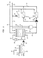
- Figure 1 is a simplified flowsheet of a membrane-bioreactor system schematically showing its operation with two ultrafiltration modules, and the essential permeate recycle.
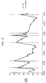
- Figure 2 is a graph showing the variation of membrane flux as a function of time.
- Figure 3 is a graph showing the build-up of suspended solids in the bioreactor due to inert solids over nearly a year, at various levels of inert solids concentration in the wastewater feed (g/L).
- the membrane-bioreactor system is intended for use by those concerned with the cost of treating wastewater generated in a metal-working plant effectively.
- this wastewater is a relatively small volume compared to the volume of biodegradable waste generated by a metropolitan area, the difficulty of disposing of it requires that it be disposed of by the operators of the plant.
- the delivered wastewater from such a plant cannot be treated in a municipal sewage disposal facility because of the poor biodegradability of waste fluids in the wastewater.
- k After establishing the SRT deemed necessary to achieve a given effluent quality, along with values for Y and b, or Yn, k can be determined. With k known, the required reactor volume can be determined from values for the reactor VSS and feed and effluent concentration values.
- the SRT and HRT of an optimal reactor depends on the molecular size of the wastewater components and reaction products, the biological and chemical (hydrolysis reactions) treatability characteristics of the wastewater components, the inhibitory nature of the reaction products, and the membrane characteristics with respect to effective pore size.
- A Q/J
- A total membrane area required
- m 2 and, J membrane flux, m 3 /m 2 -day.
- J depends on such factors as the reactor TSS, surface velocity, temperature, transmembrane pressure drop, surface fouling and the extent of concentration polarization. Concentration polarization arises from the accumulation of solutes on the membrane surface. Solutes reach the membrane surface by convective transport of the solvent, a portion of which passes through the membrane. The rejected solutes often form a viscous gel layer on the membrane. This gel layer acts as a secondary membrane reducing the flux and often reducing the passage of low molecular weight solutes.
- a bioreactor 10 which contains an aqueous suspension 12 of live microorganisms which have been especially acclimated to ingest the waste fluids as nutrients, albeit with the deliberate addition of other "added” nutrients such as phosphate and nitrogenous compounds.
- the nutrient value of the waste fluids is typically so poor as to require continuous addition of the added nutrients to help the microorganisms ingest the waste fluids.
- Such microorganisms are commercially available.
- the bioreactor operates at atmospheric pressure; it is provided with a sparger 14 through which air or oxygen required to maintain the microorganisms, is distributed from conduit 13 uniformly throughout the reactor.
- the reactor includes baffle means to improve contacting the waste fluids with the microorganisms.
- Delivered wastewater is introduced through line 15 into an equalization tank 20 which, in addition to equalizing the flow to the reactor, also serves as a settling tank for the removal of settled solids through line 17, and the removal of free oil through line 11.
- Free oil and grease "skim" 16 float to the surface and are skimmed off.
- Solids 17 settle and are either periodically or continuously removed from the bottom of the settling tank, depending upon the level of solids in the delivered wastewater, and disposed of.
- the aqueous suspension of wastewater from the settling tank 20 is withdrawn through line 21 and 22 before it is led to the suction side of a feed pump 24 which operates at low pressure to pump the aqueous suspension of equalized wastewater through about a 106 ⁇ m filtration unit 26.
- the filtered aqueous suspension is then led through conduit 23 into the bioreactor 10.
- Feed to the bioreactor 10 is maintained essentially constant so as to maintain a predetermined concentration of solids in the mass 12, and liquid level in the bioreactor.
- a stream of the contents 12 of the bioreactor is withdrawn through pump suction line 27 and discharged as a pressurized stream by pressurization pump 28 through a discharge line 29 to a membrane filtration unit indicated generally by reference numeral 30.
- a membrane filtration unit 30 having two or more ultrafiltration modules 31 and 32 connected in parallel, in each of which the membrane has a pore size smaller than 0.5 ⁇ m, and to maintain operation of the membrane unit 30 with a clean water flux (measured at 20°C and 40 psig or 370 kPa abs) of at least 10 m 3 /m 2 /day.
- Permeate from the membrane unit 30 is removed from the system through permeate recycle conduit 33, while concentrate leaves through concentrate recycle conduit 35.
- the outlet pressure of the concentrate in line 29 is in the range from about 250 kPa (25 psig) to about 1000 kPa (125 psig) depending upon the configuration of the modules and layout of the membrane units.
- a major portion, preferably more than 95% by volume, of the concentrate stream flowing through conduit 35 is recycled as recycle stream 37 and the remainder 37' purged through purge line 37.
- a minor portion, preferably from about 0.1% to 30% by volume, of the permeate stream flowing through conduit 33 is recycled as recycle stream 39 and the remainder withdrawn as treated effluent through effluent line 39'.
- the volume of effluent permeate removed through line 39' will depend upon the physical characteristics of the reaction mass as well as the specifications of the membrane. Typically the effluent stream 33 will range from about 0.5% by volume or even less, to about 3% by volume of the pressurized bioreactor contents stream 29.
- the portion 39 of the permeate recycled to the bioreactor maintains a balance between incoming feed to the membrane device and removed effluent.
- a portion of the recycle streams 37 and 39 may be diverted to a cleaning tank 40 through conduits 41 and 43 respectively, and used to wash and chemically clean the membranes when required.
- One or more chemicals addition tanks 44 are provided to supply acid and alkali for pH control, and various nutrients, for example phosphate, to supplement the nutrients provided to the biomass by the waste fluids.
- Pump(s) 45 meter the appropriate chemical(s) when desired.
- a membranous filtration unit preferably has a pore size in the range from about 0.001 ⁇ m to about 0.05 ⁇ m, but may be larger, from about 0.01 ⁇ m to about 0.1 ⁇ m, if lesser quality effluent is acceptable.
- Preferred membranes for microfiltration are derived from poly(vinyl alcohol), polysulfone, polypropylene, nylon and the like, for example Zenon SJ.
- the same materials may be used to provide ultrafiltration membranes, for example a Zenon TAM membrane.
- the bacteria found to be effective in the process are commonly found in activated sludge and include the genera Pseudomonas, Zooglea, Achromobacter, Flavobacter, Nocardia, Bdellovibrio, and Mycobacter, normally all considered heterotrophic. These perform the bulk of the bio-stabilization.
- the autotrophic bacteria which may be present are represented by Nitrosonomas and Nitrobacter, both nitrogen fixing. Also found in activated sludge are a variety of fungus, yeasts and protozoa, some of which are also useful in our process.
- a 3.78 m 3 (1000 gal) bioreactor is operatively connected with a variable module, multi-tube membrane unit of Zenon Z8 modules with HSC or TAM membranes.
- Each module contained 8 1.83 m long by 2.22 cm diameter tubes connected in series to provide a membrane area of 0.975 m 2 /module.
- the modules themselves were connected in parallel with the concentrate recycle to the bioreactor, and with the permeate being recycled to the bioreactor and being removed as effluent.
- a liquid level control system maintains the reactor volume within 11 percent of the mean reactor volume. Enough air was introduced into the reactor to provide complete mixing and aerobic conditions for growth of the biomass.
- the daily mean dissolved oxygen (DO) concentration in the reactor was in the range from 0.5 to 6.1 mg/L.
- the reactor pH ranged from 6.8 to 7.9.
- the ratio of concentrate recycle Q c to permeate flow Q p is maintained at about 120.
- the concentration of solids in the concentrate recycle line is essentially the same as that in the bioreactor.
- the reactor pH was maintained near neutral by addition of sulfuric acid. Automatic pH control is maintained with a set point of 7.5.
- a further reduction in accumulation of high mol wt, soluble and non-reactive compounds can be achieved by using a more open membrane such as the Zenon TAM membrane, than the Zenon HSC membrane used for the other runs.
- Solids balances were completed across the membrane system at each equilibrium condition in order to determine biomass net yield coefficients.
- the low yield values observed are attributable to the long SRTs used in this process. These values are set forth in Table V below.
- the mass balance information can be used to estimate the solids produced per volume of wastewater treated in the system. A value of 0.21 kg/m 3 (1.78 lb/1000 gal) of wastewater treated was determined, based on the average net yield value observed. This value is less than 10% of the solids that would be produced from a conventional physical-chemical oily wastewater treatment system with conventional add-on biological treatment. TABLE IV. Effect on MBR system performance of using a more open membrane in ultrafiltration unit.
- the membrane flux of the unit was approximately 100 L/m 2 -hr (59 gal/ft 2 -day) upon start-up of the system. The flux declined rapidly over approximately the first forty days and after that, averaged between 40 - 50 L/m 2 -hr. The membranes were cleaned with alkali every one or two weeks to restore the flux to approximately 60 L/m 2 -hr.
- the membrane unit was operated until day 196 with minimal back pressure exerted on the membranes by the discharge pressure control valve.
- the pressure at the exit of the membrane unit was less than 70 kPa (10 psig).
- the pressure was increased to 140 kPa (20 psig) to bring the system in line with anticipated full scale operating conditions. As a result of the increase of pressure there was also a 14-20% increase in flux.
Landscapes
- Chemical & Material Sciences (AREA)
- Chemical Kinetics & Catalysis (AREA)
- Life Sciences & Earth Sciences (AREA)
- Engineering & Computer Science (AREA)
- Physics & Mathematics (AREA)
- Thermal Sciences (AREA)
- Water Supply & Treatment (AREA)
- Organic Chemistry (AREA)
- Hydrology & Water Resources (AREA)
- Environmental & Geological Engineering (AREA)
- Biodiversity & Conservation Biology (AREA)
- Microbiology (AREA)
- General Chemical & Material Sciences (AREA)
- Oil, Petroleum & Natural Gas (AREA)
- Health & Medical Sciences (AREA)
- Toxicology (AREA)
- Combustion & Propulsion (AREA)
- Separation Using Semi-Permeable Membranes (AREA)
- Activated Sludge Processes (AREA)
- Fats And Perfumes (AREA)
Abstract
Description
- Operation of an aerobic bioreactor is highly sensitive to the composition of wastewater treated and the time within which treatment is to be completed. Stated differently, given enough time and no reasonable constraint on the expenditure of energy, the challenge to operate a waste treatment system would be de minimis. Since the challenge is to provide a system which economically satisfies the time-energy sensitivity of its operation, the emphasis in the art is to provide the most efficient means to maintain the activity of a biomass by transferring as much oxygen into the bioreactor's reaction mass (aqueous suspension of biomass, namely, of organic solids and microorganisms) as can be used by microorganisms to biodegrade biochemically oxidizable material. To be commercially acceptable, this must be done within a reasonable period of time, using a small amount of energy, to produce treated water of acceptably high quality. The high difficulty of evaluating such a system with a laboratory bench scale apparatus, led to the testing of the system in a pilot plant on the grounds of the NDH Sandusky automobile plant of General Motors Corp. Wastewater from a Mansfield General Motors plant was also trucked over to the pilot plant for testing because there was a substantial variation in the composition of the wastewater from the two plants.
- More specifically, this invention relates to treating a mixture of natural hydrocarbon and synthetic metal-working fluids, fats, oils and greases ("FOG") mixed with synthetic organic and organometallic compounds, some of which are insoluble solids, others emulsifiable liquids, and still others soluble solids and liquids. This mixture in wastewater is referred to herein as "waste fluids". Waste fluids comprise particularly difficult-to-treat components and relatively easy-to-treat components.
- The problem is to provide a process which will biologically degrade waste fluids in a wastewater stream which varies from one hour to the next, economically. The stream varies both in mass flow per hour, and in the concentration of waste fluids therein. The problem to be solved is to use a membrane separator which typically operates with constant mass flow per hour, in conjuction with a bioreactor, to provide an effluent which will meet governmental compliance requirements. Further, the ratios of the components of the waste fluids varies during operation. Yet, a successful process requires that it operates essentially continuously substantially without human attention. Still further, the waster production from the process is to be minimized.
- The foregoing problems are solved by the process as set out in claims 1 to 12 and by the apparatus for carrying out this process, as defined in
claims 13 to 15. - A determinative factor was specifying the system so as to generate permeate at a rate greater than that at which solids-depleted feed is introduced to the reactor. This high rate of permeate production makes it possible to provide a permeate recycle, in addition to the recycle of biomass in concentrate. Despite the apparent contradiction of recycling the permeate after going to the trouble of generating it, the permeate recycle is essential for the reactor to operate at constant volume, and to feed a membranous ultrafiltration zone at a constant rate of flow. The reason for the permeate recycle is explained in detail herebelow.
- The process incorporates the claimed features and relies upon the unique operation, in combination, of an ambient pressure aerobic reactor, an equalization tank, and a membrane device tailored to let pass through it, a predetermined amount and size of molecules which are the product of biodegradation.
- Wastewater delivered ("delivered wastewater") is pretreated to remove floatable free oil and settleable solids prior to transfer into an equalization tank. One example of a pretreatment device is a corrugated plate interceptor (CPI) although any other devices suitable for removing floatable oils and settleable solids may be used. Alternatively, the removal of floatable free oils and settleable solids may be performed in the equalization tank directly, with suitable equipment. The feed to the bioreactor is taken from the equalization tank and contains FOG having chemical and physical properties quite unlike wastewater containing waste generated by human activities, typical of municipal wastewater. In particular, wastewater from metal-working operations contain any or all of the following constituents: petroleum-based (oil-based) FOG; non-petroleum based (synthetic or semi-synthetic oils) FOG; and organometallic compounds. These constituents vary in biodegradability across the full spectrum of difficulty. It is this feed which was treated in a membrane bioreactor system which was extensively tested at the NDH General Motors automobile plant, in the pilot plant tests which were reported in an oral presentation on October 10, 1990 at the WPCF Conference in Washington, D.C.
- The basic technology, using a bioreactor with a membrane separator, was disclosed a quarter of a century ago in U.S. Patent No. 3,472,765 to Budd et al. They used a well-aerated bioreactor in combination with a microfiltration or an ultrafiltration membrane, not only to avoid the time penalty of gravity settling technology but also to provide essentially solid-free water of high quality ("permeate") to be recovered and the remaining undegraded high molecular weight materials and solids-containing stream ("concentrate") recycled to the bioreactor.
- The essential process characteristic of the '765 process was that it maintained a constant reactor volume by varying the feed flow. Further, the organic solids were comminuted but not removed, so they remained in the recycled concentrate. In contrast, the process of our invention maintains a constant reactor volume by maintaining the flow rate of feed to the reactor essentially constant, and, recycling both concentrate and permeate. In our process, essentially no solids greater than about 106µm enter the reactor, and the only solids in the system are the aforementioned finely divided organic solids, the biomass itself, and the products that biomass generates.
- The '765 system was commercialized with limited success in the 70's mainly with respect to human and animal waste, such success arising in applications which were not cost-sensitive. The operation of such a system with delivered wastewater containing waste fluid with FOG from a metal-working plant was unsuccessful because the solids retention time (SRT) and the hydraulic retention time (HRT) were not long enough to degrade the waste fluid.
- Though each mechanical component in the system is known, the combination used in our process is found to be effective if operated as described hereunder to treat delivered wastewater which contains a very high concentration of FOG. The bioreactor is operated to maintain a predetermined concentration of FOG and total suspended solids ("TSS"), and the membrane device is operated as an ultrafiltration membrane at low pressure, in the range from about 170 to 1035 Kpa (25 psig to 150 psig). Such operation results in a controlled high mass flow of solids-containing concentrate as a recycle stream.
- The mass flow from the bioreactor is surprisingly high, yet (i) provides a long solids retention time (SRT), and enough liquid as is required per unit of air entrained, to degrade the FOG in delivered wastewater, and also (ii) completes degradation of the organic waste with a hydraulic retention time of less than 5 days, preferably less than 48 hr, in the bioreaction system. The key to providing the foregoing is to retain emulsified pollutants for a period longer than the liquid residence time or hydraulic retention time (HRT) of the reactor, based on the wastewater flow rate.
- It has been discovered that operation of a bioreactor system including an aerobic bioreactor in combination with a membrane filtration device will successfully degrade delivered wastewater containing high concentrations of natural, synthetic and semi-synthetic metal-working fluids, fats, oils and greases (together "FOG" for brevity) used in a metal-working plant, only if the system is operated within a narrowly defined window of operating criteria. The wastewater is first skimmed and settlable solids removed. In particular, because the waste fluid contains poorly degradable solids and a high concentration of "FOG", all except very finely divided solids, are removed, preferably in a filtration zone equipped with a 106 µm screen. This pretreated wastewater allows the bioreactor in combination with an ultrafiltration membrane means, to be operated with a hydraulic retention time (HRT) of at least 24 hr, preferably from 1 to 5 days, and a solids retention time (SRT) in the range from about 30-150 days, preferably from 50-125 days.
- The foregoing and additional objects and advantages of the invention will best be understood by reference to the following detailed description, accompanied with a schematic illustration of a preferred embodiment of the invention, in which :
- Figure 1 is a simplified flowsheet of a membrane-bioreactor system schematically showing its operation with two ultrafiltration modules, and the essential permeate recycle.
- Figure 2 is a graph showing the variation of membrane flux as a function of time.
- Figure 3 is a graph showing the build-up of suspended solids in the bioreactor due to inert solids over nearly a year, at various levels of inert solids concentration in the wastewater feed (g/L).
- In a preferred embodiment the membrane-bioreactor system is intended for use by those concerned with the cost of treating wastewater generated in a metal-working plant effectively. Though this wastewater is a relatively small volume compared to the volume of biodegradable waste generated by a metropolitan area, the difficulty of disposing of it requires that it be disposed of by the operators of the plant. The delivered wastewater from such a plant cannot be treated in a municipal sewage disposal facility because of the poor biodegradability of waste fluids in the wastewater.
- It will be recognized that, typically, it is of little concern whether a reactor operates at essentially constant volume with essentially constant feed, or a variable feed. By "essentially constant" we mean ±10%. However, to keep reactor volume constant with varying flow rate of feed, the membrane area has to be based on minimum flux observed during a cycle. Thus, to treat 1000 L/hr ("Q") of feed with membranes having a minimum flux rate of 100 L/m2-hr ("F"), the membrane area ("A") required is 10 m2. However, the reactor volume ("V") has to be based on maximum flux, since the reactor must contain enough wastewater to be flowed to the membranes when they are operating at maximum flux. Assuming the maximum flux is twice the minimum, that is, 200 L/m2-hr, and the minimum HRT required to degrade the waste is 24 hr, then

- With constant feed flow rate in a reactor operating at constant volume, as in our system, the required membrane area is based on minimum flux, as before, and is 10 m2. But the reactor volume is based on minimum flux 100 L/m2-hr, since feed flow is constant and both concentrate and permeate are recycled, so the volume of the reactor now required is

- In a commercial system which requires that a feed flow rate of 1000 L/hr be treated, it makes a significant economic difference whether the reactor is to be twice the volume it could be.
- As stated hereabove, it was found that once free oil and the incoming solids were removed from the delivered wastewater, successful biodegradation of the feed to the bioreactor depended upon maintaining a high enough SRT and HRT, and at the same time being able to accommodate normal flux fluctuation during a cycle before cleaning of the membrane, without substantially sacrificing the average flux obtained during the cycle.
- In a typical situation, faced with having to do the foregoing, one can either (a) raise the pressure of the stream delivered to the membranes of the number of modules required to provide a desired permeate flow which, at equilibrium operating conditions, is equal to the flow Qf of feed; or, (b) one can provide a larger number of modules than needed so that one can operate the modules under substantially constant pressure of the incoming stream because the flux of the membranes remains substantially constant.
- Though not immediately evident, one finds that increasing the pressure to maintain the flux across the membranes of a module, soon results in the use of a pressure which is so high as to entail an unacceptably high risk of failure of a membrane.
- The other alternative, namely using much more membrane area than required in the preceding embodiment, results in production of a large amount of permeate which is greater in mass flow per unit time, than Qf. Since this would result in depletion of the liquid content of the reactor, a portion Qp1 of the permeate produced in the modules, preferably a minor thereof, is recycled, the remainder Qp2 being withdrawn.
- Under steady state conditions, the relationship between microbial growth and substrate removal may be expressed as:

- µ = organism specific growth rate, mass/mass-time,
- Y = organism yield coefficient, mass/mass,
- K = specific substrate utilization rate, mass/mass-time
- and, b = organism decay coefficient, time-1.
- After establishing the SRT deemed necessary to achieve a given effluent quality, along with values for Y and b, or Yn, k can be determined. With k known, the required reactor volume can be determined from values for the reactor VSS and feed and effluent concentration values. The SRT and HRT of an optimal reactor depends on the molecular size of the wastewater components and reaction products, the biological and chemical (hydrolysis reactions) treatability characteristics of the wastewater components, the inhibitory nature of the reaction products, and the membrane characteristics with respect to effective pore size.
- Once a minimum membrane flux is specified, the corresponding minimum membrane area (A) can be calculated as:

A = total membrane area required, m2
and,
J = membrane flux, m3/m2-day. J depends on such factors as the reactor TSS, surface velocity, temperature, transmembrane pressure drop, surface fouling and the extent of concentration polarization. Concentration polarization arises from the accumulation of solutes on the membrane surface. Solutes reach the membrane surface by convective transport of the solvent, a portion of which passes through the membrane. The rejected solutes often form a viscous gel layer on the membrane. This gel layer acts as a secondary membrane reducing the flux and often reducing the passage of low molecular weight solutes. Surface fouling is the result of the deposition of submicron particles on the surface as well as the accumulation of smaller solutes due to such processes as crystallization and precipitation. It is this deterioration in membrane flux which is counteracted by using a larger membrane area than is necessary, and by recycling permeate to the bioreactor. - Referring to Fig 1 there is shown a
bioreactor 10 which contains anaqueous suspension 12 of live microorganisms which have been especially acclimated to ingest the waste fluids as nutrients, albeit with the deliberate addition of other "added" nutrients such as phosphate and nitrogenous compounds. The nutrient value of the waste fluids is typically so poor as to require continuous addition of the added nutrients to help the microorganisms ingest the waste fluids. Such microorganisms are commercially available. The bioreactor operates at atmospheric pressure; it is provided with asparger 14 through which air or oxygen required to maintain the microorganisms, is distributed fromconduit 13 uniformly throughout the reactor. The reactor includes baffle means to improve contacting the waste fluids with the microorganisms. - Delivered wastewater is introduced through
line 15 into anequalization tank 20 which, in addition to equalizing the flow to the reactor, also serves as a settling tank for the removal of settled solids throughline 17, and the removal of free oil through line 11. Free oil and grease "skim" 16 float to the surface and are skimmed off.Solids 17 settle and are either periodically or continuously removed from the bottom of the settling tank, depending upon the level of solids in the delivered wastewater, and disposed of. The aqueous suspension of wastewater from the settlingtank 20 is withdrawn throughline 21 and 22 before it is led to the suction side of afeed pump 24 which operates at low pressure to pump the aqueous suspension of equalized wastewater through about a 106 µm filtration unit 26. The filtered aqueous suspension is then led throughconduit 23 into thebioreactor 10. - Feed to the
bioreactor 10 is maintained essentially constant so as to maintain a predetermined concentration of solids in themass 12, and liquid level in the bioreactor. - A stream of the
contents 12 of the bioreactor is withdrawn throughpump suction line 27 and discharged as a pressurized stream bypressurization pump 28 through adischarge line 29 to a membrane filtration unit indicated generally byreference numeral 30. - It is preferred, in a commercial unit, to use a
membrane filtration unit 30 having two ormore ultrafiltration modules membrane unit 30 with a clean water flux (measured at 20°C and 40 psig or 370 kPa abs) of at least 10 m3/m2/day. - Permeate from the
membrane unit 30 is removed from the system through permeate recycleconduit 33, while concentrate leaves throughconcentrate recycle conduit 35. The outlet pressure of the concentrate inline 29 is in the range from about 250 kPa (25 psig) to about 1000 kPa (125 psig) depending upon the configuration of the modules and layout of the membrane units. - A major portion, preferably more than 95% by volume, of the concentrate stream flowing through
conduit 35 is recycled asrecycle stream 37 and the remainder 37' purged throughpurge line 37. A minor portion, preferably from about 0.1% to 30% by volume, of the permeate stream flowing throughconduit 33 is recycled asrecycle stream 39 and the remainder withdrawn as treated effluent through effluent line 39'. - The volume of effluent permeate removed through line 39' will depend upon the physical characteristics of the reaction mass as well as the specifications of the membrane. Typically the
effluent stream 33 will range from about 0.5% by volume or even less, to about 3% by volume of the pressurized bioreactor contents stream 29. Theportion 39 of the permeate recycled to the bioreactor maintains a balance between incoming feed to the membrane device and removed effluent. - If desired, a portion of the recycle streams 37 and 39 may be diverted to a
cleaning tank 40 throughconduits chemicals addition tanks 44 are provided to supply acid and alkali for pH control, and various nutrients, for example phosphate, to supplement the nutrients provided to the biomass by the waste fluids. Pump(s) 45 meter the appropriate chemical(s) when desired. - A membranous filtration unit preferably has a pore size in the range from about 0.001 µm to about 0.05 µm, but may be larger, from about 0.01 µm to about 0.1 µm, if lesser quality effluent is acceptable.
- Preferred membranes for microfiltration are derived from poly(vinyl alcohol), polysulfone, polypropylene, nylon and the like, for example Zenon SJ. The same materials may be used to provide ultrafiltration membranes, for example a Zenon TAM membrane.
- Referring to Fig 2 it is evident that the modules operated for over a year without having to be replaced. For the specific membrane modules tested, the flux varied over more than a two-fold range from about 27.1 L/m2-hr to 71.2 L/m2-hr (about 16 gals/ft2-day to 42 gals/ft2-day). It is this large variation in flux which is accommodated by the permeate recycle, allowing the reactor to operate at essentially constant volume, with an essentially constant rate of feed, and having an essentially constant rate of suspended solids withdrawn from the reactor and flowed to the membrane modules. The desired output of high quality effluent could thus be maintained.
- The sensitivity of the reactor to the presence of inert solids such as non-degradable silicon carbide and metal particles at various concentrations of solids present, over a period of nearly a year, is graphically demonstrated in Fig 3. The reactor operated at HRT = 2 days, and a SRT = 40 days. It will be evident that the steep rise of the build-up with increasing concentration of solids will adversely affect the effectiveness of the membrane modules, not only in terms of their flux, but because such inorganic solids have an abrasive action at the velocities required. Such abrasive action can easily damage a membrane requiring that the damaged module be correctly identified and replaced.
- The bacteria found to be effective in the process are commonly found in activated sludge and include the genera Pseudomonas, Zooglea, Achromobacter, Flavobacter, Nocardia, Bdellovibrio, and Mycobacter, normally all considered heterotrophic. These perform the bulk of the bio-stabilization. The autotrophic bacteria which may be present are represented by Nitrosonomas and Nitrobacter, both nitrogen fixing. Also found in activated sludge are a variety of fungus, yeasts and protozoa, some of which are also useful in our process.
- In a pilot plant operation, a 3.78 m3 (1000 gal) bioreactor is operatively connected with a variable module, multi-tube membrane unit of Zenon Z8 modules with HSC or TAM membranes. Each module contained 8 1.83 m long by 2.22 cm diameter tubes connected in series to provide a membrane area of 0.975 m2/module. The modules themselves were connected in parallel with the concentrate recycle to the bioreactor, and with the permeate being recycled to the bioreactor and being removed as effluent. A liquid level control system maintains the reactor volume within 11 percent of the mean reactor volume. Enough air was introduced into the reactor to provide complete mixing and aerobic conditions for growth of the biomass.
- The daily mean dissolved oxygen (DO) concentration in the reactor was in the range from 0.5 to 6.1 mg/L. The reactor pH ranged from 6.8 to 7.9. The ratio of concentrate recycle Qc to permeate flow Qp is maintained at about 120. The concentration of solids in the concentrate recycle line is essentially the same as that in the bioreactor. Membrane-Bioreactor System Start-up: The reactor is seeded with biomass together with a small amount of nutrients (nitrogen, phosphorus, potassium) if required, to support biomass growth, and air flow was adjusted to maintain an excess concentration of dissolved oxygen. The reactor pH was maintained near neutral by addition of sulfuric acid. Automatic pH control is maintained with a set point of 7.5.
- In several pilot plant runs made with representative wastewater feed taken from two metal-working facilities, the bioreactor was operated with target pilot plant SRT (days) in the range from 50 to 100, and with HRT (days) in the range from 1.87 and 3.74. The performance of the system was assessed by sampling several locations and analyzing for particulate and soluble components. Analyses for NH3-N, total Kjeldahl nitrogen (TKN), and total phosphorus (TP) were less frequent than the analyses for other analytical parameters.
- Operating conditions for runs are presented in Table I below. The performance results are summarized in Table II below. In Table II, experiments P2-1, P2-2 and P2-3 indicate that even longer SRT and HRT conditions than for other runs, provide a further improved effluent quality. Note that the accumulation of non-reactive compounds in the reactor do not appear to result in microbial inhibition at least to the extent that the degree of nitrification or ammonia reduction across the membrane is affected. This is evidenced by the generally low values of NH3-N in the effluent.
- In Table III below are listed soluble reactor values (passing 0.45µ filter paper) vs. effluent COD values. The extent of accumulation of non-reactive compounds is lower for a SRT of 100 days than for 50 SRT days.


- The extent of degradation of slowly degradable high mol wt soluble compounds in the feed exceeds the build-up of high mol wt chemical or biological products as the SRT is further increased from 50 days to 100 days.
- A further reduction in accumulation of high mol wt, soluble and non-reactive compounds can be achieved by using a more open membrane such as the Zenon TAM membrane, than the Zenon HSC membrane used for the other runs.
- A side-by-side comparison of the results obtained with the HSC and TAM membranes is presented in Table IV below. In run P3-2 a COD value equivalent to 7% of the feed concentration appeared in the effluent representing microbial metabolites or highly recalcitrant feed material. During the TAM membrane run, this value increased to about 11%. Therefore, as might be expected, a higher effluent COD is obtained with a more open membrane than a less open one, using wastewaters containing equal levels of organic/inorganic constituents.
- Solids balances were completed across the membrane system at each equilibrium condition in order to determine biomass net yield coefficients. The low yield values observed are attributable to the long SRTs used in this process. These values are set forth in Table V below. The mass balance information can be used to estimate the solids produced per volume of wastewater treated in the system. A value of 0.21 kg/m3 (1.78 lb/1000 gal) of wastewater treated was determined, based on the average net yield value observed. This value is less than 10% of the solids that would be produced from a conventional physical-chemical oily wastewater treatment system with conventional add-on biological treatment.
TABLE IV. Effect on MBR system performance of using a more open membrane in ultrafiltration unit. CPC Mansfield Wastewater Parameter HSC membrane (Run P3-2) TAM membrane (day 271 to day 287) Equilibrium Reactor Operating Conditions HRT, days 1.87 1.87 SRT, days 100 100a System Performance Results Feed Values, mg/l COD 5937 3415 BOD5 1043 600 TSS 410 331 Total FOG 788 386 Hydrocarbon based FOG 403 225 TKN 43 27 Effluent Values, mg/l COD 417 386 BOD 521 20 TSS 1 2 Total FOG 16 15 Hydrocarbon based FOG 5 5 NH4-N 0.8 0.4 * Actual SRT in reactor during operation with TAM membranes is estimated between 50 and 100 days. Calculating actual value complicated by unplanned solids wasting. 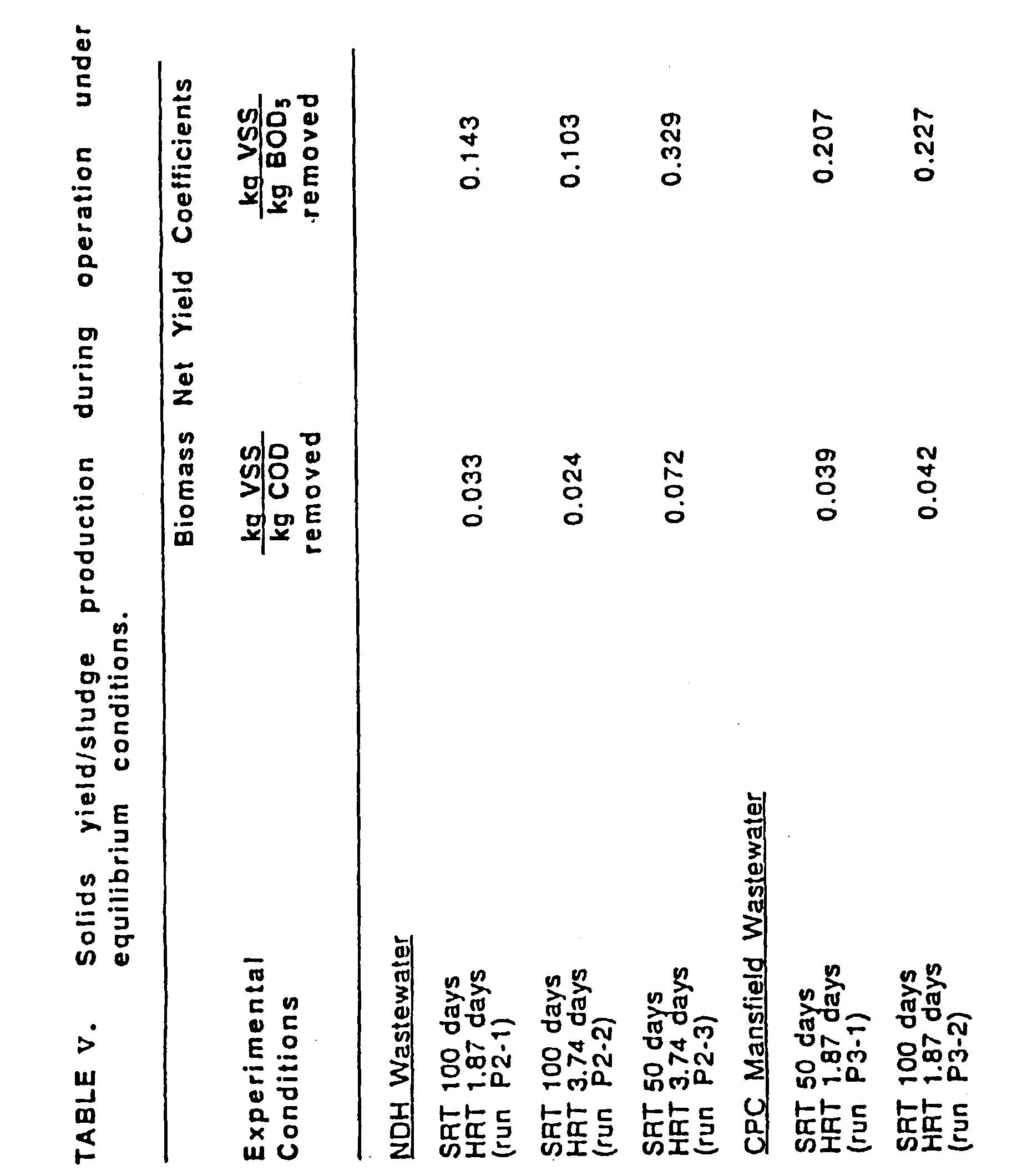
- Ultrafiltration Unit Design and Performance: The membrane flux of the unit was approximately 100 L/m2-hr (59 gal/ft2-day) upon start-up of the system. The flux declined rapidly over approximately the first forty days and after that, averaged between 40 - 50 L/m2-hr. The membranes were cleaned with alkali every one or two weeks to restore the flux to approximately 60 L/m2-hr.
- The membrane unit was operated until day 196 with minimal back pressure exerted on the membranes by the discharge pressure control valve. The pressure at the exit of the membrane unit was less than 70 kPa (10 psig). On day 196, the pressure was increased to 140 kPa (20 psig) to bring the system in line with anticipated full scale operating conditions. As a result of the increase of pressure there was also a 14-20% increase in flux.
- Operation of the pilot plant led to the conclusion that the system described and operated as specified, is able to treat the specified wastewater with the specific waste fluids typically present in such a stream from a metal-working facility such as an automotive plant from which the wastewater samples treated were obtained, and provide effluent with the following specification:
- Chemical Oxygen Demand, COD < 450 mg/L;
- Biological Oxygen Demand, BOD5 < 25 mg/L;
- Total suspended solids, TSS < 10 mg/L;
- Total FOG < 25 mg/L; and NH3-N < 1.0 mg/L.
- It will now be evident that the long SRTs and HRTs for this process are quite unlike those used in a conventional bioreactor for typical organic waste, such as used in the '765 bioreactor. Typical SRTs for a '765 system range from 1 to 5 days and the HRTs range from about 0.5 hr to 3 hr. The very long times used in our process are surprisingly accommodated by the specific features of the process which target wastewater containing waste fluids which are difficult to biodegrade. Nevertheless, they are usable as nutrients for the biomass we use provided of course, the process is operated as specified.
- Having thus provided a general discussion, described the overall process in detail and illustrated the invention with specific examples of the best mode of carrying out the process, it will be evident that the invention has provided an effective solution to a difficult problem.


Since the VSS lost in the effluent is negligible and solids are wasted directly from the reactor, the system SRT can be expressed as

V = reactor volume, m3
and,
W = reactor volume wastage rate, m3/hr.
The SRT is controlled by wasting a predetermined volume of the contents of the reactor, per day.
Claims (13)
- A continuous process for treating wastewater containing difficult-to-biodegrade waste fluids, in particular waste fluids from a metal-working plant, in a bioreaction zone containing a suspension of biomass including live microorganisms adapted to biodegrade components of said waste fluids, comprising :(a) removing free oil and finely divided solids injurious to membranes from delivered wastewater to provide a solids-depleted feed substantially free of free oil;(b) maintaining the rate of flow of solids-depleted feed to said bioreaction zone essentially constant, while maintaining said bioreaction zone with a solids retention time (SRT) of at least 30 days, and a hydraulic retention time (HRT) of at least 1 day;(c) removing an aqueous suspension from said bioreaction zone to a membranous filtration zone from which permeate is recovered at a rate greater than the rate of solids-depleted feed;(d) flowing said suspension through said membranous filtration zone at a velocity and pressure sufficient to maintain a predetermined membrane flux in the membranous filtration zone, at which flux essentially no solids are retained on the surface of membrane in the filtration zone;(e) separating permeate from a solids-containing concentrate;(f) flowing said solids-containing concentrate as a concentrate recycle from said membranous filtration zone into the bioreaction zone;(h) removing an effluent of acceptable quality; and(i) flowing excess permeate over that removed as effluent, back to said bioreaction zone to maintain a substantially constant operating liquid throughput in the reactor.
- The process of claim 1, wherein the flow of said excess permeate to said bioreaction zone is a minor proportion by volume of said permeate removed as effluent.
- The process of claim 1 or 2, including maintaining said bioreaction zone with a solids retention time (SRT) in the range from 30 to 150 days, and a hydraulic retention time (HRT) in the range from 1 to 5 days.
- The process of claim 1, 2 or 3, wherein the wastewater is introduced via a pretreatment zone having a volume sufficiently large to equalize variations in the flow rate of said wastewater to said pretreatment zone where settlable solids and skimmable free oil are removed.
- The process of any preceding claim, comprising periodically removing a minor proportion by volume of said concentrate recycle to modulate the solids content in said bioreaction zone.
- The process of any preceding claim, wherein the removed finely divided solids are greater than about 106 µm in diameter.
- The process of any preceding claim, wherein the treated waste fluids is a solids-containing mixture of easy- and difficult-to-degrade waste fluids comprising organometallic compounds, natural, petroleum-based, synthetic and semi-synthetic fats, oils and greases used in machining operations in a metal-working plant.
- The process of claim 7, wherein said effluent has at least the following specifications:Chemical Oxygen Demand, COD < 450 mg/L;Biological Oxygen Demand, BOD5 < 25 m/L;Total suspended solids, TSS < 10 mg/L;Total FOG < 25 mg/L; and NH3-N < 1.0 mg/L;wherein FOG represents fats, oils and greases.
- The process of claim 8, wherein said membranous filtration zone is operated at a pressure in the range from 170 kPa to 1035 kPa gauge, insufficient to affect membranes in said zone deleteriously.
- The process of any preceding claim, wherein said membranous filtration zone has a membrane area of at least 10 m2.
- The process of any preceding claim, wherein said bioreaction zone contains bacterial cells greater than 0.5µm diameter and said separated permeate is essentially free of molecules having an effective diameter greater than 0.5µm.
- The process of any preceding claim, wherein said waste fluids comprise synthetic fluids, fats, oils and greases used in machining operations in a metal-working plant; said minor portion of permeate recycled is in the range from 0.1% to 30% by volume of the permeate withdrawn; and said permeate withdrawn as effluent is in the range from 0.5% to 3% by volume of said suspension of biomass withdrawn from said bioreaction zone.
- A wastewater treatment apparatus for carrying out the process acording to any of the preceding claims, which apparatus is operatively connected between a source of wastewater containing difficult-to-biodegrade waste fluids, in particular waste fluids from a metal-working plant, and an outlet for treated effluent, comprising,(a) a vessel (20) large enough to hold said wastewater delivered at a variable rate of flow and to equalize the rates of flow to a predetermined essentially constant rate removed from said vessel;(b) means (11) to remove free oil from said wastewater to provide a skimmed wastewater;(c) filtration means (26) having a mesh size small enough to remove finely divided solids injurious to membrane means and provide a solids-depleted feed;(d) a bioreactor (10) in which is confined an essentially constant volume of a reaction mass with means (13,14) for aerating skimmed and solids-depleted feed, and for contacting said feed with waste-degrading microorganisms mixed therein;(e) pump means (28) for withdrawing a suspension of biomass from said bioreactor at an essentially constant rate of flow, and impelling said suspension at elevated pressure;(f) membrane filtration means (30) in direct, open flow-receiving communication with said pump means, said membrane filtration means including plural membrane elements (31,32) adapted to separate said suspended solids in a concentrate stream (35), from water permeate which is essentially free of solids, and means (33) to duct said permeate away from said system;(g) means (37) to return said concentrate stream to said bioreactor (11); and,(h) means (39) to return a minor portion of said permeate to said bioreactor.
Applications Claiming Priority (3)
| Application Number | Priority Date | Filing Date | Title |
|---|---|---|---|
| US07/773,226 US5204001A (en) | 1991-10-09 | 1991-10-09 | Membrane bioreactor system for treating synthetic metal-working fluids and oil-based products |
| PCT/CA1992/000442 WO1993007092A1 (en) | 1991-10-09 | 1992-10-09 | Membrane bioreactor system for treating synthetic metal-working fluids and oil-based products |
| US773226 | 2004-02-09 |
Publications (2)
| Publication Number | Publication Date |
|---|---|
| EP0560980A1 EP0560980A1 (en) | 1993-09-22 |
| EP0560980B1 true EP0560980B1 (en) | 1997-12-17 |
Family
ID=25097586
Family Applications (1)
| Application Number | Title | Priority Date | Filing Date |
|---|---|---|---|
| EP19930906356 Expired - Lifetime EP0560980B1 (en) | 1991-10-09 | 1992-10-09 | Membrane bioreactor system for treating synthetic metal-working fluids and oil-based products |
Country Status (14)
| Country | Link |
|---|---|
| US (2) | US5204001A (en) |
| EP (1) | EP0560980B1 (en) |
| KR (1) | KR0177184B1 (en) |
| CN (1) | CN1075938A (en) |
| AU (1) | AU663893B2 (en) |
| CA (1) | CA2097716C (en) |
| CZ (1) | CZ112493A3 (en) |
| DE (1) | DE69223609T2 (en) |
| DK (1) | DK0560980T3 (en) |
| HU (1) | HU218749B (en) |
| PL (1) | PL299827A1 (en) |
| SK (1) | SK58393A3 (en) |
| TW (1) | TW278069B (en) |
| WO (1) | WO1993007092A1 (en) |
Cited By (1)
| Publication number | Priority date | Publication date | Assignee | Title |
|---|---|---|---|---|
| WO2009049401A1 (en) * | 2007-10-15 | 2009-04-23 | Seprotech Systems Incorporated | An integrated water processing technology |
Families Citing this family (39)
| Publication number | Priority date | Publication date | Assignee | Title |
|---|---|---|---|---|
| US5204001A (en) * | 1991-10-09 | 1993-04-20 | Zenon Environmental Inc. | Membrane bioreactor system for treating synthetic metal-working fluids and oil-based products |
| US5558774A (en) * | 1991-10-09 | 1996-09-24 | Zenon Environmental Inc. | Aerated hot membrane bioreactor process for treating recalcitrant compounds |
| US5403490A (en) * | 1992-11-23 | 1995-04-04 | Desai; Satish | Process and apparatus for removing solutes from solutions |
| JP2606156B2 (en) * | 1994-10-14 | 1997-04-30 | 栗田工業株式会社 | Method for collecting abrasive particles |
| EP0842123A1 (en) * | 1995-07-27 | 1998-05-20 | Helmut Prof. Dipl.-Ing. Hohnecker | Process for the biological decontamination of contaminated material |
| DE19613397C2 (en) * | 1996-04-03 | 2000-06-08 | Fraunhofer Ges Forschung | Process for the biological treatment of waste water |
| US6007712A (en) * | 1997-02-28 | 1999-12-28 | Kuraray Co., Ltd. | Waste water treatment apparatus |
| US6168712B1 (en) * | 1998-05-06 | 2001-01-02 | Kenko Sangyo Co., Ltd. | Apparatus for the biological treatment of waste fluid from the coating process |
| US6248985B1 (en) | 1998-06-01 | 2001-06-19 | Stericycle, Inc. | Apparatus and method for the disinfection of medical waste in a continuous manner |
| JP2000084567A (en) * | 1998-09-11 | 2000-03-28 | Fuji Heavy Ind Ltd | Treatment method for wastewater containing cutting oil |
| NL1013097C2 (en) * | 1999-09-20 | 2001-03-21 | Wijngaart Adriaan J Van Der | Manure processing and / or processing. |
| ES2197562T3 (en) * | 1999-10-26 | 2004-01-01 | Rochem Ultrafiltrations Systeme Gesellschaft Fur Abwasserreinigung Mbh | PROCEDURE AND DEVICE FOR THE DEPURATION AND / OR TREATMENT OF COMMUNAL AND / OR INDUSTRIAL WASTEWATER. |
| US6299766B1 (en) * | 2000-07-06 | 2001-10-09 | Clark Permar | Reverse osmosis filtering apparatus with concentrate dilution |
| US6706171B2 (en) | 2000-10-12 | 2004-03-16 | Biochem Technology, Inc. | Systems for treating wastewater in a series of filter-containing tanks |
| US6780318B2 (en) * | 2000-10-30 | 2004-08-24 | Jerome Jay Fife | Method for recovering a disposal trench with a biomat slime, and method for operating a waste treatment vessel |
| JP4318396B2 (en) | 2000-11-15 | 2009-08-19 | 株式会社日本触媒 | Method for producing porous crosslinked polymer material |
| FR2847572B1 (en) * | 2002-11-22 | 2006-04-21 | Omnium Traitement Valorisa | METHOD OF TREATING WATER USING INORGANIC HIGH SPECIFIC SURFACE PULVERULENT REAGENT INCLUDING A RECYCLING STAGE OF SAID REAGENT |
| US20040226887A1 (en) * | 2003-05-15 | 2004-11-18 | The Board Of Trustees Of The University Of Illinois | High percentage recovery method for purifying microemulsions |
| WO2006002529A1 (en) * | 2004-07-01 | 2006-01-12 | Zenon Technology Partnership | Screening apparatus for water treatment with membranes |
| US7455777B2 (en) * | 2004-12-14 | 2008-11-25 | Itt Manufacturing Enterprises, Inc. | Method of adjusting levels of dissolved compounds in beverages |
| US20080011693A1 (en) * | 2006-07-12 | 2008-01-17 | Ming Li | Self-cleaning waste-water device and method |
| WO2009023186A2 (en) * | 2007-08-10 | 2009-02-19 | Freije Treatment Systems, Inc. | Method and apparatus for treating a fluid |
| AT505926B1 (en) * | 2007-12-21 | 2009-05-15 | Va Tech Wabag Gmbh | Wastewater treatment plant and method for treating wastewater |
| US20090223891A1 (en) * | 2008-03-06 | 2009-09-10 | Ray Gauthier | System, device and method for on-site wastewater processing |
| CN101402492B (en) * | 2008-11-19 | 2011-06-29 | 北京桑德环境工程有限公司 | Wastewater treatment system and method for improving coefficient of recovery |
| CN101643300B (en) * | 2009-09-01 | 2012-01-04 | 浙江大学 | Treatment method of comprehensive waste water of metal processing |
| US20110192179A1 (en) * | 2010-02-05 | 2011-08-11 | Freije Iii William F | Evaporative heat transfer system and method |
| US8877064B2 (en) * | 2010-03-10 | 2014-11-04 | M-I L.L.C. | System and method for separating solids from fluids |
| EA201290893A1 (en) | 2010-03-10 | 2013-02-28 | Эм-Ай Эл.Эл.Си. | SYSTEM AND METHOD OF SEPARATION OF SOLID PARTICLES FROM LIQUIDS |
| CN101875518B (en) * | 2010-07-01 | 2011-08-31 | 陈启松 | Treatment method of stainless steel pickling waste water |
| CN102107993B (en) * | 2010-12-23 | 2014-08-20 | 郑高宽 | A method for filtering multiple water sources into direct drinking water |
| US20130092612A1 (en) * | 2011-10-14 | 2013-04-18 | Kevin S. Crane | Sludge thickening and ammonia treatment system |
| US11092977B1 (en) | 2017-10-30 | 2021-08-17 | Zane Coleman | Fluid transfer component comprising a film with fluid channels |
| JP7052500B2 (en) * | 2018-04-03 | 2022-04-12 | 日本製鉄株式会社 | Oil-impregnated wastewater treatment method |
| CA3122476C (en) | 2018-12-21 | 2023-10-10 | Daniel LASH | Systems and methods for fuel tank draining and polishing |
| WO2022031452A1 (en) * | 2020-08-06 | 2022-02-10 | Sanofi | Systems and methods for controlling oxygen levels |
| CN112607975A (en) * | 2020-12-25 | 2021-04-06 | 苏州市环境保护有限公司 | Comprehensive treatment method of cutting fluid wastewater |
| CN113428974B (en) * | 2021-06-18 | 2023-01-10 | 黑龙江佰瑞德环境生物科技有限公司 | Membrane bioreactor and method for slowing down membrane pollution of membrane bioreactor |
| CN114778408B (en) * | 2022-04-12 | 2023-05-02 | 深圳市利和兴股份有限公司 | Waterproof test platform capable of automatically entering and exiting |
Family Cites Families (10)
| Publication number | Priority date | Publication date | Assignee | Title |
|---|---|---|---|---|
| US3472765A (en) * | 1968-06-10 | 1969-10-14 | Dorr Oliver Inc | Membrane separation in biological-reactor systems |
| US4655928A (en) * | 1983-10-18 | 1987-04-07 | Gnb Incorporated | Membrane processes for metal recovery and pollution control in metal process industries |
| WO1986005771A1 (en) * | 1985-04-01 | 1986-10-09 | Mitsui Sekiyu Kagaku Kogyo Kabushiki Kaisha | Method of treating active sludge in waste water |
| DE3544383A1 (en) * | 1985-07-17 | 1987-01-29 | Ivan Sekoulov | METHOD FOR BIOLOGICALLY AND / OR PHYSICAL ELIMINATION OF UNWANTED WATER INGREDIENTS FROM WATER BY MEANS OF FLOODED BIOFILM REACTORS AND SYSTEM FOR IMPLEMENTING THE PROCESS |
| FR2594113B1 (en) * | 1986-02-07 | 1991-05-17 | Degremont | PROCESS AND PLANT FOR THE PURIFICATION OF WASTEWATER, ESPECIALLY URBAN WASTEWATER |
| DE3740211A1 (en) * | 1986-12-09 | 1988-07-28 | Volkswagen Ag | Method for reprocessing contaminated alkaline barrel-finishing waters of barrel-finishing plants |
| DE3709174A1 (en) * | 1987-03-20 | 1988-09-29 | Wehrle Werk Ag | Process and apparatus for the biological purification of organically polluted waste waters |
| US4904387A (en) * | 1988-06-17 | 1990-02-27 | Thetford Corporation | Waste treatment and water recycling toilet system |
| SE9000379L (en) * | 1989-06-05 | 1990-12-06 | Ivl Inst Vatten Luftvardsforsk | PROCEDURES FOR BIOLOGICAL CLEANING OF WASTE WATER CONDUCTING POLLUTANTS WITH HARDWARDABLE ORGANIC SUBSTANCES |
| US5204001A (en) * | 1991-10-09 | 1993-04-20 | Zenon Environmental Inc. | Membrane bioreactor system for treating synthetic metal-working fluids and oil-based products |
-
1991
- 1991-10-09 US US07/773,226 patent/US5204001A/en not_active Expired - Lifetime
-
1992
- 1992-10-09 CZ CS931124A patent/CZ112493A3/en unknown
- 1992-10-09 KR KR1019930701720A patent/KR0177184B1/en not_active Expired - Fee Related
- 1992-10-09 HU HU9301834A patent/HU218749B/en not_active IP Right Cessation
- 1992-10-09 CN CN92113084A patent/CN1075938A/en active Pending
- 1992-10-09 SK SK58393A patent/SK58393A3/en unknown
- 1992-10-09 DE DE69223609T patent/DE69223609T2/en not_active Expired - Fee Related
- 1992-10-09 PL PL29982792A patent/PL299827A1/en unknown
- 1992-10-09 WO PCT/CA1992/000442 patent/WO1993007092A1/en not_active Ceased
- 1992-10-09 EP EP19930906356 patent/EP0560980B1/en not_active Expired - Lifetime
- 1992-10-09 AU AU27505/92A patent/AU663893B2/en not_active Ceased
- 1992-10-09 DK DK93906356T patent/DK0560980T3/en active
- 1992-10-09 CA CA 2097716 patent/CA2097716C/en not_active Expired - Fee Related
- 1992-11-04 TW TW81108011A patent/TW278069B/zh active
-
1993
- 1993-04-19 US US08/048,915 patent/US5401400A/en not_active Expired - Fee Related
Cited By (1)
| Publication number | Priority date | Publication date | Assignee | Title |
|---|---|---|---|---|
| WO2009049401A1 (en) * | 2007-10-15 | 2009-04-23 | Seprotech Systems Incorporated | An integrated water processing technology |
Also Published As
| Publication number | Publication date |
|---|---|
| DE69223609T2 (en) | 1998-07-16 |
| HUT73571A (en) | 1996-08-28 |
| KR930703210A (en) | 1993-11-29 |
| SK58393A3 (en) | 1993-10-06 |
| HU9301834D0 (en) | 1993-11-29 |
| DK0560980T3 (en) | 1998-08-24 |
| HU218749B (en) | 2000-11-28 |
| AU663893B2 (en) | 1995-10-26 |
| AU2750592A (en) | 1993-05-03 |
| TW278069B (en) | 1996-06-11 |
| CZ112493A3 (en) | 1994-01-19 |
| CN1075938A (en) | 1993-09-08 |
| US5401400A (en) | 1995-03-28 |
| DE69223609D1 (en) | 1998-01-29 |
| CA2097716C (en) | 1998-08-18 |
| US5204001A (en) | 1993-04-20 |
| WO1993007092A1 (en) | 1993-04-15 |
| KR0177184B1 (en) | 1999-04-01 |
| EP0560980A1 (en) | 1993-09-22 |
| CA2097716A1 (en) | 1993-04-10 |
| PL299827A1 (en) | 1994-01-24 |
Similar Documents
| Publication | Publication Date | Title |
|---|---|---|
| US5204001A (en) | Membrane bioreactor system for treating synthetic metal-working fluids and oil-based products | |
| US5558774A (en) | Aerated hot membrane bioreactor process for treating recalcitrant compounds | |
| US7569148B2 (en) | Continuous membrane filtration and solids reduction | |
| US6517723B1 (en) | Method and apparatus for treating wastewater using membrane filters | |
| Cho et al. | Sequencing anoxic/anaerobic membrane bioreactor (SAM) pilot plant for advanced wastewater treatment | |
| AU2001280766A1 (en) | Method and apparatus for treating wastewater using membrane filters | |
| US11053150B2 (en) | Wastewater treatment system and method | |
| US8273247B2 (en) | Water reclamation without biosludge reproduction | |
| EP2254843B1 (en) | Method for biological purification of waste or wastewater | |
| da Costa et al. | Comparative study on treatment performance, membrane fouling, and microbial community profile between conventional and hybrid sequencing batch membrane bioreactors for municipal wastewater treatment | |
| Sutton et al. | Combining biological and physical processes for complete treatment of oily wastewaters | |
| US4692250A (en) | Simultaneous C and N bio-oxidation with multi-stage RBC recycling | |
| US8293098B2 (en) | Infiltration/inflow control for membrane bioreactor | |
| KR19980019270A (en) | Treatment method of waste water using separate-type septic tank | |
| KR100489328B1 (en) | System and method for wastewater treatment using partition type anoxic basin and membrane basin | |
| KR102160939B1 (en) | A water treatment system using ultrafiltration process and reverse osmosis process | |
| KR200332092Y1 (en) | System for wastewater treatment using partition type anoxic basin and membrane basin | |
| Alatriste-Mondragon | G. Buitrón, E. Razo-Flores, M. Meraz and |
Legal Events
| Date | Code | Title | Description |
|---|---|---|---|
| PUAI | Public reference made under article 153(3) epc to a published international application that has entered the european phase |
Free format text: ORIGINAL CODE: 0009012 |
|
| 17P | Request for examination filed |
Effective date: 19930628 |
|
| AK | Designated contracting states |
Kind code of ref document: A1 Designated state(s): DE DK FR GB IT NL |
|
| 17Q | First examination report despatched |
Effective date: 19950124 |
|
| GRAG | Despatch of communication of intention to grant |
Free format text: ORIGINAL CODE: EPIDOS AGRA |
|
| GRAH | Despatch of communication of intention to grant a patent |
Free format text: ORIGINAL CODE: EPIDOS IGRA |
|
| GRAH | Despatch of communication of intention to grant a patent |
Free format text: ORIGINAL CODE: EPIDOS IGRA |
|
| GRAA | (expected) grant |
Free format text: ORIGINAL CODE: 0009210 |
|
| AK | Designated contracting states |
Kind code of ref document: B1 Designated state(s): DE DK FR GB IT NL |
|
| REF | Corresponds to: |
Ref document number: 69223609 Country of ref document: DE Date of ref document: 19980129 |
|
| ITF | It: translation for a ep patent filed | ||
| ET | Fr: translation filed | ||
| REG | Reference to a national code |
Ref country code: DK Ref legal event code: T3 |
|
| PLBE | No opposition filed within time limit |
Free format text: ORIGINAL CODE: 0009261 |
|
| STAA | Information on the status of an ep patent application or granted ep patent |
Free format text: STATUS: NO OPPOSITION FILED WITHIN TIME LIMIT |
|
| 26N | No opposition filed | ||
| PGFP | Annual fee paid to national office [announced via postgrant information from national office to epo] |
Ref country code: DE Payment date: 20001002 Year of fee payment: 9 |
|
| PGFP | Annual fee paid to national office [announced via postgrant information from national office to epo] |
Ref country code: GB Payment date: 20001004 Year of fee payment: 9 |
|
| PGFP | Annual fee paid to national office [announced via postgrant information from national office to epo] |
Ref country code: FR Payment date: 20001010 Year of fee payment: 9 |
|
| PGFP | Annual fee paid to national office [announced via postgrant information from national office to epo] |
Ref country code: DK Payment date: 20001012 Year of fee payment: 9 |
|
| PGFP | Annual fee paid to national office [announced via postgrant information from national office to epo] |
Ref country code: NL Payment date: 20001026 Year of fee payment: 9 |
|
| PG25 | Lapsed in a contracting state [announced via postgrant information from national office to epo] |
Ref country code: GB Free format text: LAPSE BECAUSE OF NON-PAYMENT OF DUE FEES Effective date: 20011009 Ref country code: DK Free format text: LAPSE BECAUSE OF NON-PAYMENT OF DUE FEES Effective date: 20011009 |
|
| REG | Reference to a national code |
Ref country code: GB Ref legal event code: IF02 |
|
| PG25 | Lapsed in a contracting state [announced via postgrant information from national office to epo] |
Ref country code: NL Free format text: LAPSE BECAUSE OF NON-PAYMENT OF DUE FEES Effective date: 20020501 |
|
| GBPC | Gb: european patent ceased through non-payment of renewal fee |
Effective date: 20011009 |
|
| REG | Reference to a national code |
Ref country code: DK Ref legal event code: EBP |
|
| PG25 | Lapsed in a contracting state [announced via postgrant information from national office to epo] |
Ref country code: FR Free format text: LAPSE BECAUSE OF NON-PAYMENT OF DUE FEES Effective date: 20020628 |
|
| NLV4 | Nl: lapsed or anulled due to non-payment of the annual fee |
Effective date: 20020501 |
|
| PG25 | Lapsed in a contracting state [announced via postgrant information from national office to epo] |
Ref country code: DE Free format text: LAPSE BECAUSE OF NON-PAYMENT OF DUE FEES Effective date: 20020702 |
|
| REG | Reference to a national code |
Ref country code: FR Ref legal event code: ST |
|
| PG25 | Lapsed in a contracting state [announced via postgrant information from national office to epo] |
Ref country code: IT Free format text: LAPSE BECAUSE OF NON-PAYMENT OF DUE FEES;WARNING: LAPSES OF ITALIAN PATENTS WITH EFFECTIVE DATE BEFORE 2007 MAY HAVE OCCURRED AT ANY TIME BEFORE 2007. THE CORRECT EFFECTIVE DATE MAY BE DIFFERENT FROM THE ONE RECORDED. Effective date: 20051009 |