EP0560846B1 - A toy device for picking up objects from a plane face - Google Patents
A toy device for picking up objects from a plane face Download PDFInfo
- Publication number
- EP0560846B1 EP0560846B1 EP92900336A EP92900336A EP0560846B1 EP 0560846 B1 EP0560846 B1 EP 0560846B1 EP 92900336 A EP92900336 A EP 92900336A EP 92900336 A EP92900336 A EP 92900336A EP 0560846 B1 EP0560846 B1 EP 0560846B1
- Authority
- EP
- European Patent Office
- Prior art keywords
- blade
- objects
- guide plate
- toy device
- blades
- Prior art date
- Legal status (The legal status is an assumption and is not a legal conclusion. Google has not performed a legal analysis and makes no representation as to the accuracy of the status listed.)
- Expired - Lifetime
Links
- 239000000463 material Substances 0.000 claims description 7
- 239000011324 bead Substances 0.000 claims description 5
- 238000010073 coating (rubber) Methods 0.000 claims description 4
- 230000002787 reinforcement Effects 0.000 claims 1
- 238000005452 bending Methods 0.000 description 3
- 230000015572 biosynthetic process Effects 0.000 description 3
- 230000000694 effects Effects 0.000 description 3
- 230000003313 weakening effect Effects 0.000 description 3
- 238000004140 cleaning Methods 0.000 description 1
- 238000000576 coating method Methods 0.000 description 1
- 230000008878 coupling Effects 0.000 description 1
- 238000010168 coupling process Methods 0.000 description 1
- 238000005859 coupling reaction Methods 0.000 description 1
- 230000001419 dependent effect Effects 0.000 description 1
- 239000013013 elastic material Substances 0.000 description 1
- 238000004519 manufacturing process Methods 0.000 description 1
- 239000004033 plastic Substances 0.000 description 1
- 229920003023 plastic Polymers 0.000 description 1
- 239000011148 porous material Substances 0.000 description 1
- 238000004080 punching Methods 0.000 description 1
- 230000000717 retained effect Effects 0.000 description 1
- 238000005096 rolling process Methods 0.000 description 1
- 239000007787 solid Substances 0.000 description 1
Images


Classifications
-
- A—HUMAN NECESSITIES
- A63—SPORTS; GAMES; AMUSEMENTS
- A63H—TOYS, e.g. TOPS, DOLLS, HOOPS OR BUILDING BLOCKS
- A63H33/00—Other toys
- A63H33/30—Imitations of miscellaneous apparatus not otherwise provided for, e.g. telephones, weighing-machines, cash-registers
- A63H33/305—Vacuum-cleaners
Definitions
- the invention concerns af toy device for picking up objects from a plane face, where a set of wheels drives rotary blades adapted to guide the objects into a magazine in the device.
- a plurality of examples of devices of the said type is known, which may in practice be divided into two different categories.
- the first category comprises i.a. a French application FR 7272/88, disclosing a unit for collecting tennis balls, which takes place by using plate-shaped blades.
- An American patent specification US 3,197,918 discloses a toy animal, which "eats” various objects which are moved into a magazine.
- a British patent GB 921,344 likewise provides an "eating" animal where objects or the "food” is moved into a magazine.
- An American patent specification US 3,983,662 provides a device for picking up objects such as toys.
- the device disclosed in said specification has a blade wheel with stiff blades coated with foamed plastics to cushion the forces which the stiff blades impart to the objects upon contact.
- the object of the invention is to provide a toy device for picking up objects from a plane surface and moving them to a magazine, where the device must be capable of picking up objects having widely different sizes and shapes by means of a blade wheel, and the blades of the blade wheel must simultaneously be solid and so shaped that the device can pick up box-shaped blocks, also if a rotary blade wheel hits a block from above.
- each blade comprises an integral hinge spaced from the axis of rotation of the blade wheel.
- This load may be that a blade hits a box-shaped block from above.
- the vehicle would lift, but the integral hinge here entails that a blade will bend and move past the object which will then be guided to the magazine by the next blade.
- the integral hinge is preferably formed in parallel with the axis of rotation of the blade wheel, but in some cases, e.g. if the blade wheel is divided into two parts in an axial direction, it may be expedient to form the integral hinge so as to provide a reverse snow-plow effect, i.e. large objects are moved towards the center of the toy device when contacting the blades.
- Each blade may be provided with several spaced integral hinges in a radial direction so that the blade will be resilient.
- the integral hinge preferably consists in a longitudinal weakening which, to reinforce the hinge and counteract nick formation, is terminated in a bead at the ends of the blade, the bead forming a reinforced portion of material between the blade parts divided by the integral hinge.
- the blade wheel moves the objects into the magazine via a guide plate substantially following the curvature of the blade wheel. If a block is about to become jammed between a blade wheel and the lower part of this guide plate, the integral hinge entails that the object will be subjected to an upwardly directed force since the point of attack on the blade plate is brought closer to the axis of rotation of the blade wheel as the integral hinge is bent. This effect is increased if the blades, at least in the areas contacting objects, have friction increasing means. These means may be areas with grooves in the axial direction of the blade or may consist in a rubber coating on part of the blade.
- the guide plate may advantageously be mounted resiliently so that it may be displaced from a position of rest in a direction which substantially follows the movement of the blade wheel. This together with the operation of the integral hinge counteracts jamming of objects between the guide plate and the tip of a blade.
- the driving wheel set often constitutes an integral part of the blade wheel and defines it at the sides.
- a toy device shown in fig. 1 comprises a housing 10 which is box-shaped in the preferred embodiment and is adapted to be moved forward on a set of wheels 40 at the front end of the housing and one or more slide knobs (not shown) at the rear end of the housing.
- the housing Upwardly the housing has a handle 20 with which a playing child can have a good grip in the toy device.
- the handle 20 extends like a bridge over a depression in the upper side of the housing.
- the rear end of the actual housing serves as a magazine for collected toys, which will be explained more fully below. Access to the magazine is ensured through a removable door 30 engaging round its edge inwardly extending flanges on the walls of the housing 10.
- the plate 30 is retained in a closed position by a plurality of knobs 31, so that the plate 30 may advantageously be made of an elastic material so that its resilient properties may be used for moving the plate 30 past the knobs 31.
- the rear wall of the housing 10 upwardly has a centrally provided opening or depression 32 by means of which a user can grip below the plate 30.
- the plate 30 may advantageously be formed with coupling studs on the upper side so that the plate may be built together with these building elements.
- the housing 10 has a horizontally arranged blade wheel which may be rotated about a horizontal shaft 70.
- the blade wheel has a plurality of radially protruding blades 50.
- the blade wheel may advantageously be integral with the wheel set 40 and thus follows the rotation of the wheels.
- the preferred embodiment comprises precisely five sets of blades 50 extending radially from the shaft 70. Each of these blades has an integral hinge formed at a distance from the axes of rotation of the blade wheel.
- the wheels 40 may be formed with a rubber ring or a rubber coating 41 on their rolling face so that the toy device has a better grip in the base.
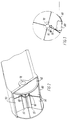
- Fig 2 shows the blade wheel and a guide plate 80 arranged behind the plate wheel in the housing 10 and along which objects picked up by the blade wheel are moved to the magazine in the housing 10 disposed behind the guide plate.
- the blade wheel in this case has four set of blades. It will be seen that in axial direction the blade wheel is divided into two blade sections, i.e. is divided in the center.
- the wheel set 40 also constitutes an integral part of the blade wheel through the shaft 70. Thus, the blade wheel is driven directly by the rotation of the wheel set 40.
- Each integral hinge 60 here extends in parallel with the shaft 70 of the blade wheel and is formed by a weakening in the blade 50.
- This weakening will usually be in the form of a thickness reduction, but may also be provided by punching portions of material along the line formed by the integral hinge, so that the two parts of the blade are connected by a plurality of bridges transversely to the integral hinge 60.
- a continuous reduction in thickness the integral hinge 60 tends to cause breaks (nick formation) at the ends of the blades, but this may be avoided by terminating the thickness reduction in a bead 55.
- a bead which connects the two parts of the blade divided by the integral hinge 60, effectively prevents such nick formation.
- a wheel 40 will usually only be contiguous with the blade wheel through the shaft 70, but it may be considered expedient in some cases that also the blade part positioned between the integral hinge 60 and the shaft 70 is contiguous with the inner side of the wheel.
- the guide plate 80 will usually follow the contour of the blade wheel, but this is not necessary if a sufficiently high speed is imparted to an object when contacting a blade 50, so that the object will be able to pass a guide plate 80 after having contacted the blade only once.
- the resilient properties of the individual blade 50 are determined by the length of the integral hinge 60, the shape of the integral hinge 60 as well as the selection of material.
- Fig. 3 schematically shows the hinge upon contact with a relatively large, box-shaped object 100. It will be seen that a blade 50 will bend about the integral hinge 60 when a box-shaped object 100 is present between the guide plate 80 and the blade 50. As indicated in broken line, the rotation of the blade wheel continues, which results in further bending of the blade 50 about the integral hinge 60. In case of sufficient friction between the object 100 and the contact area on the blade 50, the object 100, as shown in dotted line, will follow the movement of the blade 50 and be tilted about the contact point with the guide plate 80. The object 100 can hereby be moved up the guide plate 80 and into the magazine.
- the friction properties of the blade may be improved by providing the blade with friction increasing means in the contact area, e.g. in the form of a rubber coating 90, which appears from fig. 4.
- Fig 5. shows how the friction increasing means may be formed by grooves 75 in the axial direction of the blade wheel.
- FIG. 6 shows another solution to this problem where the blade 50, in the contact area with the large block 100, is formed with a flange 110 in the axial direction of the blade and perpendicularly to it. The object 100 will thereby be subjected to a force at a relatively high place so that the object 100 will tilt about the front edge of the guide plate 80 and up said plate.
- Fig. 7 shows an alternative embodiment where a blade wheel has a plurality of blades 50 with integral hinges in an axial direction.
- the blades 50 move the objects up a guide plate 80.
- the guide plate 80 is mounted to be resilient with pins 150 at each side which are adapted to run in guide tracks 140 in the walls of the housing 10.
- the housing 10 is formed with an eye 130 at the bottom, and a corresponding eye 131 is formed on the rear side of the guide plate 80, so that the guide plate 80 may be displaced along the track 140 under the action of a force from a spring 120 tensioned between the eyes 130 and 131.
- the guide plate 80 may thus be displaced from a position of rest in a direction substantially following the movement of the blade wheel under the action of a force increasing with the distance from the position of rest.
- the position of the integral hinge on a blade is determined by the size of the largest object which the blade wheel must be capable of picking up.
- the distance between the integral hinge and the tip of a blade must be so great that the largest object to be picked up must be capable of bending the blade about the integral hinge.
- the blade wheel is composed of two sections in an axial direction, but also this number depends upon the size of the objects to be picked up.
- the toy device of the invention will hereby be able to move large box-shaped objects into the magazine, so that the dynamic range of the toy device is increased considerably over the prior art.
- dynamic range is meant the difference between the largest and the smallest block which the device is able to pick up.
- the invention has been described in connection with a magazine inside the device, but nothing prevents the device from being formed with a platform to which the objects are moved.
Landscapes
- Toys (AREA)
- Vending Machines For Individual Products (AREA)
- Confectionery (AREA)
- Walking Sticks, Umbrellas, And Fans (AREA)
- Electrostatic Separation (AREA)
- Catching Or Destruction (AREA)
- Pens And Brushes (AREA)
Abstract
Description
- The invention concerns af toy device for picking up objects from a plane face, where a set of wheels drives rotary blades adapted to guide the objects into a magazine in the device.
- A plurality of examples of devices of the said type is known, which may in practice be divided into two different categories. The first category comprises i.a. a French application FR 7272/88, disclosing a unit for collecting tennis balls, which takes place by using plate-shaped blades. An American patent specification US 3,197,918 discloses a toy animal, which "eats" various objects which are moved into a magazine. A British patent GB 921,344 likewise provides an "eating" animal where objects or the "food" is moved into a magazine. An American patent specification US 3,983,662 provides a device for picking up objects such as toys. The device disclosed in said specification has a blade wheel with stiff blades coated with foamed plastics to cushion the forces which the stiff blades impart to the objects upon contact.
- It is common to the above-mentioned examples of prior art that all comprise blade wheels with stiff blades, entailing that these devices are only suitable for picking up round objects, since the blade wheel if hitting a box-shaped block will often drive up on the block instead of moving it into the magazine. Thus, these devices are not suitable for picking up building elements of a toy building set when these elements may be box-shaped. Further, the devices have the drawback that their dynamic range, i.e. the difference between the largest and the smallest object which may be picked up with the device, is rather limited.
- It has been attempted to compensate this in a plurality of other patent specifications belonging to the second category; an example of these is an American patent specification US 3,959,922 which provides a device for picking up objects, such as toys. The blade wheel is here made of a soft, spongy material. A German patent specification DE 873 669 describes how the toy may be picked up with a device having a brush mounted rotatably about a horizontal axis for moving the toy into a magazine. A toy car with a blade wheel having soft and relatively thick blades is described in a Danish patent specification DK 153 054. It is common to this second category of devices for picking up objects from a plane face that a horizontally positioned blade wheel with blades of soft, spongy or porous materials is provided at the front of the device. This has the drawback that the blades will rapidly be worn and destroyed. Further, materials of this type are difficult to clean, so that, in addition to the limited durability, also the difficult cleaning must be mentioned as one of the drawbacks.
- The object of the invention is to provide a toy device for picking up objects from a plane surface and moving them to a magazine, where the device must be capable of picking up objects having widely different sizes and shapes by means of a blade wheel, and the blades of the blade wheel must simultaneously be solid and so shaped that the device can pick up box-shaped blocks, also if a rotary blade wheel hits a block from above.
- This object is achieved according to the invention in that each blade comprises an integral hinge spaced from the axis of rotation of the blade wheel. As long as it does not encounter serious resistance from the objects to be picked up, a blade having such an integral hinge will operate like the stiff blade wheel according to the prior art, while the integral hinge will contribute with its effect when a blade is loaded substantially when contacting an object to be picked up.
- This load may be that a blade hits a box-shaped block from above. In the prior art, the vehicle would lift, but the integral hinge here entails that a blade will bend and move past the object which will then be guided to the magazine by the next blade.
- The invention is set out in claim 1. Advantageous embodiments of the invention are featured in the dependent claims 2 to 10.
- The integral hinge is preferably formed in parallel with the axis of rotation of the blade wheel, but in some cases, e.g. if the blade wheel is divided into two parts in an axial direction, it may be expedient to form the integral hinge so as to provide a reverse snow-plow effect, i.e. large objects are moved towards the center of the toy device when contacting the blades. Each blade may be provided with several spaced integral hinges in a radial direction so that the blade will be resilient. The integral hinge preferably consists in a longitudinal weakening which, to reinforce the hinge and counteract nick formation, is terminated in a bead at the ends of the blade, the bead forming a reinforced portion of material between the blade parts divided by the integral hinge.
- The blade wheel moves the objects into the magazine via a guide plate substantially following the curvature of the blade wheel. If a block is about to become jammed between a blade wheel and the lower part of this guide plate, the integral hinge entails that the object will be subjected to an upwardly directed force since the point of attack on the blade plate is brought closer to the axis of rotation of the blade wheel as the integral hinge is bent. This effect is increased if the blades, at least in the areas contacting objects, have friction increasing means. These means may be areas with grooves in the axial direction of the blade or may consist in a rubber coating on part of the blade.
- The guide plate may advantageously be mounted resiliently so that it may be displaced from a position of rest in a direction which substantially follows the movement of the blade wheel. This together with the operation of the integral hinge counteracts jamming of objects between the guide plate and the tip of a blade. For reasons of production, the driving wheel set often constitutes an integral part of the blade wheel and defines it at the sides.
- The invention will be explained more fully below with reference to the drawing, in which
- fig. 1 is a perspective view of a preferred embodiment of a toy device according to the invention,
- fig. 2 is a perspective view of the blade wheel and the guide plate in the device shown in fig. 1,
- fig. 3 is a schematic view of the operation of an integral hinge of a blade wheel,
- fig. 4 shows an alternative embodiment of the blades according to the invention,
- fig. 5 shows a third embodiment of a blade according to the invention,
- fig. 6 shows a fourth embodiment of a blade according to the invention, and
- fig. 7 is a schematic view of an embodiment with a resilient guide plate according to the invention.
- A toy device shown in fig. 1 comprises a
housing 10 which is box-shaped in the preferred embodiment and is adapted to be moved forward on a set ofwheels 40 at the front end of the housing and one or more slide knobs (not shown) at the rear end of the housing. Upwardly the housing has ahandle 20 with which a playing child can have a good grip in the toy device. Thehandle 20 extends like a bridge over a depression in the upper side of the housing. The rear end of the actual housing serves as a magazine for collected toys, which will be explained more fully below. Access to the magazine is ensured through aremovable door 30 engaging round its edge inwardly extending flanges on the walls of thehousing 10. Theplate 30 is retained in a closed position by a plurality ofknobs 31, so that theplate 30 may advantageously be made of an elastic material so that its resilient properties may be used for moving theplate 30 past theknobs 31. The rear wall of thehousing 10 upwardly has a centrally provided opening ordepression 32 by means of which a user can grip below theplate 30. When the objects to be picked up are formed by building elements from a toy building set, theplate 30 may advantageously be formed with coupling studs on the upper side so that the plate may be built together with these building elements. - At its front end the
housing 10 has a horizontally arranged blade wheel which may be rotated about ahorizontal shaft 70. The blade wheel has a plurality of radially protrudingblades 50. The blade wheel may advantageously be integral with the wheel set 40 and thus follows the rotation of the wheels. The preferred embodiment comprises precisely five sets ofblades 50 extending radially from theshaft 70. Each of these blades has an integral hinge formed at a distance from the axes of rotation of the blade wheel. Thewheels 40 may be formed with a rubber ring or arubber coating 41 on their rolling face so that the toy device has a better grip in the base. - Fig 2 shows the blade wheel and a
guide plate 80 arranged behind the plate wheel in thehousing 10 and along which objects picked up by the blade wheel are moved to the magazine in thehousing 10 disposed behind the guide plate. The blade wheel in this case has four set of blades. It will be seen that in axial direction the blade wheel is divided into two blade sections, i.e. is divided in the center. Thewheel set 40 also constitutes an integral part of the blade wheel through theshaft 70. Thus, the blade wheel is driven directly by the rotation of the wheel set 40. Eachintegral hinge 60 here extends in parallel with theshaft 70 of the blade wheel and is formed by a weakening in theblade 50. This weakening will usually be in the form of a thickness reduction, but may also be provided by punching portions of material along the line formed by the integral hinge, so that the two parts of the blade are connected by a plurality of bridges transversely to theintegral hinge 60. With a continuous reduction in thickness theintegral hinge 60, however, tends to cause breaks (nick formation) at the ends of the blades, but this may be avoided by terminating the thickness reduction in abead 55. Such a bead, which connects the two parts of the blade divided by theintegral hinge 60, effectively prevents such nick formation. - A
wheel 40 will usually only be contiguous with the blade wheel through theshaft 70, but it may be considered expedient in some cases that also the blade part positioned between theintegral hinge 60 and theshaft 70 is contiguous with the inner side of the wheel. Theguide plate 80 will usually follow the contour of the blade wheel, but this is not necessary if a sufficiently high speed is imparted to an object when contacting ablade 50, so that the object will be able to pass aguide plate 80 after having contacted the blade only once. - The resilient properties of the
individual blade 50 are determined by the length of theintegral hinge 60, the shape of theintegral hinge 60 as well as the selection of material. Fig. 3 schematically shows the hinge upon contact with a relatively large, box-shapedobject 100. It will be seen that ablade 50 will bend about theintegral hinge 60 when a box-shapedobject 100 is present between theguide plate 80 and theblade 50. As indicated in broken line, the rotation of the blade wheel continues, which results in further bending of theblade 50 about theintegral hinge 60. In case of sufficient friction between theobject 100 and the contact area on theblade 50, theobject 100, as shown in dotted line, will follow the movement of theblade 50 and be tilted about the contact point with theguide plate 80. Theobject 100 can hereby be moved up theguide plate 80 and into the magazine. - If the material of which the blade wheel is manufactured does not provide sufficient friction between the
object 100 and theblade 50, the friction properties of the blade may be improved by providing the blade with friction increasing means in the contact area, e.g. in the form of arubber coating 90, which appears from fig. 4. Fig 5. shows how the friction increasing means may be formed by grooves 75 in the axial direction of the blade wheel. - Small objects usually pose no problems when picked up to the magazine, since the blade wheel, because of the horizontal distance of the
shaft 70 from the front edge on theguide plate 80, will impart a substantially horizontal force to these small objects toward theguide plate 80 and up said plate. These small objects will therefore not be able to bend theindividual blades 50 about theintegral hinge 60, so the blade wheel will operate as if it just hadstiff blades 50. Large objects, which are e.g. larger than the horizontal distance between theshaft 70 and the front edge of theguide plate 80, will be caused to contact both theguide plate 80 and theblade 50 before theblade 50 reaches a vertical position, so that theobject 100 will be affected by a not insignificant force in a downward direction, and such anobject 100 will therefore with great probability be jammed between the guide plate and a blade according to the prior art. This may be obviated by providing theblade 50 withfriction coatings 90, 95, optionally with additional integral hinges so that greater bending may be achieved. Fig. 6 shows another solution to this problem where theblade 50, in the contact area with thelarge block 100, is formed with aflange 110 in the axial direction of the blade and perpendicularly to it. Theobject 100 will thereby be subjected to a force at a relatively high place so that theobject 100 will tilt about the front edge of theguide plate 80 and up said plate. - Fig. 7 shows an alternative embodiment where a blade wheel has a plurality of
blades 50 with integral hinges in an axial direction. Theblades 50 move the objects up aguide plate 80. To prevent theobject 100 from getting jammed between theblade 50 and theguide plate 80, theguide plate 80 is mounted to be resilient withpins 150 at each side which are adapted to run in guide tracks 140 in the walls of thehousing 10. Thehousing 10 is formed with aneye 130 at the bottom, and acorresponding eye 131 is formed on the rear side of theguide plate 80, so that theguide plate 80 may be displaced along thetrack 140 under the action of a force from aspring 120 tensioned between theeyes guide plate 80 may thus be displaced from a position of rest in a direction substantially following the movement of the blade wheel under the action of a force increasing with the distance from the position of rest. - The position of the integral hinge on a blade is determined by the size of the largest object which the blade wheel must be capable of picking up. The distance between the integral hinge and the tip of a blade must be so great that the largest object to be picked up must be capable of bending the blade about the integral hinge. In the preferred embodiment the blade wheel is composed of two sections in an axial direction, but also this number depends upon the size of the objects to be picked up.
- Since the
integral hinge 50 is spaced from the axis of rotation of the blade wheel, a blade when bent will apply a pull-force to an object in a direction toward the integral hinge. The toy device of the invention will hereby be able to move large box-shaped objects into the magazine, so that the dynamic range of the toy device is increased considerably over the prior art. By dynamic range is meant the difference between the largest and the smallest block which the device is able to pick up. - The invention has been described in connection with a magazine inside the device, but nothing prevents the device from being formed with a platform to which the objects are moved.
Claims (10)
- A toy device for picking up objects from a plane face, where a set of wheels (40) drives rotating blades (50) adapted to guide the objects into a magazine in the device, said blades consisting of a relatively stiff material, characterized in that each blade comprises an integral hinge (60) spaced from the axis of rotation of the blade wheel.
- A toy device according to claim 1, characterized in that the integral hinge (60) extends in parallel with the axis of rotation.
- A toy device according to claim 1 or 2, characterized in that each blade (50) has more than one integral hinge (60).
- A toy device according to claims 1-3, characterized in that a reinforcement in the form of a bead (55) between two of the plate-shaped parts of the blade is provided at least at one end of an integral hinge (60).
- A toy device according to claims 1-4, characterized in that the blades (50) have friction increasing means (90, 95) at least in the areas which are caused to contact the objects.
- A toy device according to claim 5, characterized in that the friction increasing means are areas with grooves (95) in the axial direction of the blade.
- A toy device according to claim 5, characterized in that the blades (50) are provided with a rubber coating (90) in the areas caused to contact the objects.
- A toy device according to claims 1-7, characterized in that a guide plate (80) is formed along the blade (50) and is constructed so that the guide plate (80) substantially follows the curvature of the blade wheel, whereby the blade wheel can move an object (100) up the guide plate (80) from the plane face towards the magazine.
- A device according to claims 1-8, characterized in that the guide plate (80) is mounted to be resilient so that it may be displaced from a position of rest in a direction substantially following the movement of the blade wheel under the action of a force increasing with the distance from the position of rest.
- A device according to claims 1-9, characterized in that the driving wheel set (40) constitutes an integral part of the blade wheel and defines it at the sides.
Applications Claiming Priority (3)
| Application Number | Priority Date | Filing Date | Title |
|---|---|---|---|
| DK2874/90 | 1990-12-04 | ||
| DK287490A DK167053B1 (en) | 1990-12-04 | 1990-12-04 | TOYS FITTING TO COLLECT ITEMS FROM A PLAN FLAD |
| PCT/DK1991/000372 WO1992010255A1 (en) | 1990-12-04 | 1991-12-03 | A toy device for picking up objects from a plane face |
Publications (2)
| Publication Number | Publication Date |
|---|---|
| EP0560846A1 EP0560846A1 (en) | 1993-09-22 |
| EP0560846B1 true EP0560846B1 (en) | 1995-03-01 |
Family
ID=8116677
Family Applications (1)
| Application Number | Title | Priority Date | Filing Date |
|---|---|---|---|
| EP92900336A Expired - Lifetime EP0560846B1 (en) | 1990-12-04 | 1991-12-03 | A toy device for picking up objects from a plane face |
Country Status (11)
| Country | Link |
|---|---|
| US (1) | US5378191A (en) |
| EP (1) | EP0560846B1 (en) |
| JP (1) | JPH06503239A (en) |
| AT (1) | ATE119053T1 (en) |
| AU (1) | AU650704B2 (en) |
| CA (1) | CA2097802C (en) |
| DE (1) | DE69107859T2 (en) |
| DK (2) | DK167053B1 (en) |
| ES (1) | ES2069408T3 (en) |
| HK (1) | HK1005433A1 (en) |
| WO (1) | WO1992010255A1 (en) |
Families Citing this family (21)
| Publication number | Priority date | Publication date | Assignee | Title |
|---|---|---|---|---|
| DK166861B1 (en) * | 1989-11-29 | 1993-07-26 | Lego As | SELECTABLE TOYS |
| US5474483A (en) * | 1995-01-13 | 1995-12-12 | Sun; Jin R. | Wheeled toy container with surface to attach blocks |
| US6068537A (en) * | 1995-11-06 | 2000-05-30 | Go Sport Ltd | Game apparatus and method |
| GB9716584D0 (en) * | 1997-08-05 | 1997-10-08 | Econ Engineering Ltd | Improvements in machinery for playing sports and games |
| US5947787A (en) * | 1997-09-24 | 1999-09-07 | Parvia Corporation | Modular lattice substructure for a toy building set |
| US6129605A (en) * | 1997-09-24 | 2000-10-10 | Parvia Corporation | Modular base units for a toy building set |
| US5951356A (en) * | 1997-10-27 | 1999-09-14 | Parvia Corporation | Modular lattice substructure for a toy building set having columns and foundations |
| US5924905A (en) * | 1997-09-24 | 1999-07-20 | Parvia Corporation | Modular terrain for a toy building set |
| US5993283A (en) * | 1997-09-30 | 1999-11-30 | Parvia Corporation | Modular buildings for a toy building set |
| US6007401A (en) * | 1997-10-03 | 1999-12-28 | Parvia Corporation | Optoelectric remote control apparatus for guiding toy vehicles |
| US6102770A (en) * | 1997-10-03 | 2000-08-15 | Parvia Corporation | Toy vehicular electromechanical guidance apparatus |
| US5865661A (en) * | 1997-10-03 | 1999-02-02 | Parvia Corporation | Toy vehicular drive apparatus |
| US6012957A (en) * | 1997-10-27 | 2000-01-11 | Parvia Corporation | Single beam optoelectric remote control apparatus for control of toys |
| DE50100574D1 (en) | 2001-01-26 | 2003-10-09 | Bruder Spielwaren Gmbh & Co Kg | Toy waste transportation vehicle |
| USD577080S1 (en) | 2007-11-02 | 2008-09-16 | Hasbro, Inc. | Ride on toy dump truck bed |
| USD624607S1 (en) | 2009-05-19 | 2010-09-28 | Hasbro, Inc. | Toy vehicle grill frame |
| US8858290B2 (en) * | 2012-05-21 | 2014-10-14 | Mattel, Inc. | Push toy with amusement features |
| US10265637B2 (en) * | 2017-03-14 | 2019-04-23 | Eliezer Leider | Ride-on and push toy for storage and picking up small objects on plane surface |
| CN112755545A (en) * | 2020-12-03 | 2021-05-07 | 浙江德威工艺品有限公司 | Auto-induction collection device of building blocks toy is exclusively used in |
| US20260001006A1 (en) * | 2024-06-26 | 2026-01-01 | Spin Master Ltd. | Carrier vehicle for collecting objects from a surface |
| US12397241B1 (en) * | 2025-03-25 | 2025-08-26 | Jiayang Huang | Children's car with cleaning function |
Family Cites Families (18)
| Publication number | Priority date | Publication date | Assignee | Title |
|---|---|---|---|---|
| US2287133A (en) * | 1940-12-31 | 1942-06-23 | Fastpic Corp | Toy |
| DE873669C (en) * | 1950-11-28 | 1953-04-16 | Adolf Buettner | Toy sweeper |
| US2940242A (en) * | 1957-01-22 | 1960-06-14 | James D Patterson | Nut and fruit harvester |
| US2960791A (en) * | 1959-05-21 | 1960-11-22 | Marvin I Glass | Toy |
| DE1281328B (en) * | 1961-02-25 | 1968-10-24 | Lehmann Ernst Paul | Movable, e.g. B. mobile toys in replica of an eating animal |
| US3197918A (en) * | 1962-02-20 | 1965-08-03 | Coggeshall Charles Henry | Animated wheeled eating toy |
| US3240201A (en) * | 1962-05-14 | 1966-03-15 | Harold L Shelton | Ball pick-up and projecting toy |
| US3308613A (en) * | 1964-03-10 | 1967-03-14 | Davidson Clarence Orden | Nut gathering apparatus |
| US3862538A (en) * | 1972-03-14 | 1975-01-28 | James A Henson | Nut harvesting machine |
| US3777462A (en) * | 1972-03-17 | 1973-12-11 | J Sharp | Fruit harvester |
| US3986324A (en) * | 1975-01-09 | 1976-10-19 | Billie Lee Harriott | Melon pickup and loading machine |
| US3959922A (en) * | 1975-05-16 | 1976-06-01 | Mattel, Inc. | Push toy adapted to pick up three-dimensional objects lying on a supporting surface |
| US3983662A (en) * | 1975-09-24 | 1976-10-05 | Mattel, Inc. | Push toy for picking up three-dimensional objects |
| US4031659A (en) * | 1975-11-10 | 1977-06-28 | Marvin Glass & Associates | Toy pick-up vehicle |
| CH662058A5 (en) * | 1984-01-18 | 1987-09-15 | Createchnic Dev Ag | Apparatus for the collection of tennis balls |
| FR2558380B1 (en) * | 1984-01-19 | 1986-06-13 | Bossard Maurice | APPARATUS FOR FACILITATING THE COLLECTION OF TENNIS AND GOLF BALLS |
| FR2631839A1 (en) * | 1988-05-27 | 1989-12-01 | Barsoumian Movses | Apparatus for picking up tennis balls |
| US4917648A (en) * | 1988-08-09 | 1990-04-17 | Hartje Robert A | Toy sanitation truck |
-
1990
- 1990-12-04 DK DK287490A patent/DK167053B1/en not_active IP Right Cessation
-
1991
- 1991-12-03 DE DE69107859T patent/DE69107859T2/en not_active Expired - Fee Related
- 1991-12-03 AU AU90377/91A patent/AU650704B2/en not_active Ceased
- 1991-12-03 HK HK98104595A patent/HK1005433A1/en not_active IP Right Cessation
- 1991-12-03 US US08/070,437 patent/US5378191A/en not_active Expired - Fee Related
- 1991-12-03 AT AT92900336T patent/ATE119053T1/en not_active IP Right Cessation
- 1991-12-03 ES ES92900336T patent/ES2069408T3/en not_active Expired - Lifetime
- 1991-12-03 EP EP92900336A patent/EP0560846B1/en not_active Expired - Lifetime
- 1991-12-03 CA CA002097802A patent/CA2097802C/en not_active Expired - Fee Related
- 1991-12-03 DK DK92900336.6T patent/DK0560846T3/en active
- 1991-12-03 WO PCT/DK1991/000372 patent/WO1992010255A1/en not_active Ceased
- 1991-12-03 JP JP4501129A patent/JPH06503239A/en active Pending
Also Published As
| Publication number | Publication date |
|---|---|
| CA2097802C (en) | 2000-02-08 |
| JPH06503239A (en) | 1994-04-14 |
| AU650704B2 (en) | 1994-06-30 |
| AU9037791A (en) | 1992-07-08 |
| EP0560846A1 (en) | 1993-09-22 |
| DE69107859D1 (en) | 1995-04-06 |
| US5378191A (en) | 1995-01-03 |
| DK0560846T3 (en) | 1995-05-29 |
| DK287490A (en) | 1992-06-05 |
| ES2069408T3 (en) | 1995-05-01 |
| DK287490D0 (en) | 1990-12-04 |
| DK167053B1 (en) | 1993-08-23 |
| DE69107859T2 (en) | 1995-11-09 |
| CA2097802A1 (en) | 1992-06-05 |
| HK1005433A1 (en) | 1999-01-08 |
| ATE119053T1 (en) | 1995-03-15 |
| WO1992010255A1 (en) | 1992-06-25 |
Similar Documents
| Publication | Publication Date | Title |
|---|---|---|
| US5378191A (en) | Toy device for picking up objects from a plane face | |
| HK1005433B (en) | A toy device for picking up objects from a plane face | |
| CN1923109B (en) | Automatically displaceable floor-type dust collector | |
| CN114233063A (en) | Swimming pool cleaning robot and steering method | |
| EP2578282B1 (en) | Autonomous vehicle system | |
| US4535992A (en) | Training device for putting golf balls | |
| EP0265205B1 (en) | Floor cleaner | |
| US20190201803A1 (en) | Ride-on and push toy for storage and picking up small objects on plane surface | |
| US5013367A (en) | Rug cleaning apparatus | |
| US20130084774A1 (en) | Autonomous vehicle system | |
| JP2537613B2 (en) | Ball game equipment for ball game machines | |
| AU672875B2 (en) | Gliding object as recreational sporting goods | |
| EP0826401A3 (en) | Toy game | |
| EP1871495A1 (en) | A method and apparatus for throwing and catching | |
| WO2013052140A2 (en) | Autonomous vehicle system | |
| EP0054552A1 (en) | Competition game machine | |
| CN112493929A (en) | Ground cleaning mechanism and sweeper | |
| CA1140177A (en) | Competitive game moving objects through adjacent depressions in an inclined surface | |
| US3767200A (en) | Shuffleboard type of game with steps and sliding gamepieces | |
| US4223889A (en) | Bumper structure including drive mechanism | |
| CN114379962A (en) | Garbage classification delivery system based on big data | |
| CN114906576A (en) | Belt cleaner and using method thereof | |
| JPH07102628A (en) | Noise suppression mechanism of automatic dust remover | |
| GB2041766A (en) | A magnetic ice-hockey game | |
| JPH07155476A (en) | Top toys and game boards |
Legal Events
| Date | Code | Title | Description |
|---|---|---|---|
| PUAI | Public reference made under article 153(3) epc to a published international application that has entered the european phase |
Free format text: ORIGINAL CODE: 0009012 |
|
| 17P | Request for examination filed |
Effective date: 19930525 |
|
| AK | Designated contracting states |
Kind code of ref document: A1 Designated state(s): AT BE CH DE DK ES FR GB GR IT LI LU MC NL SE |
|
| 17Q | First examination report despatched |
Effective date: 19940429 |
|
| RAP1 | Party data changed (applicant data changed or rights of an application transferred) |
Owner name: INTERLEGO AG Owner name: LEGO A/S |
|
| GRAA | (expected) grant |
Free format text: ORIGINAL CODE: 0009210 |
|
| ITF | It: translation for a ep patent filed | ||
| AK | Designated contracting states |
Kind code of ref document: B1 Designated state(s): AT BE CH DE DK ES FR GB GR IT LI LU MC NL SE |
|
| PG25 | Lapsed in a contracting state [announced via postgrant information from national office to epo] |
Ref country code: NL Free format text: LAPSE BECAUSE OF NON-PAYMENT OF DUE FEES Effective date: 19950301 Ref country code: MC Free format text: LAPSE BECAUSE OF NON-PAYMENT OF DUE FEES Effective date: 19950301 Ref country code: LI Effective date: 19950301 Ref country code: GR Free format text: LAPSE BECAUSE OF FAILURE TO SUBMIT A TRANSLATION OF THE DESCRIPTION OR TO PAY THE FEE WITHIN THE PRESCRIBED TIME-LIMIT Effective date: 19950301 Ref country code: FR Effective date: 19950301 Ref country code: CH Effective date: 19950301 Ref country code: BE Effective date: 19950301 Ref country code: AT Effective date: 19950301 |
|
| REF | Corresponds to: |
Ref document number: 119053 Country of ref document: AT Date of ref document: 19950315 Kind code of ref document: T |
|
| REF | Corresponds to: |
Ref document number: 69107859 Country of ref document: DE Date of ref document: 19950406 |
|
| REG | Reference to a national code |
Ref country code: ES Ref legal event code: FG2A Ref document number: 2069408 Country of ref document: ES Kind code of ref document: T3 |
|
| REG | Reference to a national code |
Ref country code: DK Ref legal event code: T3 |
|
| PG25 | Lapsed in a contracting state [announced via postgrant information from national office to epo] |
Ref country code: SE Effective date: 19950601 |
|
| REG | Reference to a national code |
Ref country code: CH Ref legal event code: PL |
|
| EN | Fr: translation not filed | ||
| NLV1 | Nl: lapsed or annulled due to failure to fulfill the requirements of art. 29p and 29m of the patents act | ||
| PG25 | Lapsed in a contracting state [announced via postgrant information from national office to epo] |
Ref country code: LU Free format text: LAPSE BECAUSE OF NON-PAYMENT OF DUE FEES Effective date: 19951231 |
|
| PLBE | No opposition filed within time limit |
Free format text: ORIGINAL CODE: 0009261 |
|
| STAA | Information on the status of an ep patent application or granted ep patent |
Free format text: STATUS: NO OPPOSITION FILED WITHIN TIME LIMIT |
|
| 26N | No opposition filed | ||
| PGFP | Annual fee paid to national office [announced via postgrant information from national office to epo] |
Ref country code: GB Payment date: 19991201 Year of fee payment: 9 |
|
| PGFP | Annual fee paid to national office [announced via postgrant information from national office to epo] |
Ref country code: DK Payment date: 19991202 Year of fee payment: 9 |
|
| PGFP | Annual fee paid to national office [announced via postgrant information from national office to epo] |
Ref country code: ES Payment date: 19991215 Year of fee payment: 9 Ref country code: DE Payment date: 19991215 Year of fee payment: 9 |
|
| PG25 | Lapsed in a contracting state [announced via postgrant information from national office to epo] |
Ref country code: GB Free format text: LAPSE BECAUSE OF NON-PAYMENT OF DUE FEES Effective date: 20001203 Ref country code: DK Free format text: LAPSE BECAUSE OF NON-PAYMENT OF DUE FEES Effective date: 20001203 |
|
| GBPC | Gb: european patent ceased through non-payment of renewal fee |
Effective date: 20001203 |
|
| REG | Reference to a national code |
Ref country code: DK Ref legal event code: EBP |
|
| PG25 | Lapsed in a contracting state [announced via postgrant information from national office to epo] |
Ref country code: DE Free format text: LAPSE BECAUSE OF NON-PAYMENT OF DUE FEES Effective date: 20011002 |
|
| PG25 | Lapsed in a contracting state [announced via postgrant information from national office to epo] |
Ref country code: ES Free format text: LAPSE BECAUSE OF NON-PAYMENT OF DUE FEES Effective date: 20011204 |
|
| REG | Reference to a national code |
Ref country code: ES Ref legal event code: FD2A Effective date: 20020112 |
|
| PG25 | Lapsed in a contracting state [announced via postgrant information from national office to epo] |
Ref country code: IT Free format text: LAPSE BECAUSE OF NON-PAYMENT OF DUE FEES Effective date: 20051203 |