EP0560820B1 - Method and device for cleaning fan impellers - Google Patents
Method and device for cleaning fan impellers Download PDFInfo
- Publication number
- EP0560820B1 EP0560820B1 EP91920700A EP91920700A EP0560820B1 EP 0560820 B1 EP0560820 B1 EP 0560820B1 EP 91920700 A EP91920700 A EP 91920700A EP 91920700 A EP91920700 A EP 91920700A EP 0560820 B1 EP0560820 B1 EP 0560820B1
- Authority
- EP
- European Patent Office
- Prior art keywords
- outlet cylinder
- impeller
- compressed air
- solid material
- cannon
- Prior art date
- Legal status (The legal status is an assumption and is not a legal conclusion. Google has not performed a legal analysis and makes no representation as to the accuracy of the status listed.)
- Expired - Lifetime
Links
Images

Classifications
-
- F—MECHANICAL ENGINEERING; LIGHTING; HEATING; WEAPONS; BLASTING
- F04—POSITIVE - DISPLACEMENT MACHINES FOR LIQUIDS; PUMPS FOR LIQUIDS OR ELASTIC FLUIDS
- F04D—NON-POSITIVE-DISPLACEMENT PUMPS
- F04D29/00—Details, component parts, or accessories
- F04D29/70—Suction grids; Strainers; Dust separation; Cleaning
- F04D29/701—Suction grids; Strainers; Dust separation; Cleaning especially adapted for elastic fluid pumps
- F04D29/703—Suction grids; Strainers; Dust separation; Cleaning especially adapted for elastic fluid pumps specially for fans, e.g. fan guards
Definitions
- the present invention relates to a method and a device for cleaning fan impellers, said device comprising at least one compressed air cannon for directing shots in the form of pulses of compressed air towards the impeller blades or other parts of the impeller, subjected to deposits.
- FIG. 1 shows an example of a device according to this prior art with a compressed air cannon disposed at the fan inlet.
- the hardness of the deposits on the blade surfaces will be so high that the deposits can not be efficiently removed by pulses of compressed air.
- the purpose of the present invention is to improve the efficiency of removing such hard deposits from impeller blades or other parts of a fan impeller.
- hard deposits are removed by throwing bursts of solid material towards the impeller blades or other parts of the impeller, subjected to deposits.
- the bursts of solid material are thrown periodically or are controlled as a function of the level of vibration of impeller bearings.
- the bursts of solid material are thrown towards diametrically opposite blades of the impeller by means of two compressed air cannons to avoid excessive unbalance due to unsticking of the deposits.
- the instant of shooting bursts of solid material is controlled as a function of the blade positions of the rotating impeller to provoke unsticking of deposits on the different blades in a selected order to reduce the unbalance created by this removal of deposits.
- the solid material is contained in a cylindrical cartridge, intended to be positioned in the outlet cylinder of the cannon, the ends of the cylindrical cartridge being closed by a material, brittle enough to be broken by the compressed air pulse.
- the cartridge has to be of sufficient strength to keep the material during transportation, while the ends of the cartridge has to be so brittle that it is broken, when used in the air cannon, by the shot of compressed air from the cannon.
- the solid material used is chosen according to the hardness of the deposits and the fans liability to damages.
- the chosen solid material must be of sufficient strength to crush the deposits and at the same time be friable enough to eliminate the risk of damage or wearing of the impeller blades or other parts of the impeller.
- the solid material is formed of a coarse-grained material, the size of the grains being preferably between 5 and 50 mm, which coarse-grain material is friable without hard contents, and is preferably formed of gypsum stones.
- the solid material can also comprise an explosive which will explode when hitting the impeller blades or other parts of the impeller, subjected to deposits. With such a material a still more efficient cleaning effect can be obtained.
- Fig. 1 shows a fan comprising an impeller 10 mounted inside a fan casing or fan scroll 18.
- a compressed air cannon 26 is located at the impeller inlet.
- the outlet cylinder 28 of the cannon 26 can be oriented in the axial direction of the fan or in any inclined direction to deliver compressed air pulses towards the impeller blades 24.
- the compressed air cannon which can be of the type described in the Swedish Patent Application 8902335-2 is shown in Fig. 1 in two different orientations by solid lines and dashed lines, respectively.
- FIG. 2-4 A portion of the outlet cylinder 28 is shown in Fig. 2-4.
- a cartridge 2 containing solid material 4 is placed in the bore of the outlet cylinder 28.
- the cartridge 2 is formed of a material of sufficient strength to keep the material during transportation without damages.
- the ends of the cylinder are closed by a material 3 which is broken by the pressure pulse from the air cannon 26, such that the material 4 is thrown through the outlet cylinder 28 to hit the impeller blades 24 or possibly other parts of the impeller subjected to deposits.
- the end walls 3 of the cartridge 2 can be formed e.g. of an expanded polystyrene composit or formed as cover plates of a thickness of up to 2 cm which plates are stuck with a proper adhesive to the cartridge cylinder.
- the end walls 3 could be formed of paper of suitable quality.
- the outlet cylinder 28 comprises a removable portion 5 in the form of a half cylinder in which a retainer cylinder 6 for the cartridge 2 is mounted.
- the half cylinder 5 is articuledly mounted by a hinge 30 to the remaining part of the outlet cylinder 28, such that the half cylinder 5 can be swung along the hinge axis 8 out of the bore of the outlet cylinder 28.
- the retainer cylinder 6 mounted in the half cylinder 5 can be removed from the bore of the outlet cylinder to allow removal of used cartridges 2 and insertion of new ones containing the solid material 4, whereupon the new cartridge 2 is swung into the bore of the outlet cylinder 28.
- a suitable clamping device 32 As a closing device for the movable half cylinder 5 a suitable clamping device 32 is used. A sealing 7 is disposed between flanges 34 and 36 formed on the half cylinder 5 and the outlet cylinder 28 respectively to avoid air leakage with the half cylinder 5 positioned in the bore of the outlet cylinder 28.
- a construction with guide bars can be used to allow removal of the removable portion from the outlet cylinder by a translational motion, or a revolver system can be associated with the outlet cylinder to allow loading of several cartridges.
- the opening of the outlet cylinder to remove used cartridges and inserting new ones is not dangerous for the operator, even if the fan is operating with hot gases.
- the fan is operating at a pressure below atmospheric pressure, and therefore when opening the outlet cylinder air is flowing from the atmosphere into the fan.
- the removable part of the outlet cylinder is then cleaned from dust and cooled rapidly.
- the solid material 4 is a rather friable, coarse-grained material with a typical grain size of 5 to 50 mm.
- the material is selected depending on the application such that deposits are effectively crushed and then blown away as a powder while the material is friable enough for eliminatig any risk of damage or wearing of the impeller blades.
- gypsum stones can be used without any hard content that could give rise to wear.
- the solid material can also be formed of an explosive which will explode when hitting the impeller blades or other parts of the impeller subjected to deposits.
Landscapes
- Engineering & Computer Science (AREA)
- Mechanical Engineering (AREA)
- General Engineering & Computer Science (AREA)
- Structures Of Non-Positive Displacement Pumps (AREA)
- Cleaning In General (AREA)
- Ventilation (AREA)
- Disintegrating Or Milling (AREA)
Abstract
Description
- The present invention relates to a method and a device for cleaning fan impellers, said device comprising at least one compressed air cannon for directing shots in the form of pulses of compressed air towards the impeller blades or other parts of the impeller, subjected to deposits.
- In Swedish Patent Application No. 8902335-2 (WO 91/00430) a method and a device is described for producing a shock wave by means of a compressed air cannon to unstick deposits on fan impeller blades. This technique is applicable to fans used under heavy environment conditions, like in dusty spaces such as in kilns of cement plants where deposits of dust on the impellers can cause severe vibration problems. Figure 1 shows an example of a device according to this prior art with a compressed air cannon disposed at the fan inlet.
- In some applications the hardness of the deposits on the blade surfaces will be so high that the deposits can not be efficiently removed by pulses of compressed air.
- The purpose of the present invention is to improve the efficiency of removing such hard deposits from impeller blades or other parts of a fan impeller.
- This purpose is obtained by a method according to claim 1 and a device according to
claim 6. - According to the invention hard deposits are removed by throwing bursts of solid material towards the impeller blades or other parts of the impeller, subjected to deposits.
- According to advantageous embodiments of the method according to the invention the bursts of solid material are thrown periodically or are controlled as a function of the level of vibration of impeller bearings.
- According to another advantageous embodiment of the method according to the invention the bursts of solid material are thrown towards diametrically opposite blades of the impeller by means of two compressed air cannons to avoid excessive unbalance due to unsticking of the deposits.
- According to still another advantageous embodiment of the method according to the invention the instant of shooting bursts of solid material is controlled as a function of the blade positions of the rotating impeller to provoke unsticking of deposits on the different blades in a selected order to reduce the unbalance created by this removal of deposits.
- According to an advantageous embodiment of the device according to the invention the solid material is contained in a cylindrical cartridge, intended to be positioned in the outlet cylinder of the cannon, the ends of the cylindrical cartridge being closed by a material, brittle enough to be broken by the compressed air pulse. Thus the cartridge has to be of sufficient strength to keep the material during transportation, while the ends of the cartridge has to be so brittle that it is broken, when used in the air cannon, by the shot of compressed air from the cannon.
- The solid material used is chosen according to the hardness of the deposits and the fans liability to damages. The chosen solid material must be of sufficient strength to crush the deposits and at the same time be friable enough to eliminate the risk of damage or wearing of the impeller blades or other parts of the impeller. Thus, according to still another advantageous embodiment of the device according to the invention the solid material is formed of a coarse-grained material, the size of the grains being preferably between 5 and 50 mm, which coarse-grain material is friable without hard contents, and is preferably formed of gypsum stones.
- The solid material can also comprise an explosive which will explode when hitting the impeller blades or other parts of the impeller, subjected to deposits. With such a material a still more efficient cleaning effect can be obtained.
- An exemplifying embodiment of the device according to the invention will now be described more in detail with reference to the enclosed drawings on which
- Fig. 1 shows an embodiment of a device of the type used in the present invention with a movable compressed air cannon located at the impeller inlet,
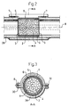
- Fig. 2 in an axial section a portion of the outlet cylinder of the air cannon charged with a cartridge containing solid material,
- Fig. 3 a cross-section through the plane A-A in fig. 2, and
- Fig. 4 a perspective view of the outlet cylinder of the air cannon with the retainer cylinder for the cartridge partly swung out.
- Fig. 1 shows a fan comprising an
impeller 10 mounted inside a fan casing orfan scroll 18. - A
compressed air cannon 26 is located at the impeller inlet. Theoutlet cylinder 28 of thecannon 26 can be oriented in the axial direction of the fan or in any inclined direction to deliver compressed air pulses towards theimpeller blades 24. The compressed air cannon which can be of the type described in the Swedish Patent Application 8902335-2 is shown in Fig. 1 in two different orientations by solid lines and dashed lines, respectively. - A portion of the
outlet cylinder 28 is shown in Fig. 2-4. Acartridge 2 containingsolid material 4 is placed in the bore of theoutlet cylinder 28. - The
cartridge 2 is formed of a material of sufficient strength to keep the material during transportation without damages. The ends of the cylinder are closed by amaterial 3 which is broken by the pressure pulse from theair cannon 26, such that thematerial 4 is thrown through theoutlet cylinder 28 to hit theimpeller blades 24 or possibly other parts of the impeller subjected to deposits. Theend walls 3 of thecartridge 2 can be formed e.g. of an expanded polystyrene composit or formed as cover plates of a thickness of up to 2 cm which plates are stuck with a proper adhesive to the cartridge cylinder. As another exemple theend walls 3 could be formed of paper of suitable quality. - The
outlet cylinder 28 comprises aremovable portion 5 in the form of a half cylinder in which aretainer cylinder 6 for thecartridge 2 is mounted. Thehalf cylinder 5 is articuledly mounted by ahinge 30 to the remaining part of theoutlet cylinder 28, such that thehalf cylinder 5 can be swung along thehinge axis 8 out of the bore of theoutlet cylinder 28. In this way theretainer cylinder 6 mounted in thehalf cylinder 5 can be removed from the bore of the outlet cylinder to allow removal of usedcartridges 2 and insertion of new ones containing thesolid material 4, whereupon thenew cartridge 2 is swung into the bore of theoutlet cylinder 28. - As a closing device for the movable half cylinder 5 a
suitable clamping device 32 is used. Asealing 7 is disposed betweenflanges half cylinder 5 and theoutlet cylinder 28 respectively to avoid air leakage with thehalf cylinder 5 positioned in the bore of theoutlet cylinder 28. - Other embodiments are possible for introducing the cartridges containing the solid material into the bore of the outlet cylinder. Thus e.g. a construction with guide bars can be used to allow removal of the removable portion from the outlet cylinder by a translational motion, or a revolver system can be associated with the outlet cylinder to allow loading of several cartridges.
- The opening of the outlet cylinder to remove used cartridges and inserting new ones is not dangerous for the operator, even if the fan is operating with hot gases. For such applications the fan is operating at a pressure below atmospheric pressure, and therefore when opening the outlet cylinder air is flowing from the atmosphere into the fan. As a consequence the removable part of the outlet cylinder is then cleaned from dust and cooled rapidly.
- The
solid material 4 is a rather friable, coarse-grained material with a typical grain size of 5 to 50 mm. The material is selected depending on the application such that deposits are effectively crushed and then blown away as a powder while the material is friable enough for eliminatig any risk of damage or wearing of the impeller blades. As an exemple gypsum stones can be used without any hard content that could give rise to wear. - The solid material can also be formed of an explosive which will explode when hitting the impeller blades or other parts of the impeller subjected to deposits.
Claims (10)
- A device for cleaning fan impellers (10), comprising at least one compressed air cannon (26) for directing shots in the form of pulses of compressed air towards the impeller blades (24) or other parts of the impeller, subjected to deposits, characterized in that the outlet cylinder (28) of the cannon (26) is loaded with a charge of solid material (4) to be thrown towards the impeller blades (24) or said other parts of the impeller subjected to deposits, when shooting a pulse of compressed air, the solid material (4) being contained in a cylindrical cartridge (2), intended to be positioned in the outlet cylinder (28) of the cannon, the ends of the cylindrical cartridge being closed by a material (3) brittle enough to be broken by the compressed air pulse.
- The device according to claim 1, characterized in that the material (3) closing the ends of the cylindrical cartridge (2) is formed of an expanded polystyrene composit.
- The device according to claims 1 or 2, characterized in that the ends of the cylindrical cartridge (2) are covered by plates stuck to the cartridge cylinder.
- The device according to any of the claims 1 through 3, characterized in that the outlet cylinder (28) of the air cannon (26) comprises a removable portion (5) for allowing insertion of the cartridge (2) containing the solid material (4) into the outlet cylinder of the air cannon.
- The device according to claim 4, characterized in that the removable portion (5) of the outlet cylinder (28) is mounted to the remaining part of the outlet cylinder by a hinge (30) allowing said removable portion to be swung out of the bore of the outlet cylinder along an axis (8) parallel to the axis of the outlet cylinder.
- The device according to claim 4, characterized in that a construction of guide bars is provided to allow removal of the removable portion out of the bore of the outlet cylinder by a translational motion.
- The device according to any of the claims 1 through 3, characterized in that a revolver system is coupled to the outlet cylinder (28) of the compressed air cannon (26) to allow loading of several cartridges (2) containing solid material (4).
- The device according to any of the claims 1 through 7, characterized in that the solid material (4) is formed of a coarse-grained material, the size of the grains being preferably between 5 and 50 mm.
- The device according to claim 8, characterized in that the coarse-grained material is friable and without hard contents, and preferably formed of gypsum stones.
- The device according to any of the claims 1 through 9, characterized in that the solid material (4) is an explosive which will explode when hitting the impeller blades (24) or said other parts of the impeller (10).
Applications Claiming Priority (3)
| Application Number | Priority Date | Filing Date | Title |
|---|---|---|---|
| SE9003907 | 1990-12-07 | ||
| SE9003907A SE468134B (en) | 1990-12-07 | 1990-12-07 | CLEANING DEVICE FOR A FLASH WHEEL, INCLUDING AATMINSTONE AND A PRESSURE AIR CANNON TO AIM SHOT IN THE FORM OF PRESSURE AIR PULSES TO THE FLASH WHEEL |
| PCT/SE1991/000820 WO1992010683A1 (en) | 1990-12-07 | 1991-12-03 | Method and device for cleaning fan impellers |
Publications (2)
| Publication Number | Publication Date |
|---|---|
| EP0560820A1 EP0560820A1 (en) | 1993-09-22 |
| EP0560820B1 true EP0560820B1 (en) | 1995-08-23 |
Family
ID=20381126
Family Applications (1)
| Application Number | Title | Priority Date | Filing Date |
|---|---|---|---|
| EP91920700A Expired - Lifetime EP0560820B1 (en) | 1990-12-07 | 1991-12-03 | Method and device for cleaning fan impellers |
Country Status (13)
| Country | Link |
|---|---|
| US (1) | US5427565A (en) |
| EP (1) | EP0560820B1 (en) |
| JP (1) | JP2915140B2 (en) |
| KR (1) | KR0184692B1 (en) |
| AU (1) | AU656748B2 (en) |
| CA (1) | CA2096337C (en) |
| DE (1) | DE69112424T2 (en) |
| DK (1) | DK0560820T3 (en) |
| ES (1) | ES2079080T3 (en) |
| FI (1) | FI102105B (en) |
| RU (1) | RU2076249C1 (en) |
| SE (1) | SE468134B (en) |
| WO (1) | WO1992010683A1 (en) |
Families Citing this family (8)
| Publication number | Priority date | Publication date | Assignee | Title |
|---|---|---|---|---|
| CA2101586A1 (en) * | 1992-08-05 | 1994-02-06 | Rajender Kamboj | Ampa-binding human glur4 receptors |
| DE20305604U1 (en) | 2003-04-07 | 2003-06-05 | Werner Rietschle GmbH + Co. KG, 79650 Schopfheim | Side channel fan has at least one compressed air nozzle is orientated against blades of impeller and installed in casing cover or in casing of fan |
| ITBO20040047A1 (en) * | 2004-02-03 | 2004-05-03 | Spal Srl | AXIAL FAN |
| US7409794B2 (en) * | 2004-09-20 | 2008-08-12 | Daniel Triano | Fishing line casting and bait projectile system |
| FR2893095B1 (en) * | 2005-11-10 | 2008-01-04 | Aldes Aeraulique Sa | MECHANICAL VENTILATION GROUP COMPRISING MEANS FOR CLEANING THE TURBINE BLADES BY COMPRESSED AIR INSUFFLATION |
| DE102006018384A1 (en) | 2006-04-20 | 2007-10-25 | Linde Ag | Method and device for defrosting and cleaning fans |
| RU2431062C1 (en) * | 2010-03-15 | 2011-10-10 | Открытое акционерное общество "Ракетно-космическая корпорация "Энергия" имени С.П. Королева" | Axial fan |
| CN115597111B (en) * | 2022-09-05 | 2024-08-20 | 珠海格力电器股份有限公司 | Cleaning device for air conditioner, cleaning method for air conditioner and air conditioner |
Family Cites Families (9)
| Publication number | Priority date | Publication date | Assignee | Title |
|---|---|---|---|---|
| US2807442A (en) * | 1952-01-29 | 1957-09-24 | Exxon Research Engineering Co | Momentum pellet impact drilling apparatus |
| US2972502A (en) * | 1953-08-25 | 1961-02-21 | Diamond Power Speciality | Projection-type cleaning apparatus |
| US3854997A (en) * | 1970-12-14 | 1974-12-17 | Peck Co C | Jet flame cleaning |
| ZA745833B (en) * | 1973-10-10 | 1975-10-29 | Polysius Ag | Device for cleaning fan blades |
| US4624689A (en) * | 1982-02-04 | 1986-11-25 | Mike Volk Co., Inc. | Pneumatic shock wave generator for cleaning filter cartridges |
| DE3324710C1 (en) * | 1983-07-08 | 1984-05-30 | Jost Dipl.-Ing. 2150 Buxtehude Wadephul | Device for accelerating blasting media |
| US4699665A (en) * | 1984-12-26 | 1987-10-13 | Anco Engineers, Inc. | Method of pressure pulse cleaning heat exchanger tubes, upper tube support plates and other areas in a nuclear steam generator and other tube bundle heat exchangers |
| SE8902335L (en) * | 1989-06-28 | 1990-12-29 | Flaekt Ab | PROCEDURE AND DEVICE FOR CLEANING WHEELS |
| US5303510A (en) * | 1990-05-11 | 1994-04-19 | The United States Of America As Represented By The United States Department Of Energy | Automatic feed system for ultrasonic machining |
-
1990
- 1990-12-07 SE SE9003907A patent/SE468134B/en not_active IP Right Cessation
-
1991
- 1991-12-03 EP EP91920700A patent/EP0560820B1/en not_active Expired - Lifetime
- 1991-12-03 AU AU89304/91A patent/AU656748B2/en not_active Ceased
- 1991-12-03 DK DK91920700.1T patent/DK0560820T3/en active
- 1991-12-03 ES ES91920700T patent/ES2079080T3/en not_active Expired - Lifetime
- 1991-12-03 DE DE69112424T patent/DE69112424T2/en not_active Expired - Fee Related
- 1991-12-03 RU RU9193045026A patent/RU2076249C1/en active
- 1991-12-03 KR KR1019930701672A patent/KR0184692B1/en not_active Expired - Fee Related
- 1991-12-03 CA CA002096337A patent/CA2096337C/en not_active Expired - Fee Related
- 1991-12-03 US US08/066,164 patent/US5427565A/en not_active Expired - Lifetime
- 1991-12-03 JP JP4500119A patent/JP2915140B2/en not_active Expired - Lifetime
- 1991-12-03 WO PCT/SE1991/000820 patent/WO1992010683A1/en not_active Ceased
-
1993
- 1993-06-04 FI FI932574A patent/FI102105B/en active
Also Published As
| Publication number | Publication date |
|---|---|
| FI102105B1 (en) | 1998-10-15 |
| DK0560820T3 (en) | 1995-11-13 |
| SE468134B (en) | 1992-11-09 |
| WO1992010683A1 (en) | 1992-06-25 |
| AU8930491A (en) | 1992-07-08 |
| US5427565A (en) | 1995-06-27 |
| FI932574A0 (en) | 1993-06-04 |
| JP2915140B2 (en) | 1999-07-05 |
| SE9003907L (en) | 1992-06-08 |
| JPH06505068A (en) | 1994-06-09 |
| DE69112424T2 (en) | 1996-02-29 |
| AU656748B2 (en) | 1995-02-16 |
| KR0184692B1 (en) | 1999-05-01 |
| CA2096337A1 (en) | 1992-06-08 |
| EP0560820A1 (en) | 1993-09-22 |
| RU2076249C1 (en) | 1997-03-27 |
| SE9003907D0 (en) | 1990-12-07 |
| DE69112424D1 (en) | 1995-09-28 |
| FI102105B (en) | 1998-10-15 |
| ES2079080T3 (en) | 1996-01-01 |
| CA2096337C (en) | 2004-04-20 |
| FI932574L (en) | 1993-06-04 |
Similar Documents
| Publication | Publication Date | Title |
|---|---|---|
| US5427565A (en) | Method and device for cleaning fan impellers | |
| US5025632A (en) | Method and apparatus for cryogenic removal of solid materials | |
| EP3053731B1 (en) | Methods of manufacturing and cleaning | |
| US5307743A (en) | Apparatus for deslagging a cyclone furnace | |
| EP0194121A1 (en) | Blast cleaning | |
| EP3808504A1 (en) | Impeller device for shot peening machine and shot peening machine | |
| US9146083B2 (en) | Projectile containment system | |
| US20210078137A1 (en) | Shot blasting machine and impeller assembly thereof | |
| US3704552A (en) | Spark plug cleaning devices | |
| US20070137539A1 (en) | Method for the removal of deposits on the internal walls of industrial furnaces of bunkers | |
| WO1991000430A1 (en) | Method and device for cleaning fan impellers | |
| CN108883516B (en) | Shot peening device | |
| RU93045026A (en) | THE DEVICE FOR CLEANING THE FAN VALVES | |
| JP2006103901A (en) | Rotary valve | |
| US4883406A (en) | Transport ventilator | |
| JP2006142422A (en) | Shot blast device | |
| CN220762259U (en) | Portable shot blasting machine | |
| CN219335221U (en) | Dry ice high-pressure spraying device | |
| SU876154A1 (en) | Device for grinding calcium carbide | |
| DE9422372U1 (en) | Deburring machine | |
| SU1021466A1 (en) | Hammer mill | |
| SU1060897A1 (en) | Plant for drying loose materials | |
| SU994365A1 (en) | Loose material slinger | |
| JPH0536082B2 (en) | ||
| SU1710319A1 (en) | Shot-blast cleaning apparatus |
Legal Events
| Date | Code | Title | Description |
|---|---|---|---|
| PUAI | Public reference made under article 153(3) epc to a published international application that has entered the european phase |
Free format text: ORIGINAL CODE: 0009012 |
|
| 17P | Request for examination filed |
Effective date: 19930602 |
|
| AK | Designated contracting states |
Kind code of ref document: A1 Designated state(s): DE DK ES FR GB IT |
|
| 17Q | First examination report despatched |
Effective date: 19941209 |
|
| GRAA | (expected) grant |
Free format text: ORIGINAL CODE: 0009210 |
|
| AK | Designated contracting states |
Kind code of ref document: B1 Designated state(s): DE DK ES FR GB IT |
|
| REF | Corresponds to: |
Ref document number: 69112424 Country of ref document: DE Date of ref document: 19950928 |
|
| REG | Reference to a national code |
Ref country code: DK Ref legal event code: T3 |
|
| ITF | It: translation for a ep patent filed | ||
| ET | Fr: translation filed | ||
| REG | Reference to a national code |
Ref country code: ES Ref legal event code: FG2A Ref document number: 2079080 Country of ref document: ES Kind code of ref document: T3 |
|
| PLBE | No opposition filed within time limit |
Free format text: ORIGINAL CODE: 0009261 |
|
| STAA | Information on the status of an ep patent application or granted ep patent |
Free format text: STATUS: NO OPPOSITION FILED WITHIN TIME LIMIT |
|
| 26N | No opposition filed | ||
| PGFP | Annual fee paid to national office [announced via postgrant information from national office to epo] |
Ref country code: DK Payment date: 20011212 Year of fee payment: 11 |
|
| REG | Reference to a national code |
Ref country code: GB Ref legal event code: IF02 |
|
| PG25 | Lapsed in a contracting state [announced via postgrant information from national office to epo] |
Ref country code: DK Free format text: LAPSE BECAUSE OF NON-PAYMENT OF DUE FEES Effective date: 20030131 |
|
| REG | Reference to a national code |
Ref country code: GB Ref legal event code: 732E |
|
| REG | Reference to a national code |
Ref country code: DK Ref legal event code: EBP |
|
| PGFP | Annual fee paid to national office [announced via postgrant information from national office to epo] |
Ref country code: ES Payment date: 20031226 Year of fee payment: 13 |
|
| PGFP | Annual fee paid to national office [announced via postgrant information from national office to epo] |
Ref country code: DE Payment date: 20040102 Year of fee payment: 13 |
|
| PG25 | Lapsed in a contracting state [announced via postgrant information from national office to epo] |
Ref country code: ES Free format text: LAPSE BECAUSE OF NON-PAYMENT OF DUE FEES Effective date: 20041204 |
|
| PG25 | Lapsed in a contracting state [announced via postgrant information from national office to epo] |
Ref country code: DE Free format text: LAPSE BECAUSE OF NON-PAYMENT OF DUE FEES Effective date: 20050701 |
|
| PG25 | Lapsed in a contracting state [announced via postgrant information from national office to epo] |
Ref country code: IT Free format text: LAPSE BECAUSE OF NON-PAYMENT OF DUE FEES;WARNING: LAPSES OF ITALIAN PATENTS WITH EFFECTIVE DATE BEFORE 2007 MAY HAVE OCCURRED AT ANY TIME BEFORE 2007. THE CORRECT EFFECTIVE DATE MAY BE DIFFERENT FROM THE ONE RECORDED. Effective date: 20051203 |
|
| REG | Reference to a national code |
Ref country code: ES Ref legal event code: FD2A Effective date: 20041204 |
|
| PGFP | Annual fee paid to national office [announced via postgrant information from national office to epo] |
Ref country code: GB Payment date: 20101229 Year of fee payment: 20 |
|
| PGFP | Annual fee paid to national office [announced via postgrant information from national office to epo] |
Ref country code: FR Payment date: 20110119 Year of fee payment: 20 |
|
| REG | Reference to a national code |
Ref country code: GB Ref legal event code: PE20 Expiry date: 20111202 |
|
| PG25 | Lapsed in a contracting state [announced via postgrant information from national office to epo] |
Ref country code: GB Free format text: LAPSE BECAUSE OF EXPIRATION OF PROTECTION Effective date: 20111202 |