EP0560535B1 - Hydrogen-absorbing alloy for negative electrode - Google Patents
Hydrogen-absorbing alloy for negative electrode Download PDFInfo
- Publication number
- EP0560535B1 EP0560535B1 EP93301638A EP93301638A EP0560535B1 EP 0560535 B1 EP0560535 B1 EP 0560535B1 EP 93301638 A EP93301638 A EP 93301638A EP 93301638 A EP93301638 A EP 93301638A EP 0560535 B1 EP0560535 B1 EP 0560535B1
- Authority
- EP
- European Patent Office
- Prior art keywords
- hydrogen
- alloy
- absorbing alloy
- density
- battery
- Prior art date
- Legal status (The legal status is an assumption and is not a legal conclusion. Google has not performed a legal analysis and makes no representation as to the accuracy of the status listed.)
- Expired - Lifetime
Links
- 229910045601 alloy Inorganic materials 0.000 title claims description 117
- 239000000956 alloy Substances 0.000 title claims description 117
- 239000000203 mixture Substances 0.000 claims description 17
- 238000001816 cooling Methods 0.000 claims description 16
- 239000013078 crystal Substances 0.000 claims description 13
- 238000000034 method Methods 0.000 claims description 13
- 238000010791 quenching Methods 0.000 claims description 10
- 230000000171 quenching effect Effects 0.000 claims description 10
- 239000010949 copper Substances 0.000 claims description 9
- 238000004453 electron probe microanalysis Methods 0.000 claims description 9
- 229910001122 Mischmetal Inorganic materials 0.000 claims description 8
- XAGFODPZIPBFFR-UHFFFAOYSA-N aluminium Chemical compound [Al] XAGFODPZIPBFFR-UHFFFAOYSA-N 0.000 claims description 8
- 238000009826 distribution Methods 0.000 claims description 8
- 238000005259 measurement Methods 0.000 claims description 8
- ZOXJGFHDIHLPTG-UHFFFAOYSA-N Boron Chemical compound [B] ZOXJGFHDIHLPTG-UHFFFAOYSA-N 0.000 claims description 7
- 229910052782 aluminium Inorganic materials 0.000 claims description 7
- 229910052796 boron Inorganic materials 0.000 claims description 7
- 238000004519 manufacturing process Methods 0.000 claims description 7
- 230000015572 biosynthetic process Effects 0.000 claims description 6
- 239000000758 substrate Substances 0.000 claims description 6
- ZOKXTWBITQBERF-UHFFFAOYSA-N Molybdenum Chemical compound [Mo] ZOKXTWBITQBERF-UHFFFAOYSA-N 0.000 claims description 5
- 229910052746 lanthanum Inorganic materials 0.000 claims description 5
- 229910052750 molybdenum Inorganic materials 0.000 claims description 5
- 239000011733 molybdenum Substances 0.000 claims description 5
- 229910052761 rare earth metal Inorganic materials 0.000 claims description 5
- WFKWXMTUELFFGS-UHFFFAOYSA-N tungsten Chemical compound [W] WFKWXMTUELFFGS-UHFFFAOYSA-N 0.000 claims description 5
- 229910052721 tungsten Inorganic materials 0.000 claims description 5
- 239000010937 tungsten Substances 0.000 claims description 5
- RYGMFSIKBFXOCR-UHFFFAOYSA-N Copper Chemical compound [Cu] RYGMFSIKBFXOCR-UHFFFAOYSA-N 0.000 claims description 4
- XEEYBQQBJWHFJM-UHFFFAOYSA-N Iron Chemical compound [Fe] XEEYBQQBJWHFJM-UHFFFAOYSA-N 0.000 claims description 4
- XUIMIQQOPSSXEZ-UHFFFAOYSA-N Silicon Chemical compound [Si] XUIMIQQOPSSXEZ-UHFFFAOYSA-N 0.000 claims description 4
- ATJFFYVFTNAWJD-UHFFFAOYSA-N Tin Chemical compound [Sn] ATJFFYVFTNAWJD-UHFFFAOYSA-N 0.000 claims description 4
- 239000004411 aluminium Substances 0.000 claims description 4
- 229910052802 copper Inorganic materials 0.000 claims description 4
- FZLIPJUXYLNCLC-UHFFFAOYSA-N lanthanum atom Chemical compound [La] FZLIPJUXYLNCLC-UHFFFAOYSA-N 0.000 claims description 4
- 229910052710 silicon Inorganic materials 0.000 claims description 4
- 239000010703 silicon Substances 0.000 claims description 4
- 238000002474 experimental method Methods 0.000 description 66
- 239000011572 manganese Substances 0.000 description 29
- 239000011295 pitch Substances 0.000 description 29
- 230000000052 comparative effect Effects 0.000 description 18
- PWHULOQIROXLJO-UHFFFAOYSA-N Manganese Chemical compound [Mn] PWHULOQIROXLJO-UHFFFAOYSA-N 0.000 description 11
- 229910052748 manganese Inorganic materials 0.000 description 11
- PXHVJJICTQNCMI-UHFFFAOYSA-N nickel Substances [Ni] PXHVJJICTQNCMI-UHFFFAOYSA-N 0.000 description 10
- 239000000523 sample Substances 0.000 description 8
- UFHFLCQGNIYNRP-UHFFFAOYSA-N Hydrogen Chemical compound [H][H] UFHFLCQGNIYNRP-UHFFFAOYSA-N 0.000 description 5
- 239000010941 cobalt Substances 0.000 description 5
- 229910017052 cobalt Inorganic materials 0.000 description 5
- GUTLYIVDDKVIGB-UHFFFAOYSA-N cobalt atom Chemical compound [Co] GUTLYIVDDKVIGB-UHFFFAOYSA-N 0.000 description 5
- 239000001257 hydrogen Substances 0.000 description 5
- 229910052739 hydrogen Inorganic materials 0.000 description 5
- 239000008187 granular material Substances 0.000 description 4
- 239000000654 additive Substances 0.000 description 3
- 230000000996 additive effect Effects 0.000 description 3
- 238000004458 analytical method Methods 0.000 description 3
- 229910052751 metal Inorganic materials 0.000 description 3
- 239000002184 metal Substances 0.000 description 3
- 229910052759 nickel Inorganic materials 0.000 description 3
- 238000010583 slow cooling Methods 0.000 description 3
- 238000003860 storage Methods 0.000 description 3
- 229920003171 Poly (ethylene oxide) Polymers 0.000 description 2
- 239000012300 argon atmosphere Substances 0.000 description 2
- 239000012298 atmosphere Substances 0.000 description 2
- 238000007599 discharging Methods 0.000 description 2
- 238000010894 electron beam technology Methods 0.000 description 2
- 229910052987 metal hydride Inorganic materials 0.000 description 2
- 150000004681 metal hydrides Chemical class 0.000 description 2
- 238000012856 packing Methods 0.000 description 2
- 229920001343 polytetrafluoroethylene Polymers 0.000 description 2
- 239000004810 polytetrafluoroethylene Substances 0.000 description 2
- 229910052684 Cerium Inorganic materials 0.000 description 1
- 229910017865 LaNi4 Inorganic materials 0.000 description 1
- 229910017889 LaNi4Co Inorganic materials 0.000 description 1
- 229910002335 LaNi5 Inorganic materials 0.000 description 1
- 229910052779 Neodymium Inorganic materials 0.000 description 1
- 229910003307 Ni-Cd Inorganic materials 0.000 description 1
- 229910052777 Praseodymium Inorganic materials 0.000 description 1
- 239000002253 acid Substances 0.000 description 1
- 238000000137 annealing Methods 0.000 description 1
- QVGXLLKOCUKJST-UHFFFAOYSA-N atomic oxygen Chemical compound [O] QVGXLLKOCUKJST-UHFFFAOYSA-N 0.000 description 1
- 239000011230 binding agent Substances 0.000 description 1
- 239000011248 coating agent Substances 0.000 description 1
- 238000000576 coating method Methods 0.000 description 1
- 239000006258 conductive agent Substances 0.000 description 1
- 238000007796 conventional method Methods 0.000 description 1
- 238000005336 cracking Methods 0.000 description 1
- 239000003792 electrolyte Substances 0.000 description 1
- 239000008151 electrolyte solution Substances 0.000 description 1
- 239000007789 gas Substances 0.000 description 1
- 238000010438 heat treatment Methods 0.000 description 1
- 238000000265 homogenisation Methods 0.000 description 1
- 230000001678 irradiating effect Effects 0.000 description 1
- 238000002844 melting Methods 0.000 description 1
- 230000008018 melting Effects 0.000 description 1
- BFDHFSHZJLFAMC-UHFFFAOYSA-L nickel(ii) hydroxide Chemical compound [OH-].[OH-].[Ni+2] BFDHFSHZJLFAMC-UHFFFAOYSA-L 0.000 description 1
- 239000001301 oxygen Substances 0.000 description 1
- 229910052760 oxygen Inorganic materials 0.000 description 1
- -1 polytetrafluoroethylene Polymers 0.000 description 1
- 238000011160 research Methods 0.000 description 1
- 238000012360 testing method Methods 0.000 description 1
- 239000003232 water-soluble binding agent Substances 0.000 description 1
Images




Classifications
-
- H—ELECTRICITY
- H01—ELECTRIC ELEMENTS
- H01M—PROCESSES OR MEANS, e.g. BATTERIES, FOR THE DIRECT CONVERSION OF CHEMICAL ENERGY INTO ELECTRICAL ENERGY
- H01M4/00—Electrodes
- H01M4/02—Electrodes composed of, or comprising, active material
- H01M4/36—Selection of substances as active materials, active masses, active liquids
- H01M4/38—Selection of substances as active materials, active masses, active liquids of elements or alloys
- H01M4/383—Hydrogen absorbing alloys
-
- Y—GENERAL TAGGING OF NEW TECHNOLOGICAL DEVELOPMENTS; GENERAL TAGGING OF CROSS-SECTIONAL TECHNOLOGIES SPANNING OVER SEVERAL SECTIONS OF THE IPC; TECHNICAL SUBJECTS COVERED BY FORMER USPC CROSS-REFERENCE ART COLLECTIONS [XRACs] AND DIGESTS
- Y02—TECHNOLOGIES OR APPLICATIONS FOR MITIGATION OR ADAPTATION AGAINST CLIMATE CHANGE
- Y02E—REDUCTION OF GREENHOUSE GAS [GHG] EMISSIONS, RELATED TO ENERGY GENERATION, TRANSMISSION OR DISTRIBUTION
- Y02E60/00—Enabling technologies; Technologies with a potential or indirect contribution to GHG emissions mitigation
- Y02E60/10—Energy storage using batteries
-
- Y—GENERAL TAGGING OF NEW TECHNOLOGICAL DEVELOPMENTS; GENERAL TAGGING OF CROSS-SECTIONAL TECHNOLOGIES SPANNING OVER SEVERAL SECTIONS OF THE IPC; TECHNICAL SUBJECTS COVERED BY FORMER USPC CROSS-REFERENCE ART COLLECTIONS [XRACs] AND DIGESTS
- Y10—TECHNICAL SUBJECTS COVERED BY FORMER USPC
- Y10S—TECHNICAL SUBJECTS COVERED BY FORMER USPC CROSS-REFERENCE ART COLLECTIONS [XRACs] AND DIGESTS
- Y10S420/00—Alloys or metallic compositions
- Y10S420/90—Hydrogen storage
-
- Y—GENERAL TAGGING OF NEW TECHNOLOGICAL DEVELOPMENTS; GENERAL TAGGING OF CROSS-SECTIONAL TECHNOLOGIES SPANNING OVER SEVERAL SECTIONS OF THE IPC; TECHNICAL SUBJECTS COVERED BY FORMER USPC CROSS-REFERENCE ART COLLECTIONS [XRACs] AND DIGESTS
- Y10—TECHNICAL SUBJECTS COVERED BY FORMER USPC
- Y10T—TECHNICAL SUBJECTS COVERED BY FORMER US CLASSIFICATION
- Y10T29/00—Metal working
- Y10T29/49—Method of mechanical manufacture
- Y10T29/49002—Electrical device making
- Y10T29/49108—Electric battery cell making
- Y10T29/49115—Electric battery cell making including coating or impregnating
Definitions
- This invention relates to a hydrogen-absorbing alloy for use as a negative electrode in an alkaline storage battery.
- Metal hydride storage batteries which use such hydrogen-absorbing alloys for their negative electrode.
- Metal hydride storage batteries when compared to conventional Ni-Cd batteries or lead acid batteries, can be lighter and have a larger capacity.
- Proposed hydrogen-absorbing alloys for the negative electrode in the battery include LaNi 5 , LaNi 4 Co and LaNi 4 Cu such as described in Japanese patent publication 59-49671, hydrogen-absorbing alloys of an Mm-Ni type (where the "Mm”, a so-called “Misch Metal”, is a mixture of rare earth elements, such as La, Ce, Nd, Pr, etc.) are also being developed. These alloys produce batteries that can obtain a high capacity.
- the above alloys are obtained by conventional methods, which typically produce alloys with homogeneous texture. This reduces cracking within the alloy. Therefore, when using these alloys for a negative electrode in a battery, the surface area does not increase, and there is a reduced reaction area. As a result, discharge characteristics of hydrogen descrbtion for the alloys at low temperatures deteriorate. Further, the oxygen absorbing capability of these alloys is inferior, thus, making rapid charging of the battery problematic.
- each component of the alloy is measured and mixed, melted in an arc furnace in an inert argon atmosphere, and cooled.
- the alloys are held in a vacuum furnace and heat-treated at a high temperature (approximately 1000 °C) for a fixed period of time. This is an "annealing" heat treatment which causes homogenization of the hydrogen-absorbing alloys.
- the hydrogen-absorbing alloys are mechanically pulverized into granules.
- the granules are mixed into a paste with a conductive agent and a binder, such as powered polytetrafluoroethylene (PTFE).
- a coating of the paste is provided on a conductive substrate, such as a current collector comprising a punched metal plate. The current collector is then pressed to form the hydrogen-absorbing alloy electrode.
- Another object of an embodiment of the present invention is to provide a hydrogen-absorbing alloy electrode with improved electrode characteristics, such as improved high-rate charge characteristics in the low temperatures.
- Still another object of an embodiment of the present invention is to provide a hydrogen-absorbing alloy electrode with a large discharge capacity.
- a hydrogen-absorbing alloy electrode comprising a conductive substrate on which is provided a hydrogen-absorbing alloy in a single phase crystal system and composed of at Icast three elements; wherein one of said at least three elements has a density distribution profile as provided with measurement by EPMA which for a 2 ⁇ m 3 sample of the alloy has at least two adjacent high density peaks and a lowest density point between said at least two adjacent high density peaks, and wherein a density difference between one of said at least two adjacent high density peaks and said lowest density point is not less then 3.0 wt% and a distance between said two adjacent high density peaks is not less than 20 ⁇ m.
- the alloy preferably has the formula ANi a Co b Mn c X d , in which A is a Misch Metal or mixture of rare earth elements include Lanthanum, the ranges of "a”, “b”, “c” and “d” are respectively defined by 2.5 ⁇ a ⁇ 3.5, 0 ⁇ b ⁇ 1.5, 0 ⁇ c ⁇ 1 and 0 ⁇ d ⁇ 0.3, the value of a+b+c+d is 3.85 to 5, and X is one of the elements iron (Fe), Copper (Cu), Molybdenum (Mo), Tungsten (W), Boron (B), Aluminium (Al), Silicon (Si) and Tin (Sn).
- A is a Misch Metal or mixture of rare earth elements include Lanthanum
- the ranges of "a”, “b”, “c” and “d” are respectively defined by 2.5 ⁇ a ⁇ 3.5, 0 ⁇ b ⁇ 1.5, 0 ⁇ c ⁇ 1 and 0 ⁇ d
- the single phase crystal system may be a hexagonal crystal system.
- the present invention also provides a hydrogen-absorbing alloy for a negative electrode, the alloy having a single phase crystal system of the formula ANi a Co b Mn c X d , in which A is a Misch Metal or mixture of rare earth elements including Lanthanum, the ranges of "a”, “b”, “c” and “d” are respectively defined by 2.5 ⁇ a ⁇ 3.5, 0 ⁇ b ⁇ 1.5, 0 ⁇ c ⁇ 1 and 0 ⁇ d ⁇ 0.3, the value of a+b+c+d is 3.85 to 5, and X is one of the elements iron (Fe), Copper (Cu), Molybdenum (Mo), Tungsten (W), Boron (B), Aluminium (Al), Silicon (Si) and Tin (Sn); wherein one of said at least three elements has a density distribution profile which for a 2 ⁇ m 3 sample of the alloy has at least two adjacent high density peaks and a lowest density point between said at least two adjacent high density peaks, and wherein a density
- the present invention further provides a method of manufacturing a hydrogen-absorbing alloy by cooling a melted mixture of the alloy at a first cooling speed until a nucleus formation temperature is reached and then by quenching at a second cooling speed faster than said first cooling speed, wherein said nucleus fonnation temperature ranges from about 1200 °C to about 1300 °C, and said second cooling speed is greater than 300 °C/min.
- the second cooling speed may be greater than 500°C/min.
- a method of manufacturing a hydrogen-absorbing alloy electrode comprising manufacturing a hydrogen-absorbing alloy as described above and placing said alloy on a conductive substrate.
- the hydrogen-absorbing alloys according to embodiments of the present invention composed of at least three elements.
- the crystal structure of the alloys are mainly in a single phase crystal system.
- One of the at least three elements is partially condensed in an alloy mixture, and high density portions may be obtained.
- One of the three elements is measured with EPMA (Electron Probe Micro Analysis), which provides a density distribution profile with at least two adjacent high density peaks and a lowest density point between the at least two adjacent high density peaks.
- One of the three elements has a density difference between one of the at least two adjacent high density peaks and the lowest density point of not less than about 3.0 wt%.
- the distance between the two adjacent high density peaks is not less than about 20 ⁇ m. This distance is defined by a real length between the two adjacent high density peaks measured by the EPMA method. This distance in embodiments of the present invention has the same meaning as a density pitch which is defined in this specification.
- EPMA is an analysis performed by emitting an electron beam towards a small portion of a sample, in response to which an element of the sample will emit a characteristic X-ray.
- the wavelength, energy and intensity of this characteristic X-ray may then be analysed to identify both the type of element and its density (i.e. its quantity per unit volume).
- the so-called density profile of the element is obtained by linearly moving the irradiating electron beam across the sample.
- the term "density distribution profile”, used in the present application refers to the result of a linear analysis by EPMA.
- a density distribution profile is shown in figure 2 of the present application.
- the horizontal axis represents the physical position of the sample and the vertical axis represents the existing concentration (or density) of the analysed element in the sample.
- high density peak is a standard term referring to the point at which the differential value of the density (measured as a function of distance) changes from positive to negative. Two such high density peaks are shown, for example, in figure 2 of the present application.
- density pitch refers to the distance between two adjacent high density peaks. That is, the term “density pitch” as used in the present application refers to the pitch "or distance" between adjacent peaks of high densities.
- the above hydrogen-absorbing alloy may be in a single phase crystal system. However, components of portions of the alloy are different. Accordingly, equilibrium-pressure difference from absorbing hydrogen between two portions of the alloy may be created. Further, portions having a low equilibrium-pressure can more easily absorb hydrogen. Therefore, cracks are easily created in the alloy, and the surface area of the hydrogen-absorbing alloys are increased. As a result, the reaction area is also increased.
- FIG. 1 is a cross-sectional illustration of a battery according to a first embodiment of the present invention.
- the battery has a positive electrode 1 of a sintered type nickel hydroxide electrode, a negative electrode 2 of hydrogen-absorbing alloy and a separator 3.
- the separator 3 is impregnated with an alkaline electrolyte, and spirally wound to insulate the positive electrode 1 from the negative electrode 2.
- the electrode body 4 is set in an outer case 6, which acts as a negative terminal for the battery.
- the outer case 6 and the negative electrode 2 are electrically connected together by a negative conductive lead 5.
- a coiled spring 9 is arranged inside part of the cap 8. Once internal pressure in the battery increases, and the coiled spring is pressed in the direction "A". Thus, internal gas may be released into the atmosphere.
- the cap 8 and the positive electrode 1 are electrically connected together by a positive conductive lead 10.
- the above cylindrical type metal hydrogen battery may be produced in accordance with the process described below.
- Mm molecular metal
- Nickel Ni
- Cobalt Co
- Aluminum Al
- Mn Manganese
- These elements are then melted in a high frequency melting furnace in an argon atmosphere (or other inert atmosphere) to form a melted mixture.
- the melted mixture is slowly cooled at less than a 50 °C/min cooling speed to reach a nucleus formation temperature (ranging from about 1200 °C to about 1300 °C).
- the mixture temperature reaches less than the nucleus formation temperature, the mixture is quenched at a quenching speed ranging from 300 °C/min to 500 °C/min.
- the above produced alloy is called "a1".
- the hydrogen-absorbing alloy "a1" is then mechanically pulverized into granules with an average size of 50 ⁇ m.
- the granules are kneaded with polyethyleneoxide (PEO), water-soluble binder, to obtain a paste.
- PEO polyethyleneoxide
- the paste is applied to a punched metal conductive substrate, on both sides, and then dried to produce a negative electrode 2.
- the negative electrode 2 and the positive electrode 1, with the separator 3 interposed between them, are wound to produce the electrode body 4.
- the electrode body 4 is then inserted into the outer case 6, and a 30 wt% KOH electrolyte solution is poured into the outer case 6. Then, the outer case 6 is closed off by the cap 8 and packing 7. This produces a battery called battery "A".
- a second example is similar to the above described first example, however the quenching speed is altered.
- the quenching speed is set higher than 500 °C/min. This produces a hydrogen-absorbing alloy bulk having the same elements as described in the first example. This alloy is called "a2".
- the hydrogen-absorbing alloy "a2" is used to produce a negative electrode, and then a battery “A2" using the negative electrode is prepared by the same method used in the above first example.
- a comparative example is produced for comparison with the above first and second examples.
- the cooling speed of both the slow-cooling and the quenching is altered. These cooling speeds are set at less than 300 °C/min.
- This also produces a hydrogen-absorbing alloy bulk having the same elements as described in the first example. This alloy is called "x".
- the hydrogen-absorbing alloy "x" is used to produce a negative electrode and then a battery "X" is prepared by the same method used in the above first example.
- experiment 1-1 a relationship between a Manganese (Mn) density difference and a density pitch in the alloy was tested, and the results are shown in table 1.
- the density pitch is the distance between two adjacent high density peaks.
- a distance between portions of two adjacent segregated elements in the hydrogen-absorbing alloy is measured in a 2 ⁇ m 3 volume by linear analysis methods.
- FIG. 2 graphically illustrates the relationship between the density difference and the density pitch (distance).
- a horizontal line represents the density pitch (the distance between the two adjacent high density peaks) and a vertical line represents a density difference for one of the elements. Therefore, a height for one of the density peaks defines the density differences.
- the alloys "a1” and “a2” of the present invention have enlarged Manganese (Mn) density differences and exhibit density pitches, which are spread out.
- Mn Manganese
- the density differences are not less than about 3.0 wt% and the density pitches are not less than about 20 ⁇ m, respectively.
- Alloy Density difference (wt%) Density pitch ( ⁇ m) a1 3.0 20 a2 5.7 63 x 1.1 less than 15
- Experiment 1-2 test the discharge capacities of batteries "A1", “A2” and “X”.
- the batteries used the corresponding alloys “a1”, “a2” and “x” for the negative electrode and the experiment 1-2 results are shown in table 2.
- the discharge capacity of the battery was measured at a low temperature at -20 °C. To conduct the experiment, each battery is charged at room temperature at 1C rate to provide a full-charge. Next, the battery is cooled to -20 °C and the battery is discharged until a 0.8 V battery voltage is measured. In table 2, a discharge capacity at 20 °C (room temperature) is 100 %. Alloy Battery Discharge capacity (%) a1 A1 32 a2 A2 64 x X 5
- the batteries "A1" and “A2” of the present invention have excellent capacities, compared to the battery "X" from the comparative example.
- Experiment 1-3 tested a relationship between discharge temperature and discharge capacity for the batteries "A2" and "X”.
- the batteries used the corresponding alloys “a2" and “x” for the negative electrode and the experimental results are shown in FIG. 3.
- the discharge capacity for each battery was measured by changing the discharge temperature. As shown in FIG. 3, a discharge capacity at 20 °C (room temperature) is 100%.
- FIG. 3 shows that reducing the discharge temperature has a lesser affect on the discharge capacity for the batteries "A1" and “A2” compared to the battery "X” from the comparative example.
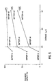
- Experiment 1-5 determined a relationship between density pitch and a discharge capacity for the batteries "A1", “A2” and “X”.
- the batteries used the corresponding alloys “a1", “a2” and “x” for the negative electrodes and the experimental results are shown in FIG. 5.
- the battery discharge is performed at various temperatures which are changed from 0°C, to -10°C and to -20°C. Each discharge capacity is compared to a discharge capacity at 25°C which represents a 100% discharge capacity.
- FIG. 5 shows that the batteries "A1" and “A2" of the present invention are less susceptible to discharge capacity reduction from low temperature discharging as compared to the battery "X".
- Experiment 1-6 tested a relationship between density pitch and internal pressure for the batteries “A1", “A2” and “X” and the experimental results are shown in FIG. 6.
- the batteries are charged at a 1C rate to 200% the normal charging capacity of the battery, and then the internal pressure for each battery is compared.
- FIG. 6 shows that the batteries "A1” and “A2" of the present invention have a significantly smaller internal pressure increase as compared to the battery "X".
- the hydrogen-absorbing alloy is prepared with Mm (Misch metal), Nickel (Ni), Cobalt (Co), Aluminum (A1) and Manganese (Mn) being measured in an element ratio of 1:3.2:0.8:0.2:0.8. These elements are mixed and melted in accordance with the same method used in the first embodiment.
- This alloy is used as a negative electrode and to produce a battery "B1".
- a second example of the second embodiment is similar to the above described first example of the second embodiment, however, the quenching speed is altered.
- the quenching speed is set higher than 500 °C/min after the slow-cooling to the nucleus formation temperature. This produces a hydrogen-absorbing alloy bulk having a composition represented by the formula MmNi 3.2 Co 0.8 Al 0.2 Mn 0.8 , and which is called "b2".
- the hydrogen-absorbing alloy "b2" is used to produce a negative electrode and then battery “B2" using the same method used for the first example.
- a comparative example is produced for comparison with the first and second examples.
- both the slow-cooling speed and quenching speed are set to less than 300 °C/min.
- the hydrogen-absorbing alloy "y” is used to produce a negative electrode and then a battery "Y" is prepared by the same method used in the first example.
- the batteries “B1" and “B2” of the present invention have excellent capacities, compared to the battery "Y” from the comparative example.
- the produced hydrogen-absorbing alloy has a non-stoichiometric composition ratio.
- a comparative example using the alloy "x" is used to produce a battery "X", in accordance with the comparative example of the first embodiment.
- Experiment 3-2 tested the discharge capacities of the batteries “C” and "X”.
- the batteries used the corresponding alloys “c” and “x” for the negative electrode and experimental results are shown in table 6.
- the discharge capacities of the battery are measured at a low temperature at -20 °C. Typical conditions for the measurements in this experiment are set to the same conditions as those used in experiment 1-2.
- the battery “C” of the present invention has an excellent capacity, compared to the battery "X" of the comparative example.
- Experiment 3-3 tested a relationship between discharge temperature and discharge capacities for the batteries “C” and “X”.
- the batteries used the corresponding alloys “c” and “x” for the negative electrode and the experimental results are shown in FIG. 7.
- Typical conditions for experiment 3-3 are set to the same as those used in experiment 1-3.
- FIG. 7 shows that reducing the discharge temperature has a lesser affect on the discharge capacity for the battery "C” compared to the battery "X".
- Experiment 3-4 tested a relationship between changing time and internal pressure of the batteries "C” and "X".
- the batteries used the corresponding alloys “c” and “x” for the negative electrode and the experimental results are shown in FIG. 8.
- Typical conditions for experiment 3-4 are set to the same as those used in experiment 1-4.
- the battery “C” of the present invention has a significantly smaller internal pressure increase from rapid charging as compared to the battery "X" of the comparative example.
- the hydrogen-absorbing alloy is prepared with Mm (Misch metal), Nickel (Ni), Cobalt (Co), Aluminum (Al), Manganese (Mn) and an additive of Boron (B) being measured in an element ratio of 1:3.1:0.9:0.2:0.6:0.1. These elements are then melted, and cooled using a cooling speed and a quenching speed less than 300 °C/min in accordance with the same method used by the first embodiment. This produces a hydrogen-absorbing alloy "d1" which is represented by the formula MmNi 3.1 Co 0.9 Al 0.2 Mn 0.6 B 0.1 . This alloy is used as a negative electrode and to produce a battery "D1".
- Tungsten (W) is used as an additive which replace the Boron in the first example.
- the hydrogen-absorbing alloy "d2" is used to produce a negative electrode, and then battery "D2" using the same method used by the first example.
- Molybdenum Mo is used as an additive which replaces the Boron in the first example.
- Thy hydrogen-absorbing alloy "d3" is used to produce a negative electrode and then battery "D3" using the same method used by the first example.
- a comparative example using the alloy "x" is used to produce a battery "X" in accordance with the comparative example of the first embodiment.
- experiment 4-1 a relationship between a Manganese (Mn) or Cobalt (Co) density difference and a density pitch was tested, typical results are shown in table 7.
- the conditions for the measurements in this experiment are the same as the conditions used in experiment 1-1.
- the alloys "d1", “d2” and “d3" of the present invention have enlarged Manganese (Mn) or Cobalt (Co) density differences and define density pitches which are spread out.
- the density difference is not less than about 6.0 wt% and the density pitch is not less than about 50 ⁇ m, respectively.
- Experiment 4-2 determined the discharge capacities of batteries “D1”, “D2”, “D3” and “X”.
- the batteries used the corresponding alloys “d1”, “d2”, “d3” and “x” for the negative electrode and the experimental results are shown in table 8.
- the discharge capacity of the battery is measured at a low temperature at -20 °C. Typical conditions for the measurements in this experiment are set to the same conditions as those used in experiment 1-2.
- the batteries "D1", D2" and “D3" of the present invention have excellent capacities compared to the battery "X" of the comparative example.
Landscapes
- Chemical & Material Sciences (AREA)
- Chemical Kinetics & Catalysis (AREA)
- Electrochemistry (AREA)
- General Chemical & Material Sciences (AREA)
- Battery Electrode And Active Subsutance (AREA)
Description
- This invention relates to a hydrogen-absorbing alloy for use as a negative electrode in an alkaline storage battery.
- Currently, research is being carried out to develop for hydrogen-absorbing alloys for use in a battery, and which are capable of absorbing and desorbing hydrogen reversibly. Also being developed are metal hydride storage batteries which use such hydrogen-absorbing alloys for their negative electrode. Metal hydride storage batteries, when compared to conventional Ni-Cd batteries or lead acid batteries, can be lighter and have a larger capacity.
- Proposed hydrogen-absorbing alloys for the negative electrode in the battery, include LaNi5, LaNi4Co and LaNi4Cu such as described in Japanese patent publication 59-49671, hydrogen-absorbing alloys of an Mm-Ni type (where the "Mm", a so-called "Misch Metal", is a mixture of rare earth elements, such as La, Ce, Nd, Pr, etc.) are also being developed. These alloys produce batteries that can obtain a high capacity.
- The above alloys are obtained by conventional methods, which typically produce alloys with homogeneous texture. This reduces cracking within the alloy. Therefore, when using these alloys for a negative electrode in a battery, the surface area does not increase, and there is a reduced reaction area. As a result, discharge characteristics of hydrogen descrbtion for the alloys at low temperatures deteriorate. Further, the oxygen absorbing capability of these alloys is inferior, thus, making rapid charging of the battery problematic.
- In typical conventional process for manufacturing the hydrogen-absorbing alloys, each component of the alloy is measured and mixed, melted in an arc furnace in an inert argon atmosphere, and cooled. Next, the alloys are held in a vacuum furnace and heat-treated at a high temperature (approximately 1000 °C) for a fixed period of time. This is an "annealing" heat treatment which causes homogenization of the hydrogen-absorbing alloys.
- To complete the electrode, the hydrogen-absorbing alloys are mechanically pulverized into granules. The granules are mixed into a paste with a conductive agent and a binder, such as powered polytetrafluoroethylene (PTFE). A coating of the paste is provided on a conductive substrate, such as a current collector comprising a punched metal plate. The current collector is then pressed to form the hydrogen-absorbing alloy electrode.
- Accordingly, it is a primary object of an embodiment of the present invention to provide a hydrogen-absorbing alloy electrode with improved electrode characteristics, such as improved discharge characteristics in low temperatures.
- Another object of an embodiment of the present invention is to provide a hydrogen-absorbing alloy electrode with improved electrode characteristics, such as improved high-rate charge characteristics in the low temperatures.
- Still another object of an embodiment of the present invention is to provide a hydrogen-absorbing alloy electrode with a large discharge capacity.
- According to the present invention there is provided a hydrogen-absorbing alloy electrode comprising a conductive substrate on which is provided a hydrogen-absorbing alloy in a single phase crystal system and composed of at Icast three elements; wherein one of said at least three elements has a density distribution profile as provided with measurement by EPMA which for a 2 µm3 sample of the alloy has at least two adjacent high density peaks and a lowest density point between said at least two adjacent high density peaks, and wherein a density difference between one of said at least two adjacent high density peaks and said lowest density point is not less then 3.0 wt% and a distance between said two adjacent high density peaks is not less than 20 µm.
- The alloy preferably has the formula ANiaCobMncXd, in which A is a Misch Metal or mixture of rare earth elements include Lanthanum, the ranges of "a", "b", "c" and "d" are respectively defined by 2.5 ≦ a ≦ 3.5, 0 ≦ b ≦ 1.5, 0 ≦ c ≦ 1 and 0 ≦ d ≦ 0.3, the value of a+b+c+d is 3.85 to 5, and X is one of the elements iron (Fe), Copper (Cu), Molybdenum (Mo), Tungsten (W), Boron (B), Aluminium (Al), Silicon (Si) and Tin (Sn).
- The single phase crystal system may be a hexagonal crystal system.
- The present invention also provides a hydrogen-absorbing alloy for a negative electrode, the alloy having a single phase crystal system of the formula ANiaCobMncXd, in which A is a Misch Metal or mixture of rare earth elements including Lanthanum, the ranges of "a", "b", "c" and "d" are respectively defined by 2.5 ≦ a ≦ 3.5, 0 ≦ b≦1.5, 0≦c≦1 and 0 ≦ d ≦ 0.3, the value of a+b+c+d is 3.85 to 5, and X is one of the elements iron (Fe), Copper (Cu), Molybdenum (Mo), Tungsten (W), Boron (B), Aluminium (Al), Silicon (Si) and Tin (Sn);
wherein one of said at least three elements has a density distribution profile which for a 2 µm3 sample of the alloy has at least two adjacent high density peaks and a lowest density point between said at least two adjacent high density peaks, and wherein a density difference between one of said at least two adjacent high density peaks and said lowest density point is not less then 3.0 wt% and a distance between said two adjacent high density peaks is not less than 20 µm. - The present invention further provides a method of manufacturing a hydrogen-absorbing alloy by cooling a melted mixture of the alloy at a first cooling speed until a nucleus formation temperature is reached and then by quenching at a second cooling speed faster than said first cooling speed, wherein said nucleus fonnation temperature ranges from about 1200 °C to about 1300 °C, and said second cooling speed is greater than 300 °C/min.
- The second cooling speed may be greater than 500°C/min.
- A method of manufacturing a hydrogen-absorbing alloy electrode is also provided, the method comprising manufacturing a hydrogen-absorbing alloy as described above and placing said alloy on a conductive substrate.
- These and other objects, advantages and features of the invention will become apparent from the following description thereof taken in conjunction with the accompanying drawings which illustrate specific embodiments of the invention. In the drawings:
- FIG. 1 is a cross-sectional illustration of a battery in accordance with an embodiment of the present invention;
- FIG. 2 is a graph showing a part of the density distribution profile for a hydrogen-absorbing alloy in accordance with a first embodiment of the present invention;
- FIG. 3 is a graph showing the relationship between temperature and the discharge capacity of a battery in accordance with a first embodiment of the present invention;
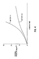
- FIG. 4 is a graph showing the relationship between the charging time and an internal pressure of a battery in accordance with a first embodiment of the present invention;
- FIG. 5 is a graph showing the relationship between the distance between two adjacent high density peaks and a discharge capacity of a battery in accordance with a first embodiment of the present invention;
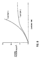
- FIG. 6 is a graph showing the relationship between the distance between the two adjacent high density peaks and internal pressure of a battery in accordance with a first embodiment of the present invention;
- FIG. 7 is a graph showing the relationship between temperature of a battery and the discharge capacity in accordance with a further embodiment of the present invention;
- FIG. 8 is a graph showing the relationship between the charging time and internal pressure of a battery in accordance with a further embodiment of the present invention;
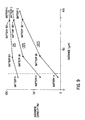
- FIG. 9 is a graph showing the relationship between the discharge between the two adjacent high density peaks and a discharge capacity of a battery in accordance with said further embodiment of the present invention.
-
- The following detailed description is of the best presently contemplated mode of carrying out the invention by the inventors. This description should not to be taken in a limiting sense, but is made merely for the purpose of illustrating general principles of embodiments of the invention. The scope of the invention is best defined by the appended claims.
- The hydrogen-absorbing alloys according to embodiments of the present invention composed of at least three elements. However, the crystal structure of the alloys are mainly in a single phase crystal system. One of the at least three elements is partially condensed in an alloy mixture, and high density portions may be obtained. One of the three elements is measured with EPMA (Electron Probe Micro Analysis), which provides a density distribution profile with at least two adjacent high density peaks and a lowest density point between the at least two adjacent high density peaks. One of the three elements has a density difference between one of the at least two adjacent high density peaks and the lowest density point of not less than about 3.0 wt%. Further, the distance between the two adjacent high density peaks is not less than about 20 µm. This distance is defined by a real length between the two adjacent high density peaks measured by the EPMA method. This distance in embodiments of the present invention has the same meaning as a density pitch which is defined in this specification.
- For the avoidance of doubt, EPMA is an analysis performed by emitting an electron beam towards a small portion of a sample, in response to which an element of the sample will emit a characteristic X-ray. The wavelength, energy and intensity of this characteristic X-ray may then be analysed to identify both the type of element and its density (i.e. its quantity per unit volume). The so-called density profile of the element is obtained by linearly moving the irradiating electron beam across the sample.
- One skilled in the art of EPMA would appreciate that the term "density distribution profile", used in the present application, refers to the result of a linear analysis by EPMA. One example of such a density distribution profile is shown in figure 2 of the present application. Referring to figure 2, the horizontal axis represents the physical position of the sample and the vertical axis represents the existing concentration (or density) of the analysed element in the sample. The existing concentration may be designated as either a percent (%) or as a weight percent (wt%), and may be defined according to the following formula:
- Wherein,
- "a" represents the intensity of the characteristic X-ray of the sample, and
- "b" represents the intensity of the characteristic X-ray of a standard element.
-
- The term "high density peak" is a standard term referring to the point at which the differential value of the density (measured as a function of distance) changes from positive to negative. Two such high density peaks are shown, for example, in figure 2 of the present application.
- The term "density pitch", which is also a standard term, refers to the distance between two adjacent high density peaks. That is, the term "density pitch" as used in the present application refers to the pitch "or distance" between adjacent peaks of high densities.
- The above hydrogen-absorbing alloy may be in a single phase crystal system. However, components of portions of the alloy are different. Accordingly, equilibrium-pressure difference from absorbing hydrogen between two portions of the alloy may be created. Further, portions having a low equilibrium-pressure can more easily absorb hydrogen. Therefore, cracks are easily created in the alloy, and the surface area of the hydrogen-absorbing alloys are increased. As a result, the reaction area is also increased.
- In a first embodiment of the present invention, hydrogen-absorbing alloys are prepared and used to form batteries. FIG. 1 is a cross-sectional illustration of a battery according to a first embodiment of the present invention. In FIG. 1, the battery has a
positive electrode 1 of a sintered type nickel hydroxide electrode, anegative electrode 2 of hydrogen-absorbing alloy and aseparator 3. Theseparator 3 is impregnated with an alkaline electrolyte, and spirally wound to insulate thepositive electrode 1 from thenegative electrode 2. This forms anelectrode body 4. Theelectrode body 4 is set in an outer case 6, which acts as a negative terminal for the battery. The outer case 6 and thenegative electrode 2 are electrically connected together by a negativeconductive lead 5. An opening in the outer case 6 is closed off by a cap 8 and a packing 7. Inside part of the cap 8, a coiled spring 9 is arranged. Once internal pressure in the battery increases, and the coiled spring is pressed in the direction "A". Thus, internal gas may be released into the atmosphere. The cap 8 and thepositive electrode 1 are electrically connected together by a positiveconductive lead 10. - The above cylindrical type metal hydrogen battery may be produced in accordance with the process described below. To prepare the hydrogen-absorbing alloy, Mm (so-called Misch Metal), Nickel (Ni), Cobalt (Co), Aluminum (Al) and Manganese (Mn) are measured in an element ratio of 1:3.2:1:0.2:0.6. These elements are then melted in a high frequency melting furnace in an argon atmosphere (or other inert atmosphere) to form a melted mixture. Next, the melted mixture is slowly cooled at less than a 50 °C/min cooling speed to reach a nucleus formation temperature (ranging from about 1200 °C to about 1300 °C). Once the mixture temperature reaches less than the nucleus formation temperature, the mixture is quenched at a quenching speed ranging from 300 °C/min to 500 °C/min. This produces a hydrogen-absorbing alloy bulk with a composition represented by the formula MmNi3.2Co1.0Al0.2Mn0.6. The above produced alloy is called "a1".
- The hydrogen-absorbing alloy "a1" is then mechanically pulverized into granules with an average size of 50 µm. Next, the granules are kneaded with polyethyleneoxide (PEO), water-soluble binder, to obtain a paste. The paste is applied to a punched metal conductive substrate, on both sides, and then dried to produce a
negative electrode 2. Thenegative electrode 2 and thepositive electrode 1, with theseparator 3 interposed between them, are wound to produce theelectrode body 4. Theelectrode body 4 is then inserted into the outer case 6, and a 30 wt% KOH electrolyte solution is poured into the outer case 6. Then, the outer case 6 is closed off by the cap 8 and packing 7. This produces a battery called battery "A". - A second example is similar to the above described first example, however the quenching speed is altered. The quenching speed is set higher than 500 °C/min. This produces a hydrogen-absorbing alloy bulk having the same elements as described in the first example. This alloy is called "a2".
- The hydrogen-absorbing alloy "a2" is used to produce a negative electrode, and then a battery "A2" using the negative electrode is prepared by the same method used in the above first example.
- A comparative example is produced for comparison with the above first and second examples. To produce the comparative example, the cooling speed of both the slow-cooling and the quenching is altered. These cooling speeds are set at less than 300 °C/min. This also produces a hydrogen-absorbing alloy bulk having the same elements as described in the first example. This alloy is called "x". The hydrogen-absorbing alloy "x" is used to produce a negative electrode and then a battery "X" is prepared by the same method used in the above first example.
- Several experiments were performed on the above battery examples. The purpose was to determine the battery characteristics and to compare the battery example. Below is a description of the experiments performed.
- In experiment 1-1, a relationship between a Manganese (Mn) density difference and a density pitch in the alloy was tested, and the results are shown in table 1. The density pitch is the distance between two adjacent high density peaks. In the experiment 1-1, a distance between portions of two adjacent segregated elements in the hydrogen-absorbing alloy is measured in a 2 µm3 volume by linear analysis methods. FIG. 2 graphically illustrates the relationship between the density difference and the density pitch (distance). In FIG. 2 a horizontal line represents the density pitch (the distance between the two adjacent high density peaks) and a vertical line represents a density difference for one of the elements. Therefore, a height for one of the density peaks defines the density differences.
- As shown in table 1, the alloys "a1" and "a2" of the present invention have enlarged Manganese (Mn) density differences and exhibit density pitches, which are spread out. In the alloys "a1" and "a2", the density differences are not less than about 3.0 wt% and the density pitches are not less than about 20 µm, respectively.
Alloy Density difference (wt%) Density pitch (µm) a1 3.0 20 a2 5.7 63 x 1.1 less than 15 - Experiment 1-2 test the discharge capacities of batteries "A1", "A2" and "X". The batteries used the corresponding alloys "a1", "a2" and "x" for the negative electrode and the experiment 1-2 results are shown in table 2. The discharge capacity of the battery was measured at a low temperature at -20 °C. To conduct the experiment, each battery is charged at room temperature at 1C rate to provide a full-charge. Next, the battery is cooled to -20 °C and the battery is discharged until a 0.8 V battery voltage is measured. In table 2, a discharge capacity at 20 °C (room temperature) is 100 %.
Alloy Battery Discharge capacity (%) a1 A1 32 a2 A2 64 x X 5 - As shown in table 2, the batteries "A1" and "A2" of the present invention have excellent capacities, compared to the battery "X" from the comparative example.
- Experiment 1-3 tested a relationship between discharge temperature and discharge capacity for the batteries "A2" and "X". The batteries used the corresponding alloys "a2" and "x" for the negative electrode and the experimental results are shown in FIG. 3. The discharge capacity for each battery was measured by changing the discharge temperature. As shown in FIG. 3, a discharge capacity at 20 °C (room temperature) is 100%. FIG. 3 shows that reducing the discharge temperature has a lesser affect on the discharge capacity for the batteries "A1" and "A2" compared to the battery "X" from the comparative example.
- Experiment 1-4 tested a relationship between charging time and internal pressure of the batteries "A2" and "X". The batteries used the corresponding alloys "a2" and "x" for the negative electrode and the experimental results are shown in FIG. 4. The charging current for this experiment was set at a 2 C rate. As shown in FIG. 4, the battery "A2" of the present invention has a significantly smaller internal pressure increase from rapid charging as compared to the battery "X".
- Experiment 1-5 determined a relationship between density pitch and a discharge capacity for the batteries "A1", "A2" and "X". The batteries used the corresponding alloys "a1", "a2" and "x" for the negative electrodes and the experimental results are shown in FIG. 5. The battery discharge is performed at various temperatures which are changed from 0°C, to -10°C and to -20°C. Each discharge capacity is compared to a discharge capacity at 25°C which represents a 100% discharge capacity. FIG. 5 shows that the batteries "A1" and "A2" of the present invention are less susceptible to discharge capacity reduction from low temperature discharging as compared to the battery "X".
- Experiment 1-6 tested a relationship between density pitch and internal pressure for the batteries "A1", "A2" and "X" and the experimental results are shown in FIG. 6. For this experiment, the batteries are charged at a 1C rate to 200% the normal charging capacity of the battery, and then the internal pressure for each battery is compared. FIG. 6 shows that the batteries "A1" and "A2" of the present invention have a significantly smaller internal pressure increase as compared to the battery "X".
- The results of above experiments, 1-1 to 1-6, show that a density pitch between two adjacent portions are preferably greater than about 20 µm.
- In a second embodiment of the present invention, the hydrogen-absorbing alloy is prepared with Mm (Misch metal), Nickel (Ni), Cobalt (Co), Aluminum (A1) and Manganese (Mn) being measured in an element ratio of 1:3.2:0.8:0.2:0.8. These elements are mixed and melted in accordance with the same method used in the first embodiment. This produces a hydrogen-absorbing alloy "b1" represented by the formula MmNi3.2Co0.8Al0.2Mn0.8. This alloy is used as a negative electrode and to produce a battery "B1".
- A second example of the second embodiment is similar to the above described first example of the second embodiment, however, the quenching speed is altered. The quenching speed is set higher than 500 °C/min after the slow-cooling to the nucleus formation temperature. This produces a hydrogen-absorbing alloy bulk having a composition represented by the formula MmNi3.2Co0.8Al0.2Mn0.8, and which is called "b2".
- The hydrogen-absorbing alloy "b2" is used to produce a negative electrode and then battery "B2" using the same method used for the first example.
- A comparative example is produced for comparison with the first and second examples. To produce the comparative example, both the slow-cooling speed and quenching speed are set to less than 300 °C/min. This produces a hydrogen-absorbing alloy bulk having the same elements as described in the first example. This alloy is called "y". The hydrogen-absorbing alloy "y" is used to produce a negative electrode and then a battery "Y" is prepared by the same method used in the first example.
- Several experiments were performed on the above battery examples. The purpose was to determine the battery characteristics and to compare the battery example. Below is a description of the experiments performed.
- In experiment 2-1, a relationship between a Manganese (Mn) density difference and a density pitch was tested, and the results are shown in table 3. As shown in table 3, the alloys "b1" and "b2" of the present invention have enlarged Manganese (Mn) density differences and define density pitches which are spread out. In the alloys "b1" and "b2", the density differences are not less than about 3.2 wt% and the density pitches are not less than about 42 µm, respectively.
Alloy Density difference (wt%) Density pitch (µm) b1 3.2 42 b2 6.0 88 y 1.3 less than 18 - Experiment 2-1 tested the discharge capacities of batteries "B1", "B2" and "Y". The batteries used the corresponding alloys "b1", "b2" and "y" for the negative electrode and the experimental results are shown in table 4. The discharge capacity of the batteries is measured at low temperature at -20 °C. Typical conditions for the measurements in this experiment are set to the same conditions as those used in experiment 1-2.
Alloy Battery Discharge capacity (%) b1 B1 38 b2 B2 70 Y Y 3 - As shown in the table 4, the batteries "B1" and "B2" of the present invention have excellent capacities, compared to the battery "Y" from the comparative example. The produced hydrogen-absorbing alloy has a non-stoichiometric composition ratio.
- A comparative example using the alloy "x" is used to produce a battery "X", in accordance with the comparative example of the first embodiment.
- Several experiments were performed on the above battery examples. The purpose was to determine the battery characteristics and to compare the battery example. Below is a description of the experiments performed.
- In experiment 3-1, a relationship between a Manganese (Mn) density difference and a density pitch was tested and typical results are shown in table 5. The conditions for the measurements in this experiment are the same as the conditions used in experiment 1-1. As shown in table 5, the alloy "c" of the present invention has an enlarged Manganese (Mn) density differences and defines a density pitch, which is spread out. In the alloy "c", the density difference is less than about 10 wt% and the density pitch is not less than about 97 µm, respectively.
Alloy Density difference (wt%) Density pitch (µm) c 10 97 x 1.1 less than 15 - Experiment 3-2 tested the discharge capacities of the batteries "C" and "X". The batteries used the corresponding alloys "c" and "x" for the negative electrode and experimental results are shown in table 6. The discharge capacities of the battery are measured at a low temperature at -20 °C. Typical conditions for the measurements in this experiment are set to the same conditions as those used in experiment 1-2.
Alloy Battery Discharge capacity (%) c C 75 x X 5 - As shown in table 6, the battery "C" of the present invention has an excellent capacity, compared to the battery "X" of the comparative example.
- Experiment 3-3 tested a relationship between discharge temperature and discharge capacities for the batteries "C" and "X". The batteries used the corresponding alloys "c" and "x" for the negative electrode and the experimental results are shown in FIG. 7. Typical conditions for experiment 3-3 are set to the same as those used in experiment 1-3. In FIG. 7 shows that reducing the discharge temperature has a lesser affect on the discharge capacity for the battery "C" compared to the battery "X".
- Experiment 3-4 tested a relationship between changing time and internal pressure of the batteries "C" and "X". The batteries used the corresponding alloys "c" and "x" for the negative electrode and the experimental results are shown in FIG. 8. Typical conditions for experiment 3-4 are set to the same as those used in experiment 1-4. As shown in FIG. 8, the battery "C" of the present invention has a significantly smaller internal pressure increase from rapid charging as compared to the battery "X" of the comparative example.
- Experiment 3-5 tested a relationship between density pitch and a discharge capacity of the batteries "C", "B1", "B2" and "X". The batteries used the corresponding alloys "c", b1", "b2" and "x" for the negative electrode and the experimental results are shown in FIG. 9. The batteries "B1" and "B2" are prepared in accordance with the above described second embodiment. The battery discharge is performed at various temperatures which are from changed from 0°C, to -10°C and to -20°C. Each discharge capacity is compared to a discharge capacity at 25°C which represents a 100% discharge capacity. FIG. 9 shows that the batteries "C", "B1" and "B2" of the present invention are less susceptible to discharge capacity reduction from such low temperature discharging as compared to the battery "X".
- Experiment 3-6 tested a relationship between density pitch and internal pressure for the batteries "C", "B1", "B2" and "X". For this experiment, the batteries were charged at a 1C rate to 200% the normal charging capacity of the battery, and then the internal pressure for each battery was compared. The results showed that the batteries "C", "B1" and "B2" of the present invention have a significantly smaller increase in internal pressure as compared to the battery "X".
- The results of the above experiments, 3-1 to 3-6, show that the density pitch is more preferable more than about 40 µm.
- In a fourth embodiment of the present invention, the hydrogen-absorbing alloy is prepared with Mm (Misch metal), Nickel (Ni), Cobalt (Co), Aluminum (Al), Manganese (Mn) and an additive of Boron (B) being measured in an element ratio of 1:3.1:0.9:0.2:0.6:0.1. These elements are then melted, and cooled using a cooling speed and a quenching speed less than 300 °C/min in accordance with the same method used by the first embodiment. This produces a hydrogen-absorbing alloy "d1" which is represented by the formula MmNi3.1Co0.9Al0.2Mn0.6B0.1. This alloy is used as a negative electrode and to produce a battery "D1".
- In a second example of the fourth embodiment Tungsten (W) is used as an additive which replace the Boron in the first example. This produces a hydrogen-absorbing alloy bulk having a composition represented by the formula MmNi3.1Co0.9Al0.2Mn0.6W0.1 and which is called "d2". The hydrogen-absorbing alloy "d2" is used to produce a negative electrode, and then battery "D2" using the same method used by the first example.
- In a third example of the fourth embodiment, Molybdenum (Mo) is used as an additive which replaces the Boron in the first example. This produces a hydrogen-absorbing alloy bulk having a composition represented by the formula MmNi3.1Co0.9Al0.2Mn0.6Mo0.1 and which is called "d3". Thy hydrogen-absorbing alloy "d3" is used to produce a negative electrode and then battery "D3" using the same method used by the first example.
- A comparative example using the alloy "x" is used to produce a battery "X" in accordance with the comparative example of the first embodiment.
- Several experiments were performed on the above battery examples. The purpose was to determine the battery characteristics and to compare the battery example. Below is a description of the experiments performed.
- In experiment 4-1, a relationship between a Manganese (Mn) or Cobalt (Co) density difference and a density pitch was tested, typical results are shown in table 7. The conditions for the measurements in this experiment are the same as the conditions used in experiment 1-1. As shown in table 7, the alloys "d1", "d2" and "d3" of the present invention have enlarged Manganese (Mn) or Cobalt (Co) density differences and define density pitches which are spread out. In the alloys "d1", "d2" and "d3", the density difference is not less than about 6.0 wt% and the density pitch is not less than about 50 µm, respectively.
Alloy Density difference of Mn (wt%) Density difference of Co (wt%) Density pitch (µm) d1 - 6.0 50 d2 8.6 - 63 d3 7.1 - 64 x 1.1 - 15 - Experiment 4-2 determined the discharge capacities of batteries "D1", "D2", "D3" and "X". The batteries used the corresponding alloys "d1", "d2", "d3" and "x" for the negative electrode and the experimental results are shown in table 8. The discharge capacity of the battery is measured at a low temperature at -20 °C. Typical conditions for the measurements in this experiment are set to the same conditions as those used in experiment 1-2.
Alloy Battery Discharge capacity (%) d1 D1 69 d2 D2 72 d3 D3 74 x X 5 - As shown in table 8, the batteries "D1", D2" and "D3" of the present invention have excellent capacities compared to the battery "X" of the comparative example.
Claims (8)
- A hydrogen-absorbing alloy electrode comprising:a conductive substrate on which is provided a hydrogen-absorbing alloy in a single phase crystal system and composed of at least three elements; wherein one of said at least three elements has a density distribution profile as provided with measurement by EPMA which for a 2 µm3 sample of the alloy has at least two adjacent high density peaks and a lowest density point between said at least two adjacent high density peaks, and wherein a density difference between one of said at least two adjacent high density peaks and said lowest density point is not less then 3.0 wt% and a distance between said two adjacent high density peaks is not less than 20 µm.
- A hydrogen-absorbing alloy electrode according to claim 1, wherein said alloy has the formula ANiaCobMncXd, in which A is a Misch Metal or mixture of rare earth elements including Lanthanum in the range selected from 20% to 50%, the ranges of "a", "b", "c" and "d" are respectively defined by 2.5 ≦ a ≦ 3.5, 0 ≦ b ≦ 1.5, 0 ≦c ≦ 1 and 0 ≦ d ≦ 0.3, the value of a+b+c+d is 3.85 to 5, and X is one of the elements iron (Fe), Copper (Cu), Molybdenum (Mo), Tungsten (W), Boron (B), Aluminium (Al), Silicon (Si) and Tin (Sn).
- A hydrogen-absorbing alloy electrode according to claim 1 or claim 2, wherein said single phase crystal system is a hexagonal crystal system.
- A hydrogen-absorbing alloy for a negative electrode, the alloy having a single phase crystal system of the formula ANiaCobMncXd, in which A is a Misch Metal or mixture of rare earth elements including Lanthanum in the range selected from 20% to 50%, the ranges of "a", "b", "c" and "d" are respectively defined by 2.5 ≦ a ≦ 3.5, 0 ≦ b ≦ 1.5, 0 ≦ c ≦ 1 and 0 ≦ d ≦ 0.3, the value of a+b+c+d is 3.85 to 5, and X is one of the elements iron (Fe), Copper (Cu), Molybdenum (Mo), Tungsten (W), Boron (B), Aluminium (Al), Silicon (Si) and Tin (Sn);wherein one of said at least three elements has a density distribution profile as provided with measurement by EPMA which for a 2 µm3 sample of the alloy has at least two adjacent high density peaks and a lowest density point between said at least two adjacent high density peaks, and wherein a density difference between one of said at least two adjacent high density peaks and said lowest density point is not less then 3.0 wt% and a distance between said two adjacent high density peaks is not less than 20 µm.
- A hydrogen-absorbing alloy according to claim 4, wherein said single phase crystal system is a hexagonal crystal system.
- A method of manufacturing a hydrogen-absorbing alloy according to any preceding claim, wherein said hydrogen-absorbing alloy is produced by cooling a melted mixture of said hydrogen-absorbing alloy at a first cooling speed until a nucleus formation temperature is reached and then by quenching at a second cooling speed faster than said first cooling speed, wherein said nucleus formation temperature ranges from about 1200 °C to about 1300 °C, and said second cooling speed is greater than 300 °C/min.
- A method according to claim 6, wherein said second cooling speed is greater than 500°C/min.
- A method of manufacturing a hydrogen-absorbing alloy electrode, comprising manufacturing a hydrogen-absorbing alloy in accordance with claim 6 or claim 7, and placing said alloy on a conductive substrate.
Applications Claiming Priority (3)
| Application Number | Priority Date | Filing Date | Title |
|---|---|---|---|
| JP4869792 | 1992-03-05 | ||
| JP4869792 | 1992-03-05 | ||
| JP48697/92 | 1992-03-05 |
Publications (2)
| Publication Number | Publication Date |
|---|---|
| EP0560535A1 EP0560535A1 (en) | 1993-09-15 |
| EP0560535B1 true EP0560535B1 (en) | 1999-11-03 |
Family
ID=12810504
Family Applications (1)
| Application Number | Title | Priority Date | Filing Date |
|---|---|---|---|
| EP93301638A Expired - Lifetime EP0560535B1 (en) | 1992-03-05 | 1993-03-04 | Hydrogen-absorbing alloy for negative electrode |
Country Status (3)
| Country | Link |
|---|---|
| US (1) | US5468260A (en) |
| EP (1) | EP0560535B1 (en) |
| DE (1) | DE69326907T2 (en) |
Families Citing this family (5)
| Publication number | Priority date | Publication date | Assignee | Title |
|---|---|---|---|---|
| KR960024447A (en) * | 1994-12-28 | 1996-07-20 | 윤종용 | Battery withstand voltage measurement device |
| DE19639440C2 (en) * | 1995-09-29 | 2001-05-10 | Toshiba Kawasaki Kk | Hydrogen absorbing alloy for a battery and use of the alloy in secondary nickel metal hydride batteries |
| US6110304A (en) * | 1995-11-17 | 2000-08-29 | Sanyo Electric Co., Ltd. | Hydrogen-absorbing alloy electrode for alkaline storage batteries |
| JP3553750B2 (en) * | 1996-11-29 | 2004-08-11 | 三洋電機株式会社 | Method for producing hydrogen storage alloy for alkaline storage battery |
| US8388955B2 (en) * | 2003-03-03 | 2013-03-05 | Xencor, Inc. | Fc variants |
Family Cites Families (7)
| Publication number | Priority date | Publication date | Assignee | Title |
|---|---|---|---|---|
| FR2311858A1 (en) * | 1975-05-23 | 1976-12-17 | Anvar | LANTHANE AND NICKEL-BASED ALLOYS AND THEIR ELECTROCHEMICAL APPLICATIONS |
| NL8303630A (en) * | 1983-10-21 | 1985-05-17 | Philips Nv | ELECTROCHEMICAL CELL WITH STABLE HYDRIDE-FORMING MATERIALS. |
| JP2771592B2 (en) * | 1989-04-18 | 1998-07-02 | 三洋電機株式会社 | Hydrogen storage alloy electrode for alkaline storage batteries |
| NL8901776A (en) * | 1989-07-11 | 1991-02-01 | Philips Nv | ELECTROCHEMICAL CELL. |
| US4948423A (en) * | 1989-07-21 | 1990-08-14 | Energy Conversion Devices, Inc. | Alloy preparation of hydrogen storage materials |
| US5135589A (en) * | 1990-04-16 | 1992-08-04 | Fetcenko Michael A | Metastable hydrogen storage alloy material |
| US5376474A (en) * | 1993-02-05 | 1994-12-27 | Sanyo Electric Co., Ltd. | Hydrogen-absorbing alloy for a negative electrode and manufacturing method therefor |
-
1993
- 1993-03-04 DE DE69326907T patent/DE69326907T2/en not_active Expired - Fee Related
- 1993-03-04 EP EP93301638A patent/EP0560535B1/en not_active Expired - Lifetime
-
1994
- 1994-12-02 US US08/352,722 patent/US5468260A/en not_active Expired - Fee Related
Also Published As
| Publication number | Publication date |
|---|---|
| DE69326907T2 (en) | 2000-05-11 |
| EP0560535A1 (en) | 1993-09-15 |
| DE69326907D1 (en) | 1999-12-09 |
| US5468260A (en) | 1995-11-21 |
Similar Documents
| Publication | Publication Date | Title |
|---|---|---|
| US6338917B1 (en) | Alkaline storage battery | |
| KR20020064363A (en) | Alloy for hydrogen storage, secondary battery, hybrid car and electric vehicle | |
| EP0609609B1 (en) | Method for manufacturing a hydrogen-absorbing alloy for a negative electrode | |
| EP0867956B1 (en) | Hydrogen storage alloy electrode | |
| US5043233A (en) | Hydrogen-absorbing alloy electrode for use in an alkaline storage cell and its manufacturing method | |
| US6524746B2 (en) | Hydrogen absorbing alloy powder and process for producing same | |
| JP2002042805A (en) | Non-aqueous electrolyte secondary battery | |
| US5468260A (en) | Hydrogen-absorbing alloy for negative electrode | |
| US6733724B1 (en) | Hydrogen absorbing alloy and nickel-metal hydride rechargeable battery | |
| EP0739990B1 (en) | Hydrogen storage alloy and electrode therefrom | |
| KR19980085375A (en) | Micro Metals and Nickel-Based Hydrogen Storage Alloys for Ni / MH Secondary Batteries | |
| EP0867957B1 (en) | Negative electrode for alkaline storage batteries | |
| US6342318B1 (en) | Hydrogen absorbing alloy electrode and process for producing same | |
| US6605387B1 (en) | Alkaline storage battery | |
| USRE34471E (en) | Hydrogen-absorbing alloy electrode for use in an alkaline storage cell and its manufacturing method | |
| JP3322452B2 (en) | Rare earth hydrogen storage alloy for alkaline storage batteries | |
| KR100217712B1 (en) | Electrode Plate and Manufacturing Method Thereof | |
| EP1096584A1 (en) | Hydrogen absorbing alloy for alkaline storage battery and method for production thereof, and hydrogen absorbing alloy electrode for alkaline storage battery and method for production thereof | |
| JP2000353520A (en) | Alkaline storage battery | |
| JP2005158533A (en) | Hydrogen storage alloy electrode for alkaline storage battery, and alkaline storage battery using the same | |
| JPH05266916A (en) | Metal-hydrogen alkaline storage battery | |
| JPH09129227A (en) | Nickel-metal hydride battery | |
| JP2000353542A (en) | Alkaline storage battery | |
| JPH08287908A (en) | Hydrogen storage alloy electrode | |
| JPH06111817A (en) | Metal/hydride secondary battery |
Legal Events
| Date | Code | Title | Description |
|---|---|---|---|
| PUAI | Public reference made under article 153(3) epc to a published international application that has entered the european phase |
Free format text: ORIGINAL CODE: 0009012 |
|
| AK | Designated contracting states |
Kind code of ref document: A1 Designated state(s): DE FR |
|
| 17P | Request for examination filed |
Effective date: 19931108 |
|
| 17Q | First examination report despatched |
Effective date: 19960118 |
|
| GRAG | Despatch of communication of intention to grant |
Free format text: ORIGINAL CODE: EPIDOS AGRA |
|
| GRAG | Despatch of communication of intention to grant |
Free format text: ORIGINAL CODE: EPIDOS AGRA |
|
| GRAH | Despatch of communication of intention to grant a patent |
Free format text: ORIGINAL CODE: EPIDOS IGRA |
|
| GRAH | Despatch of communication of intention to grant a patent |
Free format text: ORIGINAL CODE: EPIDOS IGRA |
|
| GRAA | (expected) grant |
Free format text: ORIGINAL CODE: 0009210 |
|
| AK | Designated contracting states |
Kind code of ref document: B1 Designated state(s): DE FR |
|
| REF | Corresponds to: |
Ref document number: 69326907 Country of ref document: DE Date of ref document: 19991209 |
|
| ET | Fr: translation filed | ||
| PLBE | No opposition filed within time limit |
Free format text: ORIGINAL CODE: 0009261 |
|
| STAA | Information on the status of an ep patent application or granted ep patent |
Free format text: STATUS: NO OPPOSITION FILED WITHIN TIME LIMIT |
|
| 26N | No opposition filed | ||
| REG | Reference to a national code |
Ref country code: FR Ref legal event code: ST |
|
| REG | Reference to a national code |
Ref country code: FR Ref legal event code: RN |
|
| REG | Reference to a national code |
Ref country code: FR Ref legal event code: FC |
|
| REG | Reference to a national code |
Ref country code: FR Ref legal event code: FC |
|
| PGFP | Annual fee paid to national office [announced via postgrant information from national office to epo] |
Ref country code: FR Payment date: 20080311 Year of fee payment: 16 Ref country code: DE Payment date: 20080228 Year of fee payment: 16 |
|
| PG25 | Lapsed in a contracting state [announced via postgrant information from national office to epo] |
Ref country code: DE Free format text: LAPSE BECAUSE OF NON-PAYMENT OF DUE FEES Effective date: 20091001 |
|
| PG25 | Lapsed in a contracting state [announced via postgrant information from national office to epo] |
Ref country code: FR Free format text: LAPSE BECAUSE OF NON-PAYMENT OF DUE FEES Effective date: 20090331 |
|
| REG | Reference to a national code |
Ref country code: FR Ref legal event code: ST Effective date: 20100630 |