EP0560225B1 - Methods of winding armatures with modified side pattern - Google Patents
Methods of winding armatures with modified side pattern Download PDFInfo
- Publication number
- EP0560225B1 EP0560225B1 EP93103557A EP93103557A EP0560225B1 EP 0560225 B1 EP0560225 B1 EP 0560225B1 EP 93103557 A EP93103557 A EP 93103557A EP 93103557 A EP93103557 A EP 93103557A EP 0560225 B1 EP0560225 B1 EP 0560225B1
- Authority
- EP
- European Patent Office
- Prior art keywords
- coils
- armature
- shaft
- winding
- wound
- Prior art date
- Legal status (The legal status is an assumption and is not a legal conclusion. Google has not performed a legal analysis and makes no representation as to the accuracy of the status listed.)
- Expired - Lifetime
Links
- 238000004804 winding Methods 0.000 title claims description 49
- 238000000034 method Methods 0.000 title claims description 14
- 238000004873 anchoring Methods 0.000 claims 6
- 230000008901 benefit Effects 0.000 description 7
- 240000000972 Agathis dammara Species 0.000 description 2
- 229920002871 Dammar gum Polymers 0.000 description 2
- 230000009977 dual effect Effects 0.000 description 2
- 230000001133 acceleration Effects 0.000 description 1
- 238000001816 cooling Methods 0.000 description 1
- 238000010586 diagram Methods 0.000 description 1
- WABPQHHGFIMREM-UHFFFAOYSA-N lead(0) Chemical compound [Pb] WABPQHHGFIMREM-UHFFFAOYSA-N 0.000 description 1
- 230000004048 modification Effects 0.000 description 1
- 238000012986 modification Methods 0.000 description 1
- 238000009828 non-uniform distribution Methods 0.000 description 1
- 238000011179 visual inspection Methods 0.000 description 1
Images


Classifications
-
- H—ELECTRICITY
- H02—GENERATION; CONVERSION OR DISTRIBUTION OF ELECTRIC POWER
- H02K—DYNAMO-ELECTRIC MACHINES
- H02K23/00—DC commutator motors or generators having mechanical commutator; Universal AC/DC commutator motors
- H02K23/26—DC commutator motors or generators having mechanical commutator; Universal AC/DC commutator motors characterised by the armature windings
- H02K23/30—DC commutator motors or generators having mechanical commutator; Universal AC/DC commutator motors characterised by the armature windings having lap or loop windings
-
- H—ELECTRICITY
- H02—GENERATION; CONVERSION OR DISTRIBUTION OF ELECTRIC POWER
- H02K—DYNAMO-ELECTRIC MACHINES
- H02K15/00—Methods or apparatus specially adapted for manufacturing, assembling, maintaining or repairing of dynamo-electric machines
- H02K15/08—Forming windings by laying conductors into or around core parts
- H02K15/09—Forming windings by laying conductors into or around core parts by laying conductors into slotted rotors
-
- Y—GENERAL TAGGING OF NEW TECHNOLOGICAL DEVELOPMENTS; GENERAL TAGGING OF CROSS-SECTIONAL TECHNOLOGIES SPANNING OVER SEVERAL SECTIONS OF THE IPC; TECHNICAL SUBJECTS COVERED BY FORMER USPC CROSS-REFERENCE ART COLLECTIONS [XRACs] AND DIGESTS
- Y10—TECHNICAL SUBJECTS COVERED BY FORMER USPC
- Y10T—TECHNICAL SUBJECTS COVERED BY FORMER US CLASSIFICATION
- Y10T29/00—Metal working
- Y10T29/49—Method of mechanical manufacture
- Y10T29/49002—Electrical device making
- Y10T29/49009—Dynamoelectric machine
- Y10T29/49012—Rotor
Definitions
- This invention relates to methods of winding electric motor armatures, and more particularly to methods of winding armatures with a modified side pattern.
- US 3,973,738 discloses a method where coils are wound so that their start and finish leads are wrapped around the shaft of the armature to an extent sufficient to cause the start and finish leads of the coils to contact the shaft.
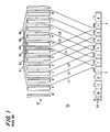
- FIG. 1 shows side pattern coils wound on an armature 50 by one flyer 84 or 87 in a dual flyer winding machine 80 (see FIG. 3).
- FIG. 2 shows the similar coils simultaneously wound on the same armature by the other flyer of the winder. (In all of the drawings like FIGS. 1 and 2 the coils are simplified for greater clarity by omitting the leg of each coil which is closest to commutator 54.)
- coil winding by the first flyer begins by passing the wire from that flyer through the tang on commutator member 1. Then the wire is alternately passed through armature slots A and F until the desired number of turns has been produced in coil b1.
- coil b7 is being wound by the other flyer on the diametrically opposite side of the armature as shown in FIG. 2.
- the wire for coil b7 starts at commutator tang 7 and is wound through slots G and N.
- the wire returns to commutator tang 8, from which the wire is subsequently drawn around slots H and A to produce coil b8 concurrently with the winding of coil b2. Again this process continues until all of coils b7 through b12 have been wound, and winding by the second flyer is concluded by passing the finish lead from coil b12 out through commutator tang 1.
- start and finish leads of each coil run substantially directly to an armature tang which is on the same side of the armature as the coil and which is angularly between the slots on which the coil is wound. Because of this substantially direct routing, the start and finish leads are typically not in contact with the central armature shaft 56 which runs between the core and commutator regions 52 and 54 of the armature (see FIG. 4).
- the later coils deposited by each flyer tend to bear on the leads of the coils deposited earlier by the other flyer. As shown in FIGS.
- coils b10, b11, and b12 wound by the second flyer bear on leads L1, L2, and L3 formed by the first flyer.
- coils b4, b5, and b6 wound by the first flyer bear on leads LR1, LR2, and LR3 formed by the second flyer.
- the coils which thus bear on the leads of other coils tend to be forced radially farther out than previously wound coils. This causes nonuniform distribution of mass around the armature, which can make the armature more difficult to balance.
- the object of the invention is accomplished in accordance with the principles of this invention by providing methods as claimed in claim 1 for winding armatures in which the first several coils are wound so that the start and finish leads of those coils are wrapped around the armature shaft between the core and commutator portions of the armature to an extent sufficient to cause those leads to contact and be supported by the armature shaft. Thereafter, the remaining coils are wound with start and finish leads which are unsupported by the armature shaft.
- FIG. 1 is a simplified planar projection of an illustrative armature showing the conventional side pattern winding of that armature.
- FIG. 2 is similar to FIG. 1 but shows another portion of the conventional side pattern winding of the same armature.
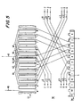
- FIG. 3 is a simplified elevational view of a conventional two-flyer winder which can be used to wind armatures with either the conventional side pattern of FIGS. 1 and 2 or with the modified side pattern of this invention.
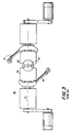
- FIG. 4 is a side elevational view of a portion of an armature wound using the conventional side pattern.
- FIG. 5 is another view similar to FIG. 1 showing a portion of an illustrative embodiment of the modified side pattern of this invention.
- FIG. 6 is still another view similar to FIG. 1 showing another portion of the illustrative embodiment partly shown in FIG. 5.
- FIG. 7 is a simplified sectional view showing one stage of the winding of an armature in accordance with this invention.
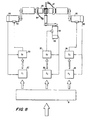
- FIG. 8 is a simplified plan view of illustrative two-flyer winder apparatus with suitable control apparatus shown in block diagram form.
- FIGS. 5 and 6 An illustrative embodiment of modified side pattern armature winding in accordance with this invention is shown in FIGS. 5 and 6.
- this pattern can be produced by a conventional two-flyer winder as shown, for example, in FIG. 3, albeit with the requisite modification of the relative motion of the armature and wire dispensing flyers.
- FIG. 5 shows the windings produced by one flyer
- FIG. 6 shows the windings simultaneously produced by the other flyer.
- winding begins by passing a first coil start lead through commutator tang 1. Armature 50 is then rotated more than 360° about its longitudinal axis to wrap start lead L1 around armature shaft 56 before beginning to wind coil b1 around the chord of the armature which is bounded by slots A and F. Accordingly, start lead L1 contacts and is supported by shaft 56 between core portion 52 and commutator portion 54. When coil b1 is complete, armature 50 is again rotated more than 360° about its longitudinal axis to wrap finish lead L6 around shaft 56 before it reaches commutator tang 2.
- armature 50 is again rotated more than 360° about its longitudinal axis to wrap the start lead L2 for the next coil around shaft 56 before beginning to wind coil b2 around the armature chord between slots B and G.
- the finish lead L5 of coil b2 is also wrapped around shaft 56 by a more than 360° rotation of the armature.
- Lead L5 then passes through commutator tang 3 and becomes the start lead L3 for the next coil b3.
- Start lead L3 is also wrapped around shaft 56 by a more than 360° rotation of the armature, and the finish lead L4 of coil b3 is similarly wrapped around shaft 56 by another more than 360° rotation of the armature.
- FIG. 7 shows how the finish lead L4 of coil b3 is wrapped more than 360° around shaft 56 on its way from slot H to commutator tang 4.
- the later-deposited coils do not bear as much on the start and finish leads for the coils deposited earlier.
- coils b10, b11, and b12 formed by the second flyer do not bear on the start leads L1, L2, and L3 of coils b1 through b3 formed by the first flyer.
- coils b4, b5, and b6 wound by the first flyer do not bear on the start leads LR1 through LR3 of coils b7 through b9 formed by the second flyer. This allows the later-formed coils to be wound closer to armature shaft 56 so that they are more nearly like the preceding coils.
- the fact that the later coils are wound using the side pattern helps reduce the required length of the armature shaft between the core region 52 and the commutator region 54 of the armature, and also allows some air circulation to the ends of the coils adjacent the commutator if that is desired.
- the change from lead routing around the armature shaft is made after making four commutator connections.
- the choice as to when to make this change depends on various armature parameters such as slot pitch, size of the armature, number of coils per slot, diameter of the armature shaft, and the size of the winding wire. In order to make the best choice in this regard, it may be desirable to test several different choices in order to verify by visual inspection the quality of the resulting coils.
- FIGS. 5 and 6 show routing of the leads of the first coils by more than 360° around the armature shaft.
- the angle of wrapping is approximately 360° plus the angle between two and half core slots. Smaller angles of wrapping may be used as long as the leads are supported by the armature shaft. Greater or smaller angles beyond the lines 40 and 42 (slot pitch) shown in FIG. 5 can cause inconvenience when changing to direct lead routing (shown from commutator bar 4 and commutator bar 10 in FIGS. 5 and 6). In particular, for angles beyond the range delimited by these lines, one of the leads going to or from a bar which is directly routed to the core will become excessively long.
- Commutator members for obtaining lead connections according to the principles which have been illustrated in the foregoing are usually of the tang type.
- the leads can be connected to such tangs by well known alpha or omega connections.
- FIGS. 5 and 6 show a particular progression to connect the leads to the commutator bars and to wind the coils in the slots. This progression has been combined with specific turning directions of the flyers. The invention is equally applicable to an opposite progression and also to different turning directions of the flyers.
- a further advantage obtained by winding and lead connecting according to this invention is that the start leads which are wrapped around the armature do not loosen during the winding of the first coils. This avoids the need for extra equipment such as the gripper sleeve used in prior art machines to maintain the wire behind the commutator tangs of the first coils.
- FIG. 8 shows controls for a suitable two-flyer winder.
- computer 81 supplies position commands (i.e., signals indicating the position to be reached by the flyer) to position control cards 82 of motor 83 for driving flyer 84, and also to position control cards 85 of motor 86 for driving flyer 87.
- Computer 81 also supplies position commands to position control cards 88 of motor 101 for indexing the armature in order to position the core slots in relation to wire guides 89.
- Motor 101 also indexes the armature to position the commutator bars so that lead attachment to the same can be obtained by the flyer. Rotation of the armature by motor 101 also produces the desired lead routing between the commutator and the core slots.
- drives 90 control such motor parameters as the acceleration and deceleration ramps and the top speeds of motor 83, 86, and 101.
- the motors are equipped with position sensors 100 to determine the actual position of the flyers during their movements and for determining the position of the armature while it is being indexed. This position information is supplied to the position control cards 82, 85, and 88 and to the drives 90 so that a closed retroactive control is achieved.
- Computer 81 is programmed to produce particular flyer commands and indexing sequences.
- Computer 81 may store this information for each type of armature which is to be processed.
- Illustrative information which may be supplied to computer 81 in order to enable it to calculate the angular position required for indexing the armature to produce a particular winding pattern includes:
- the memory of computer 81 may have to be enlarged as compared to the memory required for conventional winding schemes.
Description
- Theta 1 - angle (or other form of position information) and direction from a zero position of the armature (loading position of the unwound armature) to the first commutator connection where the flyer wire is initially connected (e.g., bars 1 and 7 in FIGS. 5 and 6);
- Theta 2 - angle and direction from the zero position to the slot of the first coil to be wound and to be reached with lead routing wrapped around the armature shaft; and
- Theta 3 - angle and direction for turning the armature corresponding to how many lead attachments must have outgoing leads wrapped around the armature shaft, and which also defines when direct lead routing should start.
Claims (4)
- The method of winding coils (b) of wire on an armature (50) having a longitudinal shaft (56), a plurality of slots (A - N) extending parallel to said shaft and opening radially out from said shaft, said slots being spaced from one another in the circumferential direction around said shaft, and a commutator (54) spaced from said slots along said shaft, said commutator having a plurality of wire anchoring sites (1 - 12) spaced from one another in the circumferential direction around said shaft, each of said coils having a main coil portion which is wrapped around a chord of said armature between two circumferentially spaced slots, a start lead which extends from one of said wire anchoring sites to said main coil portion, and a finish lead which extends from said main coil portion to another of said anchoring sites; wherein said method comprises the step of:winding a first plurality of said coils (b1 - b3, b7 - b9) so that the start and finish leads of each of said first plurality of said coils are wrapped around said shaft to an extent sufficient to cause said start and finish leads of said first plurality of coils to contact said shaft (56); and being characterized in that it further comprises the steps of:winding a second plurality of said coils (b4 - b6, b10 - b12) so that the start and finish leads of each of said second plurality of said coils extend between the associated main coil portion and the associated wire anchoring site (4 -7, 1, 11, 12) without being wrapped around said shaft (56) to such an extent that they contact said shaft (56).
- The method defined in claim 1 wherein said winding steps comprise winding each of said coils so that both of the wire anchoring sites (4,5) associated with each of said coils (b4) are on the same circumferential side of the armature as said chord of said armature around which the main coil portion of said coil is wound.
- The method defined in claim 2 wherein said winding steps comprise winding each of said coils so that both of the wire anchoring sites (4,5) associated with the start and finish leads of each coil (b4) are circumferentially between the two slots defining the chord around which the main coil portion of said coil is wound.
- The method defined in claim 1 wherein two of said coils are wound simultaneously on diametrically opposite sides of said armature.
Applications Claiming Priority (2)
| Application Number | Priority Date | Filing Date | Title |
|---|---|---|---|
| US07/850,957 US5267699A (en) | 1992-03-11 | 1992-03-11 | Methods of winding armatures with modified side pattern |
| US850957 | 1992-03-11 |
Publications (3)
| Publication Number | Publication Date |
|---|---|
| EP0560225A2 EP0560225A2 (en) | 1993-09-15 |
| EP0560225A3 EP0560225A3 (en) | 1995-08-09 |
| EP0560225B1 true EP0560225B1 (en) | 1998-01-07 |
Family
ID=25309563
Family Applications (1)
| Application Number | Title | Priority Date | Filing Date |
|---|---|---|---|
| EP93103557A Expired - Lifetime EP0560225B1 (en) | 1992-03-11 | 1993-03-05 | Methods of winding armatures with modified side pattern |
Country Status (5)
| Country | Link |
|---|---|
| US (1) | US5267699A (en) |
| EP (1) | EP0560225B1 (en) |
| CA (1) | CA2091050C (en) |
| DE (1) | DE69316051T2 (en) |
| ES (1) | ES2112346T3 (en) |
Families Citing this family (8)
| Publication number | Priority date | Publication date | Assignee | Title |
|---|---|---|---|---|
| FR2738413B1 (en) * | 1995-09-04 | 1997-11-28 | Ecia Equip Composants Ind Auto | DIRECT CURRENT ELECTRIC MOTOR AND MANUFACTURING METHOD THEREOF |
| JPH11164533A (en) * | 1997-11-25 | 1999-06-18 | Asmo Co Ltd | Motor, armature and its coil winding method |
| WO2000054395A1 (en) * | 1999-03-09 | 2000-09-14 | Mitsuba Corporation | Winding method for armature and winder |
| KR100373303B1 (en) * | 2000-11-21 | 2003-02-25 | 네오다인코리아 주식회사 | A winding method of stator coil in motor |
| DE102004062813A1 (en) * | 2004-12-27 | 2006-07-06 | Robert Bosch Gmbh | A method for producing the rotor winding of an electrical machine and electrical machine with a rotor winding produced by the method |
| JP5719667B2 (en) * | 2011-04-13 | 2015-05-20 | 株式会社ミツバ | DC motor and winding method |
| JP5719666B2 (en) * | 2011-04-13 | 2015-05-20 | 株式会社ミツバ | DC motor and winding method |
| DE102022101395A1 (en) | 2022-01-21 | 2023-07-27 | Audi Aktiengesellschaft | Needle winding device and needle winding method for producing the pole windings of an FSM rotor |
Family Cites Families (8)
| Publication number | Priority date | Publication date | Assignee | Title |
|---|---|---|---|---|
| US3191269A (en) * | 1958-12-12 | 1965-06-29 | Harry W Moore | Method of winding armatures |
| US3448311A (en) * | 1966-04-25 | 1969-06-03 | Possis Machine Corp | Electrical rotor and method of winding the same |
| US3636621A (en) * | 1966-07-14 | 1972-01-25 | Possis Machine Corp | Lead forming method |
| US3913220A (en) * | 1968-02-09 | 1975-10-21 | Globe Tool Eng Co | Armature winding method |
| US3628229A (en) * | 1969-04-01 | 1971-12-21 | Globe Tool Eng Co | Automatic armature winding machine |
| US3973738A (en) * | 1969-10-15 | 1976-08-10 | The Globe Tool And Engineering Company | Armature winding and leading connecting machine |
| US3972843A (en) * | 1972-11-11 | 1976-08-03 | Chemische Werke Huls Aktiengesellschaft | Expandable styrene polymers suitable for the production of quickly moldable cellular bodies |
| NL8902180A (en) * | 1989-08-29 | 1991-03-18 | Philips Nv | METHOD FOR DEVELOPING AN ANCHOR BODY FROM AN ANCHOR AND ELECTRICAL MACHINE EQUIPPED WITH AN ANCHOR MADE ACCORDING TO THE METHOD |
-
1992
- 1992-03-11 US US07/850,957 patent/US5267699A/en not_active Expired - Fee Related
-
1993
- 1993-03-04 CA CA002091050A patent/CA2091050C/en not_active Expired - Fee Related
- 1993-03-05 ES ES93103557T patent/ES2112346T3/en not_active Expired - Lifetime
- 1993-03-05 EP EP93103557A patent/EP0560225B1/en not_active Expired - Lifetime
- 1993-03-05 DE DE69316051T patent/DE69316051T2/en not_active Expired - Fee Related
Also Published As
| Publication number | Publication date |
|---|---|
| CA2091050A1 (en) | 1993-09-12 |
| EP0560225A3 (en) | 1995-08-09 |
| ES2112346T3 (en) | 1998-04-01 |
| US5267699A (en) | 1993-12-07 |
| DE69316051T2 (en) | 1998-05-14 |
| EP0560225A2 (en) | 1993-09-15 |
| DE69316051D1 (en) | 1998-02-12 |
| CA2091050C (en) | 2003-02-11 |
Similar Documents
| Publication | Publication Date | Title |
|---|---|---|
| US6833648B2 (en) | Sequentially joined-segment coil for rotary electrical machine with high degree of electrical insulation | |
| US3705459A (en) | Wave winding of armatures | |
| EP1852958A2 (en) | Method of forming single-layer coils | |
| CN101411039B (en) | Winding arrangement for rotating electrical machine | |
| US4351102A (en) | Method for winding the stator in a three phase AC machine | |
| JP3904613B2 (en) | Method and apparatus for making wave windings for electrical machines | |
| EP0560225B1 (en) | Methods of winding armatures with modified side pattern | |
| EP1344296B1 (en) | Coil winding arrangement for armatures | |
| US3913220A (en) | Armature winding method | |
| US6910257B1 (en) | Production method of a sequentially joined-segment stator coil of a rotary electrical machine | |
| CA2040609C (en) | Coil winding armatures with parallel coils | |
| JP2004072921A (en) | Method and apparatus for forming coil | |
| JP3691222B2 (en) | Wire twisting prevention device for winding machine | |
| US20040216302A1 (en) | Method of making a two-layer lap winding for a multiphase electrical machine | |
| KR100563393B1 (en) | method and device for producing wave windings for electrical machines | |
| US6062504A (en) | Wire winding guide | |
| USRE27893E (en) | Armature winding and commutator connection | |
| JPH099588A (en) | Method of manufacturing stator of motor | |
| US20060042072A1 (en) | Method of winding stator in motor | |
| US3797105A (en) | Method and apparatus for developing electrical coils | |
| US5232026A (en) | Method and apparatus for the winding of electric machine coils comprising parallel wires | |
| JP3140656B2 (en) | Winding method | |
| US3886653A (en) | Method and apparatus for developing and placing electrical coils | |
| JPH04368454A (en) | Winding apparatus for armature | |
| US6145772A (en) | Device for winding coils in axial grooves of rotationally symmetrical bodies of electric equipment |
Legal Events
| Date | Code | Title | Description |
|---|---|---|---|
| PUAI | Public reference made under article 153(3) epc to a published international application that has entered the european phase |
Free format text: ORIGINAL CODE: 0009012 |
|
| AK | Designated contracting states |
Kind code of ref document: A2 Designated state(s): CH DE ES FR GB IT LI NL SE |
|
| PUAL | Search report despatched |
Free format text: ORIGINAL CODE: 0009013 |
|
| AK | Designated contracting states |
Kind code of ref document: A3 Designated state(s): CH DE ES FR GB IT LI NL SE |
|
| 17P | Request for examination filed |
Effective date: 19960209 |
|
| 17Q | First examination report despatched |
Effective date: 19960617 |
|
| GRAG | Despatch of communication of intention to grant |
Free format text: ORIGINAL CODE: EPIDOS AGRA |
|
| GRAG | Despatch of communication of intention to grant |
Free format text: ORIGINAL CODE: EPIDOS AGRA |
|
| GRAH | Despatch of communication of intention to grant a patent |
Free format text: ORIGINAL CODE: EPIDOS IGRA |
|
| GRAH | Despatch of communication of intention to grant a patent |
Free format text: ORIGINAL CODE: EPIDOS IGRA |
|
| GRAA | (expected) grant |
Free format text: ORIGINAL CODE: 0009210 |
|
| AK | Designated contracting states |
Kind code of ref document: B1 Designated state(s): CH DE ES FR GB IT LI NL SE |
|
| PG25 | Lapsed in a contracting state [announced via postgrant information from national office to epo] |
Ref country code: NL Free format text: LAPSE BECAUSE OF FAILURE TO SUBMIT A TRANSLATION OF THE DESCRIPTION OR TO PAY THE FEE WITHIN THE PRESCRIBED TIME-LIMIT Effective date: 19980107 |
|
| REG | Reference to a national code |
Ref country code: CH Ref legal event code: EP |
|
| REF | Corresponds to: |
Ref document number: 69316051 Country of ref document: DE Date of ref document: 19980212 |
|
| REG | Reference to a national code |
Ref country code: CH Ref legal event code: NV Representative=s name: ROTTMANN, ZIMMERMANN + PARTNER AG |
|
| ITF | It: translation for a ep patent filed |
Owner name: BARZANO'E ZANARDO S.P.A. |
|
| REG | Reference to a national code |
Ref country code: ES Ref legal event code: FG2A Ref document number: 2112346 Country of ref document: ES Kind code of ref document: T3 |
|
| PG25 | Lapsed in a contracting state [announced via postgrant information from national office to epo] |
Ref country code: SE Free format text: LAPSE BECAUSE OF FAILURE TO SUBMIT A TRANSLATION OF THE DESCRIPTION OR TO PAY THE FEE WITHIN THE PRESCRIBED TIME-LIMIT Effective date: 19980407 |
|
| ET | Fr: translation filed | ||
| NLV1 | Nl: lapsed or annulled due to failure to fulfill the requirements of art. 29p and 29m of the patents act | ||
| PLBE | No opposition filed within time limit |
Free format text: ORIGINAL CODE: 0009261 |
|
| STAA | Information on the status of an ep patent application or granted ep patent |
Free format text: STATUS: NO OPPOSITION FILED WITHIN TIME LIMIT |
|
| 26N | No opposition filed | ||
| REG | Reference to a national code |
Ref country code: GB Ref legal event code: IF02 |
|
| PGFP | Annual fee paid to national office [announced via postgrant information from national office to epo] |
Ref country code: GB Payment date: 20050223 Year of fee payment: 13 |
|
| PG25 | Lapsed in a contracting state [announced via postgrant information from national office to epo] |
Ref country code: GB Free format text: LAPSE BECAUSE OF NON-PAYMENT OF DUE FEES Effective date: 20060305 |
|
| PGFP | Annual fee paid to national office [announced via postgrant information from national office to epo] |
Ref country code: IT Payment date: 20060331 Year of fee payment: 14 |
|
| GBPC | Gb: european patent ceased through non-payment of renewal fee |
Effective date: 20060305 |
|
| PGFP | Annual fee paid to national office [announced via postgrant information from national office to epo] |
Ref country code: ES Payment date: 20080326 Year of fee payment: 16 Ref country code: CH Payment date: 20080320 Year of fee payment: 16 |
|
| PGFP | Annual fee paid to national office [announced via postgrant information from national office to epo] |
Ref country code: FR Payment date: 20080314 Year of fee payment: 16 Ref country code: DE Payment date: 20080521 Year of fee payment: 16 |
|
| PG25 | Lapsed in a contracting state [announced via postgrant information from national office to epo] |
Ref country code: IT Free format text: LAPSE BECAUSE OF NON-PAYMENT OF DUE FEES Effective date: 20070305 |
|
| REG | Reference to a national code |
Ref country code: CH Ref legal event code: PL |
|
| REG | Reference to a national code |
Ref country code: FR Ref legal event code: ST Effective date: 20091130 |
|
| PG25 | Lapsed in a contracting state [announced via postgrant information from national office to epo] |
Ref country code: LI Free format text: LAPSE BECAUSE OF NON-PAYMENT OF DUE FEES Effective date: 20090331 Ref country code: DE Free format text: LAPSE BECAUSE OF NON-PAYMENT OF DUE FEES Effective date: 20091001 Ref country code: CH Free format text: LAPSE BECAUSE OF NON-PAYMENT OF DUE FEES Effective date: 20090331 |
|
| PG25 | Lapsed in a contracting state [announced via postgrant information from national office to epo] |
Ref country code: FR Free format text: LAPSE BECAUSE OF NON-PAYMENT OF DUE FEES Effective date: 20091123 |
|
| REG | Reference to a national code |
Ref country code: ES Ref legal event code: FD2A Effective date: 20090306 |
|
| PG25 | Lapsed in a contracting state [announced via postgrant information from national office to epo] |
Ref country code: ES Free format text: LAPSE BECAUSE OF NON-PAYMENT OF DUE FEES Effective date: 20090306 |