EP0560042B1 - Feeding device of an angle shears with rotary cutters - Google Patents
Feeding device of an angle shears with rotary cutters Download PDFInfo
- Publication number
- EP0560042B1 EP0560042B1 EP93101568A EP93101568A EP0560042B1 EP 0560042 B1 EP0560042 B1 EP 0560042B1 EP 93101568 A EP93101568 A EP 93101568A EP 93101568 A EP93101568 A EP 93101568A EP 0560042 B1 EP0560042 B1 EP 0560042B1
- Authority
- EP
- European Patent Office
- Prior art keywords
- sheet metal
- pair
- feed unit
- unit according
- surface elements
- Prior art date
- Legal status (The legal status is an assumption and is not a legal conclusion. Google has not performed a legal analysis and makes no representation as to the accuracy of the status listed.)
- Expired - Lifetime
Links
Images


Classifications
-
- B—PERFORMING OPERATIONS; TRANSPORTING
- B26—HAND CUTTING TOOLS; CUTTING; SEVERING
- B26D—CUTTING; DETAILS COMMON TO MACHINES FOR PERFORATING, PUNCHING, CUTTING-OUT, STAMPING-OUT OR SEVERING
- B26D1/00—Cutting through work characterised by the nature or movement of the cutting member or particular materials not otherwise provided for; Apparatus or machines therefor; Cutting members therefor
-
- B—PERFORMING OPERATIONS; TRANSPORTING
- B21—MECHANICAL METAL-WORKING WITHOUT ESSENTIALLY REMOVING MATERIAL; PUNCHING METAL
- B21D—WORKING OR PROCESSING OF SHEET METAL OR METAL TUBES, RODS OR PROFILES WITHOUT ESSENTIALLY REMOVING MATERIAL; PUNCHING METAL
- B21D43/00—Feeding, positioning or storing devices combined with, or arranged in, or specially adapted for use in connection with, apparatus for working or processing sheet metal, metal tubes or metal profiles; Associations therewith of cutting devices
- B21D43/28—Associations of cutting devices therewith
- B21D43/287—Devices for handling sheet or strip material
-
- B—PERFORMING OPERATIONS; TRANSPORTING
- B65—CONVEYING; PACKING; STORING; HANDLING THIN OR FILAMENTARY MATERIAL
- B65G—TRANSPORT OR STORAGE DEVICES, e.g. CONVEYORS FOR LOADING OR TIPPING, SHOP CONVEYOR SYSTEMS OR PNEUMATIC TUBE CONVEYORS
- B65G47/00—Article or material-handling devices associated with conveyors; Methods employing such devices
- B65G47/22—Devices influencing the relative position or the attitude of articles during transit by conveyors
- B65G47/26—Devices influencing the relative position or the attitude of articles during transit by conveyors arranging the articles, e.g. varying spacing between individual articles
- B65G47/261—Accumulating articles
- B65G47/268—Accumulating articles by means of belt or chain conveyor
-
- Y—GENERAL TAGGING OF NEW TECHNOLOGICAL DEVELOPMENTS; GENERAL TAGGING OF CROSS-SECTIONAL TECHNOLOGIES SPANNING OVER SEVERAL SECTIONS OF THE IPC; TECHNICAL SUBJECTS COVERED BY FORMER USPC CROSS-REFERENCE ART COLLECTIONS [XRACs] AND DIGESTS
- Y10—TECHNICAL SUBJECTS COVERED BY FORMER USPC
- Y10T—TECHNICAL SUBJECTS COVERED BY FORMER US CLASSIFICATION
- Y10T83/00—Cutting
- Y10T83/202—With product handling means
- Y10T83/2092—Means to move, guide, or permit free fall or flight of product
- Y10T83/2192—Endless conveyor
-
- Y—GENERAL TAGGING OF NEW TECHNOLOGICAL DEVELOPMENTS; GENERAL TAGGING OF CROSS-SECTIONAL TECHNOLOGIES SPANNING OVER SEVERAL SECTIONS OF THE IPC; TECHNICAL SUBJECTS COVERED BY FORMER USPC CROSS-REFERENCE ART COLLECTIONS [XRACs] AND DIGESTS
- Y10—TECHNICAL SUBJECTS COVERED BY FORMER USPC
- Y10T—TECHNICAL SUBJECTS COVERED BY FORMER US CLASSIFICATION
- Y10T83/00—Cutting
- Y10T83/647—With means to convey work relative to tool station
- Y10T83/6476—Including means to move work from one tool station to another
- Y10T83/6478—Tool stations angularly related
- Y10T83/648—Work manipulated between tool stations
-
- Y—GENERAL TAGGING OF NEW TECHNOLOGICAL DEVELOPMENTS; GENERAL TAGGING OF CROSS-SECTIONAL TECHNOLOGIES SPANNING OVER SEVERAL SECTIONS OF THE IPC; TECHNICAL SUBJECTS COVERED BY FORMER USPC CROSS-REFERENCE ART COLLECTIONS [XRACs] AND DIGESTS
- Y10—TECHNICAL SUBJECTS COVERED BY FORMER USPC
- Y10T—TECHNICAL SUBJECTS COVERED BY FORMER US CLASSIFICATION
- Y10T83/00—Cutting
- Y10T83/647—With means to convey work relative to tool station
- Y10T83/6476—Including means to move work from one tool station to another
- Y10T83/6489—Slitter station
-
- Y—GENERAL TAGGING OF NEW TECHNOLOGICAL DEVELOPMENTS; GENERAL TAGGING OF CROSS-SECTIONAL TECHNOLOGIES SPANNING OVER SEVERAL SECTIONS OF THE IPC; TECHNICAL SUBJECTS COVERED BY FORMER USPC CROSS-REFERENCE ART COLLECTIONS [XRACs] AND DIGESTS
- Y10—TECHNICAL SUBJECTS COVERED BY FORMER USPC
- Y10T—TECHNICAL SUBJECTS COVERED BY FORMER US CLASSIFICATION
- Y10T83/00—Cutting
- Y10T83/647—With means to convey work relative to tool station
- Y10T83/654—With work-constraining means on work conveyor [i.e., "work-carrier"]
-
- Y—GENERAL TAGGING OF NEW TECHNOLOGICAL DEVELOPMENTS; GENERAL TAGGING OF CROSS-SECTIONAL TECHNOLOGIES SPANNING OVER SEVERAL SECTIONS OF THE IPC; TECHNICAL SUBJECTS COVERED BY FORMER USPC CROSS-REFERENCE ART COLLECTIONS [XRACs] AND DIGESTS
- Y10—TECHNICAL SUBJECTS COVERED BY FORMER USPC
- Y10T—TECHNICAL SUBJECTS COVERED BY FORMER US CLASSIFICATION
- Y10T83/00—Cutting
- Y10T83/647—With means to convey work relative to tool station
- Y10T83/6584—Cut made parallel to direction of and during work movement
- Y10T83/6633—By work moving flexible chain or conveyor
Definitions
- the invention relates to a feed device for sheet metal strips made of ferromagnetic material for the second pair of knife shafts of a roller knife angle scissors with a rest for the sheet metal strips cut by the first pair of knife shafts and at least one rotating driver element.
- Roller knife angle scissors have two pairs of knife shafts with roller knives.
- the axes of each pair of knife shafts are - viewed in plan view - perpendicular to the axes of the other pair of knife shafts (see e.g. EP 0 208 564 A1).
- sheets of metal, in particular tinplate for sheet metal packaging are cut into strips and placed on a storage and transport table lying behind the first pair of knife shafts, viewed in the feed direction, with virtually no spacing from one another. There, the strips must be separated and fed individually to the second pair of knife shafts at right angles to the direction of advance of the first pair of knife shafts.
- two solutions are known for separating the strips and feeding them to the second pair of knife shafts.
- the storage for the sheet metal strips is designed in a step-like or terrace-shaped manner, for example by plates of different heights, towards the second pair of knife shafts, each Strip is assigned its own level.
- the revolving driver element usually consists of two chains, the driver pawls - the same on the left and right - are designed differently according to the different storage levels. Along the course of the chains, the distance between the driver pawls is greater than the step length or the strip width, so that the strips are transported one after the other - separated from one another - to the second pair of knife shafts.
- a disadvantage of this feed device is that the driver pawls on the chain and the step plates have to be adjusted or even exchanged when changing the format (different strip width and possibly number), which leads to undesirable downtimes of the angle shears.
- the driver pawls hit the resting strips at a constant speed. There is therefore a risk of the rear edge of the strips being damaged by an impact. Otherwise, the individual strips cut from a board are subject to different fall conditions (different fall height and thus different fall times).
- rotatable rods are located above the transport plane for the second pair of knife shafts, with one rod being assigned to each strip.
- the strips are pushed onto the rods by the first pair of knife shafts and the rods are rotated one after the other so that the strips fall individually onto the transport plane for the second pair of knife shafts.
- Circulating chains with mechanical, form-fitting driver pawls advance the strips separated in this way to the second pair of knife shafts.
- the invention has for its object to improve a feed device of the type mentioned with simple means to the effect that the format change of the strips can be carried out quickly and easily.
- the tray for the sheet metal strips consists of flat surface elements with a smooth surface, which are separated from each other by a parallel distance running in the direction of feed, that the circumferential driving element is designed as an endless belt, the upper strand between which or between two surface elements by a distance of 0.1 to 0.9 mm, preferably 0.2 to 0.5 mm, is arranged below the storage and transport plane formed by the surface elements and that a plurality of below the upper strand of the endless belt successively arranged, individually controllable magnet arrangements are available.
- the feed device according to the invention has a storage and transport plane for the sheet metal strips that is completely open at the top and therefore easily accessible. It consists only of simple parts, the movement of which poses no danger during operation. When changing the format, no mechanical parts are replaced and only mechanical parts (Stop bar and possibly the feed table) which does not cause any problems due to the good accessibility, and all that is required is a different control of the change in height of the magnet arrangements located under the upper run.
- the feed device according to the invention is finally suitable for high performance, since no damage is possible due to the frictional connection between the circulating endless belt and the metal strip.
- these can be constructed from a plurality of individual magnets which are arranged - also one above the other - in two rows, each separated by a distance running in the direction of the endless belt.
- the mutually facing edges of the or two adjacent surface elements are angled downwards and the upper run of the endless belt is arranged with its edges on the angled edges.
- the height adjustment of the magnet arrangements is preferably accomplished by pneumatic lifting cylinders.
- the feed device has a feed table 1 with a storage and transport plane 2 for ferromagnetic sheet metal strips S.1 to S.3 (generally S.1 to S.n).
- the feed table 1 is arranged underneath a first pair of knife shafts 3 with roller knives 4, through which sheet metal sheets reach another transport level 5 (top right in FIG. 1) and are cut into strips.
- the strips leave the pair of knife shafts 3 in the direction of the feed table 1 and are positioned in their rest position by an adjustable stop bar 6 running parallel to the pair of knife shafts 3.
- the storage or transport plane 2 is formed by two plates 7, 7 'running parallel to the pair of knife shafts 3 and made of wear-resistant, non-rusting material with a smooth surface, between which there is a parallel distance or gap 8 (see FIG. 4).
- the edge regions of the sheets 7, 7 'forming the gap 8 are angled slightly downwards.
- the stop bar 6 is detachably fastened for adjustment.
- the upper run 9 runs inside the gap 8 and consists of a flat belt formed endless belt 10.
- the upper run 9 lies with its lateral edges on the angled edge regions of the sheets 7, 7 ', and its surface is a few tenths of a millimeter (see dimension a in FIG. 5) below the transport plane 2.
- the endless belt 10 is deflected around a first deflection roller 12 immediately before a second pair of knife shafts 11. Below the deflection roller 12 there is - in the middle - another deflection roller 13 and - below - a drive roller 14 which holds the lower strand 15 of the endless belt 10.
- the axes of the rollers 12 to 14 are essentially perpendicular to one another, so that there is a remarkable angle of wrap around the drive roller 14 of almost 180 ° for the endless belt 10.
- the endless belt 10 is redirected at the end of the feed table 1 facing away from the pair of knife shafts 11 by a roller arrangement 16 corresponding to the rollers 12 to 14 from the lower strand 15 into the upper strand 9.
- the roller assembly 16 can serve as a whole for tensioning the endless belt 10, but only one, e.g. the middle roller of the roller arrangement 16 or a further roller (not shown) can be used for tensioning the endless belt.
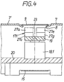
- the magnet arrangements 17.i can be formed in one piece (as shown in FIGS. 1 and 2 for 17.i) or be composed of a plurality of magnet elements aligned with the same polarity. 2 and 4, the magnet arrangement 17.1 is shown as consisting of eight individual magnets 27a to 27h.
- the individual magnets 27a to 27d lie - as seen in the direction of section IV-IV - in a left row, the individual magnets 27e to 27h in a right row on a magnet holder 19 connected to the adjusting member 18.1 (generally: 18.i) (the individual magnets 27f and 27h are shown in FIG. 2 by the individual magnets 27b and 27d and in FIG. 4 by the individual magnets 27e and 27g) and are separated by a gap 23.
- the adjusting members 18.i are designed as individually controllable pneumatic lifting cylinders and fastened on a common carrier or holder 20.
- the entire feed table 1 can be adjusted in a horizontal direction perpendicular to the axes of the first pair of knife shafts 3.
- the adjusting members 18.i can also be designed as hydraulic cylinders or electric lifting magnets.
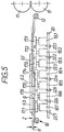
- the separation process of the strips S.1 to S.3 is explained in more detail with reference to FIG. 5.
- the strips S.1 to S.3 are cut by the round knives 4 of the pair of knife shafts 3 on a sheet of tinplate and lie side by side on the storage or transport level 2.
- the valves 22.1 to 22.3 are switched, see above that the magnet arrangements 17.1 to 17.3 are raised.
- the upper run 9 of the endless belt 10 which lies before the activation of the valves 22.1 to 22.3 by a dimension a of a few tenths of a millimeter below the transport plane 2, is pushed upwards by the magnets 17.1 to 17.3 in its area so that the surface of the upper run 9 lies at the level of transport level 2. Due to the pressure of the pneumatic cylinders 18.1 to 18.3, the upper run 9 is brought into close contact with the sheet metal strips S.1 in the raised position. The magnets 17.1 to 17.3 also exert an attractive force on the sheet metal strip S.1, so that a frictional engagement occurs between the upper run 9 and the sheet metal strip S.1 and the sheet metal strip is carried along by the endless belt 10 in the direction of the pair of knife shafts 11. The sheet metal strip S.1 is cut into blanks by the roller knives of the pair of knife shafts 11.
- the valves 22.4 and 22.5 are additionally activated and the magnet arrangements 17.4, 17.5 are raised, so that the sheet metal strip S.2 is taken from the endless belt 10.
- the valves 22.6 and 22.7 are also activated and the sheet metal strip S.3 by lifting the magnet arrangements 17.6 and 17.7 taken in the direction of the pair of knife shafts 11.
- all valves 22.i are switched back. All of the magnet arrangements 17.i are lowered, and the upper run 9 of the endless belt 10 is now again below the transport plane 2, and the transport table 1 is prepared for depositing a further set of sheet metal strips.
- the feed table 101 is provided with two endless belts 110 and 210, each between the sheets 107, 107 'and 107' 'forming the storage and transport plane 102. are arranged, equipped.
- the structure of the endless belts 110, 210 with the associated magnet arrangements 117.i and 217.i and the associated adjusting members 118.i and 218.i corresponds to the structure of the endless belt 10.
- a longitudinal section through each of the endless belts 110 and 210 corresponds to the longitudinal section by the endless belt 10 according to FIG. 2.
- the magnet arrangements 117.i and 217.i which are each at the same distance from the knife shaft pair 11, for example 117.1 and 217.1, raised or lowered simultaneously.
- the sheet metal strips are always recorded in two points at the same time and transported safely without the risk of jamming.
Description
Die Erfindung betrifft eine Vorschubeinrichtung für Blechstreifen aus ferromagnetischem Material zu dem zweiten Messerwellenpaar einer Rollenmesserwinkelschere mit einer Ablage für die von dem ersten Messerwellenpaar geschnittenen Blechstreifen und mindestens einem umlaufenden Mitnehmerorgan.The invention relates to a feed device for sheet metal strips made of ferromagnetic material for the second pair of knife shafts of a roller knife angle scissors with a rest for the sheet metal strips cut by the first pair of knife shafts and at least one rotating driver element.
Rollenmesserwinkelscheren weisen zwei Messerwellenpaare mit Rollenmessern auf. Die Achsen jedes Messerwellenpaares sind - in der Draufsicht gesehen - senkrecht zu den Achsen des anderen Messerwellenpaares angeordnet (vgl. z.B. EP 0 208 564 A1). Mit dem ersten Messerwellenpaar werden Blechtafeln, insbesondere aus Weißblech für Blechverpackungen, in Streifen geschnitten und auf einen, in Vorschubrichtung gesehen, hinter dem ersten Messerwellenpaar liegenden Ablage- und Transporttisch praktisch ohne Abstand zueinander abgelegt. Dort müssen die Streifen separiert und einzeln rechtwinklig zur Vorschubrichtung des ersten Messerwellenpaares dem zweiten Messerwellenpaar zugeführt werden. Für das Separieren der Streifen und ihr Zuführen zum zweiten Messerwellenpaar sind im wesentlichen zwei Lösungen bekannt.Roller knife angle scissors have two pairs of knife shafts with roller knives. The axes of each pair of knife shafts are - viewed in plan view - perpendicular to the axes of the other pair of knife shafts (see e.g. EP 0 208 564 A1). With the first pair of knife shafts, sheets of metal, in particular tinplate for sheet metal packaging, are cut into strips and placed on a storage and transport table lying behind the first pair of knife shafts, viewed in the feed direction, with virtually no spacing from one another. There, the strips must be separated and fed individually to the second pair of knife shafts at right angles to the direction of advance of the first pair of knife shafts. Essentially two solutions are known for separating the strips and feeding them to the second pair of knife shafts.
Bei einer gattungsgemäßen Vorschubeinrichtung ist die Ablage für die Blechstreifen z.B. durch verschieden hohe Platten stufen- bzw. terrassenförmig zum zweiten Messerwellenpaar hin abnehmend ausgebildet, wobei jedem Streifen eine eigene Stufe zugeordnet ist. Das umlaufende Mitnehmerorgan besteht in der Regel aus zwei Ketten, deren Mitnehmerklinken - links und rechts gleich - den verschiedenen Ablagestufen entsprechend unterschiedlich hoch ausgebildet sind. Entlang dem Verlauf der Ketten ist der Abstand der Mitnehmerklinken größer als die Stufenlänge bzw. die Streifenbreite, so daß die Streifen nacheinander - voneinander separiert - zum zweiten Messerwellenpaar transportiert werden.In the case of a generic feed device, the storage for the sheet metal strips is designed in a step-like or terrace-shaped manner, for example by plates of different heights, towards the second pair of knife shafts, each Strip is assigned its own level. The revolving driver element usually consists of two chains, the driver pawls - the same on the left and right - are designed differently according to the different storage levels. Along the course of the chains, the distance between the driver pawls is greater than the step length or the strip width, so that the strips are transported one after the other - separated from one another - to the second pair of knife shafts.
Nachteilig bei dieser Vorschubeinrichtung ist, daß die Mitnehmerklinken auf der Kette und die Stufenplatten bei einem Formatwechsel (andere Streifenbreite und ggf. Anzahl) verstellt bzw. sogar ausgewechselt werden müssen, was zu unerwünschten Stillstandszeiten der Winkelschere führt. Die Mitnehmerklinken treffen mit konstanter Geschwindigkeit auf die ruhenden Streifen. Es besteht somit die Gefahr einer Beschädigung der hinteren Kante der Streifen durch einen Einschlag. Im übrigen unterliegen die einzelnen, aus einer Tafel geschnittenen Streifen verschiedenen Fallbedingungen (unterschiedliche Fallhöhe und damit unterschiedliche Fallzeiten).A disadvantage of this feed device is that the driver pawls on the chain and the step plates have to be adjusted or even exchanged when changing the format (different strip width and possibly number), which leads to undesirable downtimes of the angle shears. The driver pawls hit the resting strips at a constant speed. There is therefore a risk of the rear edge of the strips being damaged by an impact. Otherwise, the individual strips cut from a board are subject to different fall conditions (different fall height and thus different fall times).
Bei einer anderen bekannten Vorschubeinrichtung befinden sich oberhalb der Transportebene für das zweite Messerwellenpaar drehbare Stangen, wobei jedem Streifen eine Stange zugeordnet ist. Die Streifen werden von dem ersten Messerwellenpaar auf die Stangen geschoben und die Stangen nacheinander gedreht, so daß die Streifen einzeln auf die Transportebene für das zweite Messerwellenpaar fallen. Umlaufende Ketten mit mechanischen, formschlüssigen Mitnehmerklinken schieben die derart separierten Streifen zum zweiten Messerwellenpaar vor.In another known feed device, rotatable rods are located above the transport plane for the second pair of knife shafts, with one rod being assigned to each strip. The strips are pushed onto the rods by the first pair of knife shafts and the rods are rotated one after the other so that the strips fall individually onto the transport plane for the second pair of knife shafts. Circulating chains with mechanical, form-fitting driver pawls advance the strips separated in this way to the second pair of knife shafts.
Auch bei dieser Vorschubeinrichtung sind bei einem Formatwechsel der Streifen umfangreiche Umrüstungen notwendig. Außerdem ist die Transportebene zum zweiten Messerwellenpaar von oben verbaut. Dies ist hinderlich bei der Beseitigung von sog. Stoppern (Stillstände infolge unbeabsichtigter Ereignisse). Zum Steuern der Wendestangen ist eine aufwendige Getriebeanordnung notwendig, und es besteht ebenfalls die Gefahr von Einschlägen der Mitnehmerklinken in die hintere Kante der Blechstreifen. Bei einem Formatwechsel der Blechstreifen ist ein erheblicher Aufwand zum Umrichten notwendig.With this feed device, too, extensive changes are made to the strips when the format is changed necessary. In addition, the transport level to the second pair of knife shafts is installed from above. This is a hindrance when eliminating so-called stoppers (downtimes due to unintended events). A complex gear arrangement is necessary to control the turning bars, and there is also the risk of the driver pawls striking the rear edge of the sheet metal strips. When changing the format of the sheet metal strips, considerable effort is required for the conversion.
Der Erfindung liegt die Aufgabe zugrunde, eine Vorschubeinrichtung der eingangs genannten Art mit einfachen Mitteln dahingehend zu verbessern, daß ein Formatwechsel der Streifen ohne großen Aufwand und schnell vollzogen werden kann.The invention has for its object to improve a feed device of the type mentioned with simple means to the effect that the format change of the strips can be carried out quickly and easily.
Diese Aufgabe wird dadurch gelöst, daß die Ablage für die Blechstreifen aus ebenen Flächenelementen mit glatter Oberfläche besteht, die bzw. die jeweils durch einen in Vorschubrichtung verlaufenden, parallen Abstand voneinander getrennt sind, daß das umlaufende Mitnehmerorgan als Endlosband ausgebildet ist, dessen Obertrum zwischen den bzw. zwischen zwei Flächenelementen um einen Abstand von 0,1 bis 0,9 mm, vorzugsweise 0,2 bis 0,5 mm, unterhalb der durch die Flächenelemente gebildeten Ablage- und Transportebene angeordnet ist und daß unterhalb des Obertrum des Endlosbandes eine Vielzahl von hintereinander angeordneten, in der Höhe einzeln steuerbaren Magnetanordnungen vorhanden sind.This object is achieved in that the tray for the sheet metal strips consists of flat surface elements with a smooth surface, which are separated from each other by a parallel distance running in the direction of feed, that the circumferential driving element is designed as an endless belt, the upper strand between which or between two surface elements by a distance of 0.1 to 0.9 mm, preferably 0.2 to 0.5 mm, is arranged below the storage and transport plane formed by the surface elements and that a plurality of below the upper strand of the endless belt successively arranged, individually controllable magnet arrangements are available.
Die erfindungsgemäße Vorschubeinrichtung weist eine nach oben hin völlig offene und dadurch gut zugängliche Ablage- und Transportebene für die Blechstreifen auf. Sie besteht lediglich aus einfachen Teilen, deren Bewegung beim Betrieb keinerlei Gefahr nach sich zieht. Bei einem Formatwechsel werden keine mechanischen Teile ausgewechselt, und es werden lediglich mechanische Teile (Anschlagleiste und ggf. der Vorschubtisch) verstellt, was bei der guten Zugänglichkeit keinerlei Probleme bereitet, und es bedarf lediglich einer anderen Ansteuerung der Höhenveränderung der unter dem Obertrum befindlichen Magnetanordnungen. Die erfindungsgemäße Vorschubeinrichtung ist schließlich für hohe Leistung geeignet, da durch den Reibschluß zwischen dem umlaufenden Endlosband und dem Blechstreifen keine Beschädigung möglich ist.The feed device according to the invention has a storage and transport plane for the sheet metal strips that is completely open at the top and therefore easily accessible. It consists only of simple parts, the movement of which poses no danger during operation. When changing the format, no mechanical parts are replaced and only mechanical parts (Stop bar and possibly the feed table) which does not cause any problems due to the good accessibility, and all that is required is a different control of the change in height of the magnet arrangements located under the upper run. The feed device according to the invention is finally suitable for high performance, since no damage is possible due to the frictional connection between the circulating endless belt and the metal strip.
Um die Magnetwirkung der Magnetanordnungen zu erhöhen, können diese aus mehreren Einzelmagneten aufgebaut sein, die - auch übereinander - in zwei Reihen angeordnet sind, die jeweils durch einen in Richtung des Endlosbandes verlaufenden Abstand voneinander getrennt sind.In order to increase the magnetic effect of the magnet arrangements, these can be constructed from a plurality of individual magnets which are arranged - also one above the other - in two rows, each separated by a distance running in the direction of the endless belt.
Um einen betriebssicheren Lauf des Endlosbandes zu erreichen und eine eindeutige Höhenlage desselben vorgeben zu können, sind die einander zugewandten Kanten der bzw. zweier benachbarter Flächenelemente nach unten abgewinkelt und das Obertrum des Endlosbandes mit seinen Kanten auf den abgewinkelten Kanten angeordnet.In order to achieve reliable operation of the endless belt and to be able to specify a clear altitude, the mutually facing edges of the or two adjacent surface elements are angled downwards and the upper run of the endless belt is arranged with its edges on the angled edges.
Die Höhenverstellung der Magnetanordnungen wird vorzugsweise durch pneumatische Hubzylinder bewerkstelligt.The height adjustment of the magnet arrangements is preferably accomplished by pneumatic lifting cylinders.
Ausführungsbeispiele der Erfindung sind in der Zeichnung dargestellt und werden im folgenden näher erläutert. Es zeigen
- Fig. 1
- eine Vorschubeinrichtung in einem Querschnitt,
- Fig. 2
- die Vorschubeinrichtung in einem Längsschnitt längs der Linie II-II in Fig. 1,
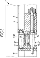
- Fig. 3
- die Vorschubeinrichtung in einem auszugsweisen Querschnitt längs der Linie III-III in Fig. 2,
- Fig. 4
- die Vorschubeinrichtung in einem auszugsweisen Querschnitt längs der Linie IV-IV in Fig. 2,
- Fig. 5
- die Vorschubeinrichtung in einem auszugsweisen schematisierten Längsschnitt während des Separierens des ersten Blechstreifens und
- Fig. 6
- eine Vorschubeinrichtung mit zwei umlaufenden Endlosbändern im Querschnitt.
- Fig. 1
- a feed device in a cross section,
- Fig. 2
- the feed device in a longitudinal section along the line II-II in Fig. 1,
- Fig. 3
- the feed device in a partial cross-section along the line III-III in Fig. 2,
- Fig. 4
- the feed device in a partial cross-section along the line IV-IV in Fig. 2,
- Fig. 5
- the feed device in a partial schematic longitudinal section during the separation of the first sheet metal strip and
- Fig. 6
- a feed device with two circulating endless belts in cross section.
Die Vorschubeinrichtung gemäß den Fig. 1 bis 5 weist einen Vorschubtisch 1 mit einer Ablage- und Transportebene 2 für ferromagnetische Blechstreifen S.1 bis S.3 (allgemein S.1 bis S.n) auf. Der Vorschubtisch 1 ist unterhalb eines ersten Messerwellenpaares 3 mit Rollenmessern 4 angeordnet, durch die Blechtafeln in Höhe einer anderen Transportebene 5 (in Fig. 1 oben rechts) gelangen und zu Streifen geschnitten werden. Die Streifen verlassen das Messerwellenpaar 3 in Richtung des Vorschubtisches 1 und werden durch eine parallel zu dem Messerwellenpaar 3 verlaufende, verstellbare Anschlagleiste 6 in ihrer Ruhelage positioniert.The feed device according to FIGS. 1 to 5 has a feed table 1 with a storage and
Die Ablage- bzw. Transportebene 2 wird durch zwei parallele zum Messerwellenpaar 3 verlaufende Bleche 7, 7' aus verschleißfestem, nichtrostendem Material mit glatter Oberfläche gebildet, zwischen denen ein paralleler Abstand oder Spalt 8 (vgl. Fig. 4) besteht. Die den Spalt 8 bildenden Kantenbereiche der Bleche 7, 7' sind etwas nach unten abgewinkelt. An dem von dem Messerwellenpaar 3 abgewandten Blech 7 ist die Anschlagleiste 6 zum Verstellen lösbar befestigt.The storage or
Zwischen den beiden Blechen 7, 7' verläuft innerhalb des Spaltes 8 das Obertrum 9 eines aus einem Flachriemen gebildeten Endlosbandes 10. Das Obertrum 9 liegt mit seinen seitlichen Kanten auf den abgewinkelten Kantenbereichen der Bleche 7, 7' auf, und seine Oberfläche liegt dabei wenige Zehntelmillimeter (vgl. Maß a in Fig. 5) unter der Transportebene 2.Between the two
Das Endlosband 10 wird unmittelbar vor einem zweiten Messerwellenpaar 11 um eine erste Umlenkrolle 12 umgelenkt. Unterhalb der Umlenkrolle 12 befindet sich - mittig - eine weitere Umlenkrolle 13 und - unten - eine Antriebsrolle 14, die das Untertrum 15 des Endlosbandes 10 hält. Die Achsen der Rollen 12 bis 14 stehen im wesentlichen senkrecht untereinander, so daß sich für das Endlosband 10 ein bemerkenswerter Umschlingungswinkel um die Antriebsrolle 14 von fast 180° ergibt.The
Das Endlosband 10 wird an dem von dem Messerwellenpaar 11 abgewandten Ende des Vorschubtisches 1 von einer den Rollen 12 bis 14 entsprechenden Rollenanordnung 16 vom Untertrum 15 in das Obertrum 9 erneut umgelenkt. Die Rollenanordnung 16 kann als Ganzes zum Spannen des Endlosbandes 10 dienen, es kann aber auch nur eine, z.B. die mittlere Rolle der Rollenanordnung 16 oder eine weitere (nicht dargestellte) Rolle zum Spannen des Endlosbandes herangezogen werden.The
Unter dem Obertrum 9 befindet sich eine Vielzahl von Magnetanordnungen 17.i (i = 1...7, allgemein: i = 1...n), die jeweils auf einem Verstellorgan 18.i (i = 1...7, allgemein: i = 1...n) angeordnet sind. Die Magnetanordnungen 17.i können einstückig ausgebildet sein (wie in Fig. 1 und 2 für 17.i dargestellt) oder aus mehreren, gleichpolig ausgerichteten Magnetelementen zusammengesetzt sein. In Fig. 2 und 4 ist die Magnetanordnung 17.1 als aus acht Einzelmagneten 27a bis 27h bestehend dargestellt. Die Einzelmagnete 27a bis 27d liegen - in Blickrichtung des Schnittes IV-IV gesehen - in einer linken, die Einzelmagnete 27e bis 27h in einer rechten Reihe auf einem mit dem Verstellorgan 18.1 (allgemein: 18.i) verbundenen Magnethalter 19 (die Einzelmagnete 27f und 27h sind in Fig. 2 durch die Einzelmagnete 27b und 27d und in Fig. 4 durch die Einzelmagnete 27e bzw. 27g verdeckt) und sind durch einen Spalt 23 getrennt.Under the
Die Verstellorgane 18.i sind im vorliegenden Ausführungsbeispiel als einzeln ansteuerbare pneumatische Hubzylinder ausgebildet und auf einem gemeinsamen Träger oder Halter 20 befestigt. Die Hubzylinder 18.i sind jeweils durch ein eigenes Ventil 22.i (i = 1...7, allgemein: i = 1...n) ansteuerbar.In the present exemplary embodiment, the adjusting members 18.i are designed as individually controllable pneumatic lifting cylinders and fastened on a common carrier or
Damit die aus dem ersten Messerwellenpaar 3 kommenden Streifen immer mittig über dem Endlosband 10 auf der Transportebene 2 zur Auflage kommen, ist der gesamte Vorschubtisch 1 senkrecht zu den Achsen des ersten Messerwellenpaares 3 in waagerechter Richtung verstellbar.So that the strips coming from the first pair of
In Abwandlung des beschriebenen Ausführungsbeispieles können die Verstellorgane 18.i auch als hydraulische Zylinder oder elektrische Hubmagnete ausgebildet sein.In a modification of the exemplary embodiment described, the adjusting members 18.i can also be designed as hydraulic cylinders or electric lifting magnets.
Der Separiervorgang der Streifen S.1 bis S.3 wird anhand der Fig. 5 näher erläutert. In dieser Fig. sind die Abmessungen der Deutlichkeit halber stark verzerrt dargestellt. Insbesondere der praktisch nicht vorhandene Abstand zwischen den einzelnen Blechstreifen erscheint in dieser Fig. extrem groß. Die Streifen S.1 bis S.3 sind durch die Rundmesser 4 des Messerwellenpaares 3 auf einer Blechtafel aus Weißblech geschnitten und liegen nebeneinander auf der Ablage- bzw. Transportebene 2. Zunächst werden die Ventile 22.1 bis 22.3 geschaltet, so daß die Magnetanordnungen 17.1 bis 17.3 angehoben werden. Das Obertrum 9 des Endlosbandes 10, das vor dem Aktivieren der Ventile 22.1 bis 22.3 um ein Maß a von einigen Zehntelmillimetern unterhalb der Transportebene 2 liegt, wird durch die Magnete 17.1 bis 17.3 in deren Bereich so weit nach oben gedrückt, daß die Oberfläche des Obertrum 9 in Höhe der Transportebene 2 liegt. Durch den Druck der Pneumatikzylinder 18.1 bis 18.3 wird das Obertrum 9 in der angehobenen Position in engen Kontakt mit den Blechstreifen S.1 gebracht. Durch die Magnete 17.1 bis 17.3 wird zudem eine Anziehungskraft auf den Blechstreifen S.1 ausgeübt, so daß zwischen dem Obertrum 9 und dem Blechstreifen S.1 ein Reibschluß entsteht und der Blechstreifen von dem Endlosband 10 in Richtung auf das Messerwellenpaar 11 mitgenommen wird. Durch die Rollenmesser des Messerwellenpaares 11 wird der Blechstreifen S.1 in Zuschnitte geschnitten.The separation process of the strips S.1 to S.3 is explained in more detail with reference to FIG. 5. For the sake of clarity, the dimensions of this figure are shown as highly distorted. In particular, the practically nonexistent distance between the individual metal strips appears extremely large in this figure. The strips S.1 to S.3 are cut by the
Wenn der Blechstreifen S.1 einen betrieblich vorgebbaren Abstand zum Blechstreifen S.2 hat oder von den Rollenmessern des Messerwellenpaares 11 erfaßt wird, werden zusätzlich die Ventile 22.4 und 22.5 aktiviert und die Magnetanordnungen 17.4, 17.5 angehoben, so daß nunmehr der Blechstreifen S.2 von dem Endlosband 10 mitgenommen wird. Hat der Blechstreifen S.2 einen betrieblich vorgebbaren Mindestabstand zum Blechstreifen S.3 oder wird der Blechstreifen S.2 von dem Messerwellenpaar 11 erfaßt, so werden auch die Ventile 22.6 und 22.7 aktiviert und der Blechstreifen S.3 durch Anheben der Magnetanordnungen 17.6 und 17.7 in Richtung des Messerwellenpaares 11 mitgenommen. Nach dem Durchgang des letzten Blechstreifens S.3 werden alle Ventile 22.i zurückgeschaltet. Alle Magnetanordnungen 17.i werden abgesenkt, und das Obertrum 9 des Endlosbandes 10 liegt nunmehr wieder unterhalb der Transportebene 2, und der Transporttisch 1 ist zum Ablegen eines weiteren Satzes von Blechstreifen vorbereitet.If the sheet metal strip S.1 has an operationally specifiable distance from the sheet metal strip S.2 or is detected by the roller knives of the pair of
Bei einem weiteren Ausführungsbeispiel gemäß Fig. 6, die einem Querschnitt gemäß Fig. 1 vergleichbar ist, ist der Vorschubtisch 101 mit zwei Endlosbändern 110 und 210, die jeweils zwischen den die Ablage- und Transportebene 102 bildenden Blechen 107, 107' und 107'' angeordnet sind, ausgerüstet. Der Aufbau der Endlosbänder 110, 210 mit den zugehörigen Magnetanordnungen 117.i bzw. 217.i und den zugehörigen Verstellorganen 118.i und 218.i entspricht dem Aufbau des Endlosbandes 10. Ein Längsschnitt durch jedes der Endlosbänder 110 bzw. 210 entspricht dem Längsschnitt durch das Endlosband 10 gemäß Fig. 2. Beim Betrieb dieser Ausführungsform werden die Magnetanordnungen 117.i und 217.i, die jeweils den gleichen Abstand von dem Messerwellenpaar 11 aufweisen, z.B. 117.1 und 217.1, gleichzeitig angehoben bzw. abgesenkt. Die Blechstreifen werden so immer gleichzeitig in zwei Punkten erfaßt und ohne Verkantungsgefahr sicher transportiert.In a further exemplary embodiment according to FIG. 6, which is comparable to a cross section according to FIG. 1, the feed table 101 is provided with two
Claims (6)
- Feed unit for sheet metal strips (S.1, S.2, S.3) of ferromagnetic material to the second pair of cutter driving shafts (11) of rotary-cutter angle shears with a deposit arrangement for the sheet metal strips (S) cut by the first pair of cutter driving shafts (3) and at least one circulating driver element (10; 110, 210), characterised in that the deposit arrangement for the sheet metal strips (S) comprises plane surface elements (7, 7'; 107, 107', 107'') with a smooth surface which are respectively separated from one another by a parallel space (8) running in the direction of feed;
that the circulating driver element is constructed as a continuous belt (10; 110, 210), the top run (9) of which is arranged between the, or two, surface elements (7,...; 107,...) at a distance (a) of 0.1 to 0.9 mm, preferably 0.2 to 0.5 mm, below the depositing and transporting plane (2; 102) formed by the surface elements (7,...; 107,...);
and that below the upper run (9) of the continuous belt (10; 110, 210), a plurality of magnet arrangements (17.i; 117.i; 217.i) are provided which are arranged one behind the other and may be individually controlled vertically. - Feed unit according to Claim 1, characterised in that the magnet arrangements (17.i) are composed of several individual magnets (27a...27h).
- Feed unit according to Claim 2, characterised in that the individual magnets (27a...27h) are arranged in two rows, which are separated by a space (23) running in the direction of the continuous belt (10).
- Feed unit according to Claim 2 or 3, characterised in that the individual magnets (27a...27h) are arranged one above the other.
- Feed unit according to one of Claims 1 to 4, characterised in that the facing edge regions of the surface elements (7, 7'; 107, 107', 107'') are angled downwards and the edges of the top run (9) of the continuous belt (10) lie on the angled edge regions of the surface elements (7,...; 107 ...) when in resting position.
- Feed unit according to one of Claims 1 to 5, characterised in that the magnet arrangements (17.i; 117.i; 217.i) may be adjusted vertically by pneumatic hoisting cylinders (18.i; 118.i; 218.i).
Applications Claiming Priority (2)
| Application Number | Priority Date | Filing Date | Title |
|---|---|---|---|
| DE4203683A DE4203683A1 (en) | 1992-02-08 | 1992-02-08 | FEEDING DEVICE OF A ROLLER KNIFE ANGLE SHEAR |
| DE4203683 | 1992-02-08 |
Publications (2)
| Publication Number | Publication Date |
|---|---|
| EP0560042A1 EP0560042A1 (en) | 1993-09-15 |
| EP0560042B1 true EP0560042B1 (en) | 1996-11-20 |
Family
ID=6451246
Family Applications (1)
| Application Number | Title | Priority Date | Filing Date |
|---|---|---|---|
| EP93101568A Expired - Lifetime EP0560042B1 (en) | 1992-02-08 | 1993-02-02 | Feeding device of an angle shears with rotary cutters |
Country Status (7)
| Country | Link |
|---|---|
| US (1) | US5245901A (en) |
| EP (1) | EP0560042B1 (en) |
| JP (1) | JPH05285719A (en) |
| KR (1) | KR100224114B1 (en) |
| BR (1) | BR9300500A (en) |
| DE (2) | DE4203683A1 (en) |
| TW (1) | TW241218B (en) |
Families Citing this family (8)
| Publication number | Priority date | Publication date | Assignee | Title |
|---|---|---|---|---|
| DE4439106C1 (en) * | 1994-11-02 | 1996-05-30 | Bosch Gmbh Robert | Conveyor track for transfer of tooling pieces |
| US5810158A (en) * | 1995-12-21 | 1998-09-22 | Mannesmann Dematic Rapistan Corp. | Belt accumulation conveyor |
| AU1025400A (en) * | 1998-11-14 | 2000-06-05 | Elpatronic A.G. | Sheet shears |
| DE102008010783A1 (en) * | 2008-02-22 | 2009-08-27 | Jenoptik Automatisierungstechnik Gmbh | Method for mechanical structuring of flexible thin-film solar cells and a device suitable for this purpose |
| US8201429B1 (en) | 2009-02-03 | 2012-06-19 | Braner Usa, Inc. | Blanking line using slitter as feeder |
| US9890008B2 (en) * | 2015-02-17 | 2018-02-13 | PERM Machine & Tool Co., Inc. | Stacking machine and method of using |
| CN111067171B (en) * | 2019-12-28 | 2022-12-23 | 温州职业技术学院 | Line drawing device for tailoring of clothing structure |
| CN115007933A (en) * | 2022-07-12 | 2022-09-06 | 苏州达观克电子科技有限公司 | Board cutting machine capable of automatically feeding |
Family Cites Families (11)
| Publication number | Priority date | Publication date | Assignee | Title |
|---|---|---|---|---|
| US2668591A (en) * | 1951-05-24 | 1954-02-09 | American Can Co | Sheet feeding and slitting machine with strip feeding device |
| US3554131A (en) * | 1968-07-11 | 1971-01-12 | Sybron Corp | Automatic conveyor for container |
| DE2345658A1 (en) * | 1973-09-11 | 1975-03-20 | Max Doerr | Blanking press for magnetisable parts - with a magnetic conveyor for removal of blanks |
| GB1525975A (en) * | 1975-10-02 | 1978-09-27 | Simon Container Mach Ltd | Accumulating conveying systems |
| DE2727638A1 (en) * | 1977-06-20 | 1978-12-21 | Max Kettner Kellereimaschinenf | Conveyor track for cases of bottles - has belt rising above level of supports when operating, lowered when at rest |
| DE2931780C2 (en) * | 1979-08-04 | 1983-11-17 | G. Siempelkamp Gmbh & Co, 4150 Krefeld | Device for dividing a plate into small-format blanks |
| DE3040447C1 (en) * | 1980-10-27 | 1982-08-19 | Reinhardt Maschinenbau Gmbh, 7032 Sindelfingen | Roller table for sheet metal working machines |
| US4563926A (en) * | 1983-11-28 | 1986-01-14 | Deere & Company | Conveyor system for shear discharge |
| US4798275A (en) * | 1986-06-30 | 1989-01-17 | Versa Corporation | Line-shaft conveyor diverter |
| NL8900877A (en) * | 1989-04-10 | 1990-11-01 | Rapistan Van Der Lande Bv | TRANSPORT DEVICE. |
| US5085311A (en) * | 1990-02-27 | 1992-02-04 | Gene Garro | In-line accumulator with zero backline pressure |
-
1992
- 1992-02-08 DE DE4203683A patent/DE4203683A1/en not_active Withdrawn
-
1993
- 1993-01-28 US US08/009,654 patent/US5245901A/en not_active Expired - Fee Related
- 1993-02-02 EP EP93101568A patent/EP0560042B1/en not_active Expired - Lifetime
- 1993-02-02 DE DE59304501T patent/DE59304501D1/en not_active Expired - Fee Related
- 1993-02-05 JP JP5018556A patent/JPH05285719A/en active Pending
- 1993-02-05 BR BR9300500A patent/BR9300500A/en not_active IP Right Cessation
- 1993-02-08 KR KR1019930001657A patent/KR100224114B1/en not_active IP Right Cessation
- 1993-02-16 TW TW082101061A patent/TW241218B/zh active
Also Published As
| Publication number | Publication date |
|---|---|
| EP0560042A1 (en) | 1993-09-15 |
| KR100224114B1 (en) | 1999-10-15 |
| KR930017687A (en) | 1993-09-20 |
| US5245901A (en) | 1993-09-21 |
| BR9300500A (en) | 1993-08-10 |
| DE59304501D1 (en) | 1997-01-02 |
| JPH05285719A (en) | 1993-11-02 |
| TW241218B (en) | 1995-02-21 |
| DE4203683A1 (en) | 1993-08-12 |
Similar Documents
| Publication | Publication Date | Title |
|---|---|---|
| DE2541914C3 (en) | Device for introducing intermediate layers between meatballs or the like | |
| DE2510180C3 (en) | Apparatus for feeding chewing gum to a packaging machine | |
| DE2757848A1 (en) | DEVICE FOR SORTING PHOTOGRAPHIC IMAGES | |
| DE3008842C2 (en) | ||
| DE3145784C2 (en) | GUIDE DEVICE SWITCHABLE IN THREE DIRECTIONS | |
| DE4013418C2 (en) | ||
| DE2614659C3 (en) | Belt conveyor switch | |
| EP0698451B1 (en) | Method and apparatus for cutting flat printed products along a predetermined line of cut | |
| EP0560042B1 (en) | Feeding device of an angle shears with rotary cutters | |
| DE1611617A1 (en) | Device for stripping off stamping residues | |
| DE3409504A1 (en) | DEVICE FOR REMOVING END SECTIONS OR FABRICATION OF ROLLS OR CYLINDERS FROM PAPER | |
| EP0634325B1 (en) | Device for arranging sliced products in an overlapping shingle pattern | |
| DD296600A5 (en) | SORTING DEVICE | |
| DE3028191A1 (en) | Timber board cutting machine - has longitudinal saw table with conveyor belts and head saw with conveyors adjacent raisable stops | |
| DE3943281C2 (en) | ||
| DD149997A5 (en) | WAFFLE BLOCK SCHNEIDER | |
| DE1131979B (en) | Stacking device for sheet material | |
| DE2938860C2 (en) | Weft thread magazine for warp knitting machines | |
| DE3022772A1 (en) | Printed matter trimming device - has sets of rotary cutting blades working together with sheet-clamping conveyor belts | |
| WO2000048932A2 (en) | Method for cutting sheet-metal plates into sheet-metal strips and a cutting device for carrying out the same | |
| EP0133305B1 (en) | Device for feeding bar-shaped articles | |
| DE2341337C2 (en) | Cutting device for automatic portioning of hard cheese | |
| DE3217159A1 (en) | Apparatus for dividing flat, parallelepipedal bars into smaller, flat parallelepipedal slabs | |
| DE3344795A1 (en) | Positioning device for packages to be labelled | |
| EP1218271B1 (en) | Device for rotating a stack of paper |
Legal Events
| Date | Code | Title | Description |
|---|---|---|---|
| PUAI | Public reference made under article 153(3) epc to a published international application that has entered the european phase |
Free format text: ORIGINAL CODE: 0009012 |
|
| AK | Designated contracting states |
Kind code of ref document: A1 Designated state(s): BE DE ES FR IT NL PT |
|
| 17P | Request for examination filed |
Effective date: 19940217 |
|
| GRAG | Despatch of communication of intention to grant |
Free format text: ORIGINAL CODE: EPIDOS AGRA |
|
| 17Q | First examination report despatched |
Effective date: 19960117 |
|
| GRAH | Despatch of communication of intention to grant a patent |
Free format text: ORIGINAL CODE: EPIDOS IGRA |
|
| RBV | Designated contracting states (corrected) |
Designated state(s): BE DE FR IT |
|
| RAP1 | Party data changed (applicant data changed or rights of an application transferred) |
Owner name: KRUPP KUNSSTOFFTECHNIK GMBH |
|
| GRAH | Despatch of communication of intention to grant a patent |
Free format text: ORIGINAL CODE: EPIDOS IGRA |
|
| GRAA | (expected) grant |
Free format text: ORIGINAL CODE: 0009210 |
|
| AK | Designated contracting states |
Kind code of ref document: B1 Designated state(s): BE DE FR IT |
|
| ET | Fr: translation filed | ||
| REF | Corresponds to: |
Ref document number: 59304501 Country of ref document: DE Date of ref document: 19970102 |
|
| ITF | It: translation for a ep patent filed |
Owner name: STUDIO JAUMANN |
|
| PLBE | No opposition filed within time limit |
Free format text: ORIGINAL CODE: 0009261 |
|
| STAA | Information on the status of an ep patent application or granted ep patent |
Free format text: STATUS: NO OPPOSITION FILED WITHIN TIME LIMIT |
|
| 26N | No opposition filed | ||
| PGFP | Annual fee paid to national office [announced via postgrant information from national office to epo] |
Ref country code: FR Payment date: 20000124 Year of fee payment: 8 |
|
| PGFP | Annual fee paid to national office [announced via postgrant information from national office to epo] |
Ref country code: BE Payment date: 20000208 Year of fee payment: 8 |
|
| PGFP | Annual fee paid to national office [announced via postgrant information from national office to epo] |
Ref country code: DE Payment date: 20010205 Year of fee payment: 9 |
|
| PG25 | Lapsed in a contracting state [announced via postgrant information from national office to epo] |
Ref country code: BE Free format text: LAPSE BECAUSE OF NON-PAYMENT OF DUE FEES Effective date: 20010228 |
|
| BERE | Be: lapsed |
Owner name: KRUPP KUNSTSTOFFTECHNIK G.M.B.H. Effective date: 20010228 |
|
| PG25 | Lapsed in a contracting state [announced via postgrant information from national office to epo] |
Ref country code: FR Free format text: LAPSE BECAUSE OF NON-PAYMENT OF DUE FEES Effective date: 20011031 |
|
| REG | Reference to a national code |
Ref country code: FR Ref legal event code: ST |
|
| PG25 | Lapsed in a contracting state [announced via postgrant information from national office to epo] |
Ref country code: DE Free format text: LAPSE BECAUSE OF NON-PAYMENT OF DUE FEES Effective date: 20020903 |
|
| PG25 | Lapsed in a contracting state [announced via postgrant information from national office to epo] |
Ref country code: IT Free format text: LAPSE BECAUSE OF NON-PAYMENT OF DUE FEES;WARNING: LAPSES OF ITALIAN PATENTS WITH EFFECTIVE DATE BEFORE 2007 MAY HAVE OCCURRED AT ANY TIME BEFORE 2007. THE CORRECT EFFECTIVE DATE MAY BE DIFFERENT FROM THE ONE RECORDED. Effective date: 20050202 |