EP0558932B1 - Multiple needle valve nozzle for injection moulds - Google Patents
Multiple needle valve nozzle for injection moulds Download PDFInfo
- Publication number
- EP0558932B1 EP0558932B1 EP93101486A EP93101486A EP0558932B1 EP 0558932 B1 EP0558932 B1 EP 0558932B1 EP 93101486 A EP93101486 A EP 93101486A EP 93101486 A EP93101486 A EP 93101486A EP 0558932 B1 EP0558932 B1 EP 0558932B1
- Authority
- EP
- European Patent Office
- Prior art keywords
- nozzle
- valve
- piston
- common
- needle
- Prior art date
- Legal status (The legal status is an assumption and is not a legal conclusion. Google has not performed a legal analysis and makes no representation as to the accuracy of the status listed.)
- Expired - Lifetime
Links
- 238000002347 injection Methods 0.000 title claims abstract description 11
- 239000007924 injection Substances 0.000 title claims abstract description 11
- 238000010438 heat treatment Methods 0.000 claims abstract description 12
- 238000006073 displacement reaction Methods 0.000 claims description 3
- 239000000463 material Substances 0.000 abstract description 4
- 238000000465 moulding Methods 0.000 abstract 1
- 238000007789 sealing Methods 0.000 description 4
- 238000005266 casting Methods 0.000 description 3
- 239000007921 spray Substances 0.000 description 3
- 238000006243 chemical reaction Methods 0.000 description 2
- 230000000694 effects Effects 0.000 description 2
- 238000001746 injection moulding Methods 0.000 description 2
- 238000000034 method Methods 0.000 description 2
- 230000001105 regulatory effect Effects 0.000 description 2
- 206010031009 Oral pain Diseases 0.000 description 1
- 238000010276 construction Methods 0.000 description 1
- 239000012778 molding material Substances 0.000 description 1
- 238000000926 separation method Methods 0.000 description 1
- 239000000243 solution Substances 0.000 description 1
- 230000001360 synchronised effect Effects 0.000 description 1
Images

Classifications
-
- B—PERFORMING OPERATIONS; TRANSPORTING
- B29—WORKING OF PLASTICS; WORKING OF SUBSTANCES IN A PLASTIC STATE IN GENERAL
- B29C—SHAPING OR JOINING OF PLASTICS; SHAPING OF MATERIAL IN A PLASTIC STATE, NOT OTHERWISE PROVIDED FOR; AFTER-TREATMENT OF THE SHAPED PRODUCTS, e.g. REPAIRING
- B29C45/00—Injection moulding, i.e. forcing the required volume of moulding material through a nozzle into a closed mould; Apparatus therefor
- B29C45/17—Component parts, details or accessories; Auxiliary operations
- B29C45/26—Moulds
- B29C45/27—Sprue channels ; Runner channels or runner nozzles
- B29C45/28—Closure devices therefor
- B29C45/2806—Closure devices therefor consisting of needle valve systems
- B29C45/281—Drive means therefor
- B29C2045/2813—Common drive means for several needle valves
-
- B—PERFORMING OPERATIONS; TRANSPORTING
- B29—WORKING OF PLASTICS; WORKING OF SUBSTANCES IN A PLASTIC STATE IN GENERAL
- B29C—SHAPING OR JOINING OF PLASTICS; SHAPING OF MATERIAL IN A PLASTIC STATE, NOT OTHERWISE PROVIDED FOR; AFTER-TREATMENT OF THE SHAPED PRODUCTS, e.g. REPAIRING
- B29C45/00—Injection moulding, i.e. forcing the required volume of moulding material through a nozzle into a closed mould; Apparatus therefor
- B29C45/17—Component parts, details or accessories; Auxiliary operations
- B29C45/26—Moulds
- B29C45/27—Sprue channels ; Runner channels or runner nozzles
- B29C45/28—Closure devices therefor
- B29C45/2806—Closure devices therefor consisting of needle valve systems
- B29C45/281—Drive means therefor
- B29C2045/2841—Needle valves driven by a plurality of coaxial pistons
Definitions
- the invention relates to a multiple valve gate nozzle for injection molds with at least two locking needles arranged in a common housing and having a common piston drive, each of which closes a nozzle orifice associated with it and in particular has a heater in the region of the nozzle orifice, with supply channels in the common housing Branches to the individual locking needles are arranged together.
- Such a multiple needle valve nozzle is known from DE-A-3733363.
- Multiple needle valve nozzles are known from practice and are used primarily to be able to inject relatively small parts in a narrow space in multiple injection molds, so that the multiple mold is used in the best possible way.
- the individual orifices of the multiple needle valve nozzles can namely because of their common drive and their arrangement in a common housing so closely next to each other that even small workpieces and their shape recesses in the multiple mold can be arranged accordingly close to each other.
- the solution to this multiple task in a multiple needle valve nozzle with a common housing is that the common housing below the feed channels and / or their branching is divided into spaced housing parts which have the individual locking needles and their nozzle orifices, that these housing parts are each between their walls have a space and are connected to the common housing, and that the distances or spaces between the individual housing parts provided below the housing area with the common feed channels and their branching are of such a size that a support for the multiple nozzle - in relation to the injection mold - fits between them.
- the housing parts which are separated from one another on the common housing, can therefore be located in the mouth region on account of their distance Carry out any heat movements without influencing and damaging each other.
- the spray pressure can be absorbed much better and more uniformly than the individual nozzle orifices and locking needles, which also makes it possible to avoid an unnecessarily large construction.
- the invention allows an advantageous embodiment with respect to the heating device at the nozzle mouth, which may consist in that a separate heating device is arranged on the individual nozzle mouths of the spaced apart housing parts and each heating device or nozzle mouth has its own temperature monitor or sensor for independent temperature control of each individual nozzle Has multiple needle valve nozzle. While in the previous multiple nozzles a common heating was to be provided for all the orifices, the arrangement of the invention allows the individual nozzle orifices to be precisely regulated to a required temperature. At the same time unwanted temperature influences of the individual nozzle orifices against each other are excluded.
- shut-off needles For a precise, synchronous and, above all, space-saving drive of the shut-off needles, it is expedient if the individual shut-off needles - the respective multiple-needle shut-off nozzle - engage parallel piston rods of the common piston drive and each have several pistons arranged coaxially to one another and in the direction of displacement are simultaneously provided acting on the locking needles.
- a piston is therefore provided for a multiple needle valve, which acts on several piston rods simultaneously, namely one for each valve valve, and at least one additional piston is present in the axial direction behind this piston in order to transmit a sufficiently large closing force to the valve needles .
- the drive pistons acting jointly on the locking needles are fastened to common, continuous piston rods and if the piston rods each penetrate a bottom of the cylinder chambers containing the individual pistons, which are arranged coaxially one behind the other in the feed direction, and are slidably guided in the passage openings of the bottoms .
- the piston rods can have at least as many sliding guides as coaxial drive pistons are connected to them and cylinder chambers for these drive pistons are arranged axially one behind the other. It is particularly expedient if the piston rods are each formed in one piece. You can the piston rods protrude beyond the piston furthest away from the locking needles with a protrusion and the protrusion can be guided in the cylinder cover or end - this most distant piston -, which results in an additional guide option.
- a third drive piston is provided and can be displaced in a separate, sealed cylinder chamber arranged axially behind the other cylinder chambers and with the piston rod is connected connected.
- a particularly expedient embodiment of the invention which at the same time allows a good fixation of the individual locking needles within the multiple nozzle and can thereby take advantage of the precise guidance of the piston rods, can consist in the fact that the end of the locking needles fits coaxially into a recess or perforation in the piston rods and is form-fitting therein but is releasably attached.
- the locking pins can thus be held not only in the axial but also in the transverse direction by the piston rods.
- the perforation of the piston rod extends beyond the piston furthest away from the needle and has an outwardly directed mouth, from which can be reached from the end of the locking needle, and if the locking needle can be pulled out and disassembled through the perforation of the piston rod, wherein the perforation can in particular be arranged centrally and concentrically in the piston rod.
- the through hole through the piston rod for receiving and disassembling the valve pin can preferably have a screw cap on its end facing away from the valve pin, in particular a screw serving as a screw, the inward end face of which simultaneously provides the axial stop for the end of the valve pin or can form an intermediate body between the closure and the needle end.
- the needle or the intermediate body coupled to it becomes accessible and can be pulled out in the axial direction with the needle.
- the front end of the locking needle or the intermediate body can have a perforation with an undercut or thread, into which a suitable tool or a tension screw can be inserted from the outside through the perforation of the piston rod, whereby the locking needle in particular with the intermediate body in the axial direction through the Piston rod can be pulled out.
- the invention thus makes it possible to provide a multiple needle shut-off nozzle in which a plurality of shut-off needles can be driven with sufficient force in a narrow space, even if only a relatively low pressure of the pressure medium is available, although mutual damage in the case of thermal expansions is eliminated in the sensitive mouth region and, if necessary, additional support is made possible.
- individual needle valve nozzles only have one valve needle, i.e. each nozzle mouth is independent of the other and its temperature can be regulated independently of the neighboring nozzle mouth, although all the mouths are closed belong to a common multiple valve gate nozzle.
- matching parts or parts with matching functions receive matching reference numbers even with a modified design.
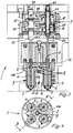
- a multiple-needle closure nozzle for injection molds can contain, according to FIGS. 1 and 2, two and according to FIGS. 3 and 4, four closure needles 4 arranged in a common housing 2 and having a common piston drive, designated as a whole by 3.
- Each valve pin 4 closes a nozzle orifice 5 assigned to it and can be withdrawn in the open position when the injection molding material is filled into the multiple mold.
- a heater 6 is arranged in each case in the area of the nozzle orifices 5.
- feed channels 7 with branches 8 from which the individual sealing needles 4 and the nozzle orifices 5 are each supplied with casting material.
- the common housing 2 viewed in the direction towards the nozzle orifices 5, below the feed channels 7 and their branches or branches 8 in spaced-apart housing parts which have the individual locking needles 4 and their nozzle orifices 5 9 is divided and that these housing parts 9 each have a space 11 between their outer walls 10, but are connected to the common housing 2.
- the housing 2 is given a "udder-like" design, the nozzle orifices 5 being spaced apart from one another by the intermediate space 11 such that they can carry out thermal movements independently of one another and do not damage themselves in the process.
- the distances between the individual housing parts 9 provided below the housing area with the common feed channels 7 and their branching 8 are of such a size that supports 11a fit the entire multiple nozzle 1.
- the spatial separation of the housing parts 9 belonging to the entire housing 2 in the region of the nozzle orifices 5 and the majority of the closure needles 4 thus permits a more stable support of the entire multiple nozzle not only on its outer circumference, but in the areas closer to its center.
- parallel piston rods 12 of the common piston drive act on the individual shut-off needles 4, wherein one can see in FIGS. 1 and 3 in each case several, namely two pistons 14 arranged coaxially to one another and in the direction of displacement, which each act simultaneously on the locking needles 4 of the multiple nozzle 1, that is to say can be accommodated in a very space-saving and compact manner.
- the piston rods 12 thus have at least as many slide guides formed through the passage openings 17 as coaxial drive pistons 14 are connected to them and cylinder chambers 16 for these drive pistons 14 are arranged axially one behind the other. This leads to a very stable holding and guiding of the piston rods 12, so that they do not tilt and the pistons 14 are not tilted even when there is a transverse load through the locking needles 4.
- the piston rods 12 are formed in one piece in the exemplary embodiments.
- a first and a further drive piston 14 are provided, but of course at least a third drive piston could be provided and be displaceable in a separate sealed cylinder chamber arranged axially behind the other cylinder chambers 16 and connected to the piston rods 12, if in a confined space and in view of a low pressure of the drive medium, a higher closing force would be required.
- FIGS. 1 and 3 it can also be seen that the end of the locking needles 4 fits coaxially into an opening or hole 22 in the piston rods 12 via an intermediate body 20 is positively but releasably attached. In this way, forces occurring across the longitudinal extension of the needles 4 can be absorbed well.
- the perforations 22 of the piston rod 12 each extend beyond the piston 14 furthest away from the needle 4 and have an outward opening from which the end of the locking needle 4 or the intermediate body 20 can be reached, so that the valve pin 4 can be pulled out and disassembled through this hole 22 in the piston rod 12.
- the perforation 22 is arranged centrally and concentrically in the piston rod 12 and practically filled by the intermediate body 20, while the cross section of the locking needle 4 is somewhat smaller.
- the perforation 22 has at its end facing away from the locking needle 4 a closure, which in the exemplary embodiment is designed as a screw 24, the inward end face of which simultaneously forms the axial stop for the end of the locking needle 4 or the intermediate body 20 between the closure and the needle end.
- the front, the closure 24 facing end of the intermediate body 20 has a threaded opening 25 for the screw 24, into which a suitable tool can be screwed in order to be able to pull the intermediate body 20 with the locking needle 4 in the axial direction through the piston rod 8.
- a new valve pin 4 can be re-installed in this way, so that replacement of individual valve needles 4 on the multiple nozzle 1 is possible in a simple manner and without mutual interference.
- the multiple valve gate nozzle 1 serves for the simultaneous loading of several individual molds in one injection mold and has two or more locking needles 4 arranged in a common housing 2 and having a common piston drive 3. Each locking needle 4 closes an associated nozzle orifice 5 on the multiple nozzle 1 and can be withdrawn therefrom for the injection of casting material.
- a separate heating device 6 can be arranged in the area of the respective nozzle mouth 5.
- feed channels 7 are provided with branches 8, which lead to the individual locking needles 4 and their mouths 5.
- the common housing 2 is divided below these common feed channels 7 and their branches 8 into spaced apart housing parts 9, which at least partially accommodate the individual locking needles 4 and have their nozzle orifices 5.
- the division is also spatially designed so that these housing parts 9 each have a space 11 between their walls 10 running around the needles 4 and are connected to the common housing 2, if necessary subsequently.
- supports 11 of the multiple nozzle can be accommodated below the common housing area between the housing parts 9.
Abstract
Description
Die Erfindung betrifft eine Mehrfach-Nadelverschluß-Düse für Spritzgießformen mit wenigstens zwei in einem gemeinsamen Gehäuse angeordneten und einen gemeinsamen Kolbenantrieb aufweisenden Verschlußnadeln, deren jede eine ihr zugeordnete Düsenmündung verschließt und im Bereich der Düsenmündung insbesondere eine Heizung aufweist, wobei in dem gemeinsamen Gehäuse Zuführkanäle mit Abzweigungen zu den einzelnen Verschlußnadeln gemeinsam angeordnet sind.The invention relates to a multiple valve gate nozzle for injection molds with at least two locking needles arranged in a common housing and having a common piston drive, each of which closes a nozzle orifice associated with it and in particular has a heater in the region of the nozzle orifice, with supply channels in the common housing Branches to the individual locking needles are arranged together.
Eine solche Mehrfach-Nadelverschluß-Düse ist aus der DE-A-3733363 bekannt.Such a multiple needle valve nozzle is known from DE-A-3733363.
Mehrfach-Nadelverschluß-Düsen sind aus der Praxis bekannt und dienen vorallem dazu, in Mehrfach-Spritzgießformen relativ kleine Teile auf engem Raum spritzen zu können, damit die Mehrfachform bestmöglich ausgenutzt wird. Die einzelnen Mündungen der Mehrfach-Nadelverschlußdüsen können nämlich aufgrund ihres gemeinsamen Antriebes und ihrer Anordnung in einem gemeinsamen Gehäuse so dicht nebeneinander angeordnet werden, daß auch kleine Werkstücke und deren Form-Aussparungen in der Mehrfachform entsprechend dicht bei einander angeordnet werden können.Multiple needle valve nozzles are known from practice and are used primarily to be able to inject relatively small parts in a narrow space in multiple injection molds, so that the multiple mold is used in the best possible way. The individual orifices of the multiple needle valve nozzles can namely because of their common drive and their arrangement in a common housing so closely next to each other that even small workpieces and their shape recesses in the multiple mold can be arranged accordingly close to each other.
Bei den bisher bekannten Mehrfach-Düsen besteht jedoch das Problem, daß vorallem durch die starken Temperaturschwankungen im Mündungsbereich die einzelnen Abdichtringe Maßveränderungen erfahren und sich dabei gegenseitig beschädigen können. Dieses Problem läßt sich nicht dadurch beheben, daß diese Abdichtringe stärker dimensioniert werden, denn dies würde wiederum zu einer stärkeren Reaktion auf Wärmeeinwirkungen führen.With the previously known multiple nozzles, however, there is the problem that the individual sealing rings experience dimensional changes and can damage one another in the process due to the strong temperature fluctuations in the mouth area. This problem cannot be solved by dimensioning these sealing rings more, since this would in turn lead to a stronger reaction to the effects of heat.
Ein weiteres Problem besteht darin, daß diese Mehrfach-Düsen nur unzureichend gegen den Spritzdruck abgestützt werden können, da der Spritzdruck an den einzelnen Düsenmündungen gleichzeitig entsprechend stark wirkt und eine Fixierung nur jeweils am Außenumfang der gesamten Einheit möglich ist. Eine nur an der Außenseite solcher Mehrfach-Düsen erfolgende Abstützung hat sich in der Praxis als unzureichend erwiesen.Another problem is that these multiple nozzles can only be insufficiently supported against the spray pressure, since the spray pressure at the individual nozzle orifices simultaneously has a correspondingly strong effect and can only be fixed on the outer circumference of the entire unit. A support that is only provided on the outside of such multiple nozzles has proven to be insufficient in practice.
Es besteht deshalb die Aufgabe, eine Mehrfach-Nadelverschluß-Düse der eingangs erwähnten Art zu schaffen, bei welcher die Erwärmung im Mündungsbereich nicht zu einer Beschädigung führt und bei welcher gleichzeitig eine gute Abstützung gegen die aus dem Spritzdruck resultierenden Reaktionskräfte möglich ist.It is therefore an object of the invention to provide a multiple valve gate nozzle of the type mentioned, in which the heating in the mouth area does not lead to damage and in which, at the same time, good support is possible against the reaction forces resulting from the injection pressure.
Die Lösung dieser mehrfachen Aufgabe besteht bei einer Mehrfach-Nadelverschluß-Düse mit gemeinsamem Gehäuse darin, daß das gemeinsame Gehäuse unterhalb der Zuführkanäle und/oder deren Verzweigung in voneinander beabstandete, die einzelnen Verschlußnadeln und deren Düsenmündungen aufweisende Gehäuseteile aufgeteilt ist, daß diese Gehäuseteile jeweils zwischen ihren Wandungen einen Zwischenraum haben und mit dem gemeinsamen Gehäuse verbunden sind, und daß die unterhalb des Gehäusebereiches mit den gemeinsamen Zuführkanälen und deren Verzweigung vorgesehenen Abstände oder Zwischenräume der einzelnen Gehäuseteile eine derartige Größe haben, daß dazwischen eine Abstützung der Mehrfach-Düse - gegenüber der Spritzgießform - paßt.The solution to this multiple task in a multiple needle valve nozzle with a common housing is that the common housing below the feed channels and / or their branching is divided into spaced housing parts which have the individual locking needles and their nozzle orifices, that these housing parts are each between their walls have a space and are connected to the common housing, and that the distances or spaces between the individual housing parts provided below the housing area with the common feed channels and their branching are of such a size that a support for the multiple nozzle - in relation to the injection mold - fits between them.
Die an dem gemeinsamen Gehäuse jeweils voneinander getrennten Gehäuseteile können somit aufgrund ihres Abstandes im Mündungsbereich beliebige Wärmebewegungen durchführen, ohne sich gegenseitig zu beeinflussen und zu beschädigen.The housing parts, which are separated from one another on the common housing, can therefore be located in the mouth region on account of their distance Carry out any heat movements without influencing and damaging each other.
Darüberhinaus kann durch eine Abstützung der Mehrfach-Düse der Spritzdruck wesentlich besser und gegenüber den Einzel-Düsenmündungen und Verschlußnadeln gleichmäßiger aufgefangen werden, wodurch auch eine unnötig stark dimensionierte Bauweise vermieden werden kann.In addition, by supporting the multiple nozzle, the spray pressure can be absorbed much better and more uniformly than the individual nozzle orifices and locking needles, which also makes it possible to avoid an unnecessarily large construction.
Die Erfindung erlaubt eine vorteilhafte Ausgestaltung bezüglich der Heizvorrichtung an der Düsenmündung, welche darin bestehen kann, daß an den einzelnen Düsenmündungen der voneinander beabstandeten Gehäuseteile jeweils eine eigene Heizvorrichtung angeordnet ist und jede Heizvorrichtung oder Düsenmündung einen eigenen Temperaturwächter oder Sensor für eine unabhängige Temperaturregelung jeder Einzeldüse der Mehrfach-Nadelverschluß-Düse aufweist. Während bei den bisherigen Mehrfachdüsen eine gemeinsame Heizung für alle Mündungen vorzusehen war, können also durch die erfindungsgemäße Anordnung die einzelnen Düsenmündungen präzise auf eine erforderliche Temperatur eingeregelt werden. Gleichzeitig werden ungewollte Temperaturbeeinflussungen der einzelnen Düsenmündungen gegeneinander ausgeschlossen.The invention allows an advantageous embodiment with respect to the heating device at the nozzle mouth, which may consist in that a separate heating device is arranged on the individual nozzle mouths of the spaced apart housing parts and each heating device or nozzle mouth has its own temperature monitor or sensor for independent temperature control of each individual nozzle Has multiple needle valve nozzle. While in the previous multiple nozzles a common heating was to be provided for all the orifices, the arrangement of the invention allows the individual nozzle orifices to be precisely regulated to a required temperature. At the same time unwanted temperature influences of the individual nozzle orifices against each other are excluded.
Für einen präzisen, synchronen und vorallem platzsparenden Antrieb der Verschlußnadeln ist es zweckmäßig, wenn an den einzelnen Verschlußnadeln - der jeweiligen Mehrfach-Nadelverschluß-Düse - jeweils parallele Kolbenstangen des gemeinsamen Kolbenantriebes angreifen und jeweils mehrere koaxial zueinander und in Verschieberichtung hintereinander angeordnete Kolben gleichzeitig auf die Verschlußnadeln wirkend vorgesehen sind. Es ist also für eine Mehrfach-Nadelverschluß-Düse ein Kolben vorgesehen, der mehrere Kolbenstangen gleichzeitig, nämlich für jede Nadelverschlußdüse eine, beaufschlagt und in axialer Richtung hinter diesem Kolben ist wenigstens ein weiterer Kolben vorhanden, um eine genügend große Schließkraft auf die Verschlußnadeln zu übertragen.For a precise, synchronous and, above all, space-saving drive of the shut-off needles, it is expedient if the individual shut-off needles - the respective multiple-needle shut-off nozzle - engage parallel piston rods of the common piston drive and each have several pistons arranged coaxially to one another and in the direction of displacement are simultaneously provided acting on the locking needles. A piston is therefore provided for a multiple needle valve, which acts on several piston rods simultaneously, namely one for each valve valve, and at least one additional piston is present in the axial direction behind this piston in order to transmit a sufficiently large closing force to the valve needles .
Dabei ist es besonders zweckmäßig, wenn die gemeinsam auf die Verschlußnadeln wirkenden Antriebskolben an gemeinsamen, durchgehenden Kolbenstangen befestigt sind und wenn die Kolbenstangen jeweils einen Boden der die einzelnen Kolben enthaltenden, in Vorschubrichtung koaxial hintereinander angeordneten Zylinderkammern durchsetzen und in den Durchtrittsöffnungen der Böden gleitend geführt sind.It is particularly expedient if the drive pistons acting jointly on the locking needles are fastened to common, continuous piston rods and if the piston rods each penetrate a bottom of the cylinder chambers containing the individual pistons, which are arranged coaxially one behind the other in the feed direction, and are slidably guided in the passage openings of the bottoms .
Dadurch ergibt sich für die einzelnen Kolbenstangen der Mehrfachdüse aufgrund der Verwendung mehrerer Kolben und entsprechend mehrerer Zylinder mit Böden die Möglichkeit, wenigstens zwei oder mehr Gleitführungen hintereinander anzuordnen. Da außerdem mehrere derartige durchgehende Kolbenstangen parallel zueinander vorgesehen sind und jede in der erwähnten Weise mehrfach geführt ist, ergibt sich eine derart präzise Führung, daß ein Verkippen der Kolbenstangen und demgemäß ein Verkanten der Kolben selbst praktisch ausgeschlossen wird. Somit wird auch die Gefahr vermieden, daß ein beispielsweise relativ geringer Druck des Druckmediums von zum Beispiel 3, 4, 5 oder 6 Bar nicht ausreichen könnte, um an der Mehrfachdüse bei allen Verschlußnadeln die erforderliche Schließkraft aufzubringen.This results in the possibility of arranging at least two or more sliding guides one behind the other for the individual piston rods of the multiple nozzle due to the use of several pistons and correspondingly several cylinders with bottoms. In addition, since several such continuous piston rods are provided parallel to one another and each is guided several times in the manner mentioned, such a precise guidance results that tilting of the piston rods and accordingly tilting of the pistons themselves is practically excluded. This also avoids the risk that, for example, a relatively low pressure of the pressure medium of, for example, 3, 4, 5 or 6 bar might not be sufficient to apply the required closing force to the multi-nozzle for all locking needles.
Dabei können die Kolbenstangen wenigstens soviele Gleitführungen haben, wie koaxiale Antriebskolben mit ihnen verbunden und Zylinderkammern für diese Antriebskolben axial hintereinander angeordnet sind. Besonders zweckmäßig ist es dabei, wenn die Kolbenstangen jeweils einstückig ausgebildet sind. Dabei können die Kolbenstangen den von den Verschlußnadeln am weitesten abliegenden Kolben mit einem Überstand überragen und der Überstand kann in dem Zylinderdeckel oder -abschluß - dieses entferntesten Kolbens - geführt sein, wodurch sich noch eine zusätzliche Führungsmöglichkeit ergibt.The piston rods can have at least as many sliding guides as coaxial drive pistons are connected to them and cylinder chambers for these drive pistons are arranged axially one behind the other. It is particularly expedient if the piston rods are each formed in one piece. You can the piston rods protrude beyond the piston furthest away from the locking needles with a protrusion and the protrusion can be guided in the cylinder cover or end - this most distant piston -, which results in an additional guide option.
Zur Verbesserung der Schließkraft ist es aufgrund der gemeinsamen Kolbenstangen und deren guten Führungen möglich, daß zusätzlich zu dem ersten und dem weiteren Antriebskolben wenigstens ein dritter Antriebskolben vorgesehen ist und in einer axial hinter den übrigen Zylinderkammern angeordneten eigenen abgeschlossenen und abgedichteten Zylinderkammer verschiebbar und mit der Kolbenstange verbunden angeordnet ist. Dies erlaubt es, den Durchmesser des Kolbenantriebes relativ klein zu halten, so daß er auf den Platzbedarf beschränkt bleiben kann, den das gemeinsame Gehäuse der Mehrfachdüse benötigt. Dennoch kann auch bei beschränktem Platz die erforderliche, häufig erhebliche Verschlußkraft auf diese Weise mit ausreichender Sicherheit aufgebracht werden, selbst wenn nur ein relativ geringer Preßluftdruck von zum Beispiel etwa 4 bis 6 Bar zur Verfügung steht.To improve the closing force, it is possible due to the common piston rods and their good guides that, in addition to the first and the further drive pistons, at least a third drive piston is provided and can be displaced in a separate, sealed cylinder chamber arranged axially behind the other cylinder chambers and with the piston rod is connected connected. This allows the diameter of the piston drive to be kept relatively small, so that it can remain limited to the space required by the common housing of the multiple nozzle. Nevertheless, the required, often considerable sealing force can be applied with sufficient security even with limited space, even if only a relatively low compressed air pressure of, for example, about 4 to 6 bar is available.
Eine besonders zweckmäßige Ausgestaltung der Erfindung, die gleichzeitig eine gute Fixierung der einzelnen Verschlußnadeln innerhalb der Mehrfachdüse erlaubt und dabei die präzise Führung der Kolbenstangen ausnutzen kann, kann darin bestehen, daß das Ende der Verschlußnadeln koaxial in eine Aussparung oder Lochung der Kolbenstangen paßt und darin formschlüssig aber lösbar befestigt ist. Die Verschlußnadeln können somit von den Kolbenstangen nicht nur in axialer, sondern auch in Querrichtung gehalten werden.A particularly expedient embodiment of the invention, which at the same time allows a good fixation of the individual locking needles within the multiple nozzle and can thereby take advantage of the precise guidance of the piston rods, can consist in the fact that the end of the locking needles fits coaxially into a recess or perforation in the piston rods and is form-fitting therein but is releasably attached. The locking pins can thus be held not only in the axial but also in the transverse direction by the piston rods.
Dabei ist es möglich, daß die Lochung der Kolbenstange bis über den von der Nadel am weitesten entfernten Kolben hinausführt und eine nach außen gerichtete Mündung hat, von welcher aus das Ende der Verschlußnadel erreichbar ist, und wenn die Verschlußnadel durch die Lochung der Kolbenstange herausziehbar und demontierbar ist, wobei die Lochung insbesondere zentral und konzentrisch in der Kolbenstange angeordnet sein kann. Dies erleichtert es, eine beschädigte oder verschlissene Verschlußnadel auf einfache Weise und ohne Demontage der gesamten Mehrfach-Düse auswechseln zu können, wobei jede einzelne Verschlußnadel der Mehrfachdüse auf diese Weise unabhängig von den anderen ausgewechselt werden kann.It is possible that the perforation of the piston rod extends beyond the piston furthest away from the needle and has an outwardly directed mouth, from which can be reached from the end of the locking needle, and if the locking needle can be pulled out and disassembled through the perforation of the piston rod, wherein the perforation can in particular be arranged centrally and concentrically in the piston rod. This makes it easier to be able to replace a damaged or worn shut-off needle in a simple manner and without dismantling the entire multiple nozzle, each individual shut-off needle of the multiple nozzle being able to be replaced in this way independently of the others.
Die durch die Kolbenstange durchgehende Lochung zur Aufnahme und zum Demontieren der Verschlußnadel kann einen an ihrem der Verschlußnadel abgewandten Ende anbringbaren Verschluß vorzugsweise einen Schraubverschluß, insbesondere eine als Verschluß dienende Schraube, aufweisen, deren nach innen gerichtete Stirnseite gleichzeitig den axialen Anschlag für das Ende der Verschlußnadel oder einen Zwischenkörper zwischen Verschluß und Nadelende bilden kann.The through hole through the piston rod for receiving and disassembling the valve pin can preferably have a screw cap on its end facing away from the valve pin, in particular a screw serving as a screw, the inward end face of which simultaneously provides the axial stop for the end of the valve pin or can form an intermediate body between the closure and the needle end.
Nach Entfernen der Schraube wird die Nadel oder der mit ihr gekuppelte Zwischenkörper zuganglich und kann in axialer Richtung mit der Nadel herausgezogen werden.After removing the screw, the needle or the intermediate body coupled to it becomes accessible and can be pulled out in the axial direction with the needle.
Dabei kann das stirnseitige Ende der Verschlußnadel oder des Zwischenkörpers eine Lochung mit Hinterschneidung oder Gewinde haben, in welche von außen her durch die Lochung der Kolbenstange ein dazu passendes Werkzeug oder eine Zugschraube einsetzbar ist, womit die Verschlußnadel insbesondere mit dem Zwischenkörper in axialer Richtung durch die Kolbenstange herausziehbar ist.The front end of the locking needle or the intermediate body can have a perforation with an undercut or thread, into which a suitable tool or a tension screw can be inserted from the outside through the perforation of the piston rod, whereby the locking needle in particular with the intermediate body in the axial direction through the Piston rod can be pulled out.
Durch die Erfindung ergibt sich also die Möglichkeit, eine Mehrfach-Nadelverschluß-Düse vorzusehen, bei welcher auf engem Raum mehrere Verschlußnadeln mit ausreichender Kraft angetrieben werden können, selbst wenn nur ein relativ geringer Druck des Druckmediums zur Verfügung steht, wobei trotzdem in dem empfindlichen Mündungsbereich eine gegenseitige Beschädigung bei Wärmedehnungen ausgeschaltet und erforderlichenfalls eine zusätzliche Abstützung ermöglicht wird. Im Mündungsbereich ergeben sich also praktisch die Vorteile, die auch einzelne Nadelverschluß-Düsen jeweils nur mit einer Verschlußnadel haben, das heißt jede Düsenmündung ist unabhängig von der anderen und kann auch bezüglich ihrer Temperatur unabhängig von der Nachbar-Düsenmündung geregelt werden, obwohl alle Mündungen zu einer gemeinsamen Mehrfach-Nadelverschluß-Düse gehören.The invention thus makes it possible to provide a multiple needle shut-off nozzle in which a plurality of shut-off needles can be driven with sufficient force in a narrow space, even if only a relatively low pressure of the pressure medium is available, although mutual damage in the case of thermal expansions is eliminated in the sensitive mouth region and, if necessary, additional support is made possible. In the mouth area, there are practically the advantages that individual needle valve nozzles only have one valve needle, i.e. each nozzle mouth is independent of the other and its temperature can be regulated independently of the neighboring nozzle mouth, although all the mouths are closed belong to a common multiple valve gate nozzle.
Nachstehend sind Ausführungsbeispiele der Erfindung anhand der Zeichnung näher beschrieben. Es zeigt in zum Teil schematisierter Darstellung:
- Fig. 1
- einen Teillängsschnitt durch eine Mehrfach-Nadelverschluß-Düse mit zwei Verschlußnadeln und zwei Düsenmündungen gemäß der Schnittlinie A-A in
Figur 2, - Fig. 2
- eine Draufsicht einer Zweifach-Nadelverschluß-Düse ohne den Kolbenantrieb,
- Fig. 3
- einen der
Figur 1 entsprechenden Schnitt durch eine Vierfach-Nadelverschluß-Düse gemäß der Schnittlinie B-B inFigur 4, und - Fig. 4
- eine Draufsicht der Vierfach-Nadelverschluß-Düse gemäß
Figur 3 ohne den Kolbenantrieb.
- Fig. 1
- 3 shows a partial longitudinal section through a multiple valve gate nozzle with two valve needles and two nozzle orifices according to section line AA in FIG. 2,
- Fig. 2
- a plan view of a double needle valve nozzle without the piston drive,
- Fig. 3
- a section corresponding to Figure 1 through a four-way valve gate nozzle according to section line BB in Figure 4, and
- Fig. 4
- a plan view of the four-way valve gate nozzle according to Figure 3 without the piston drive.
Bei der nachfolgenden Beschreibung zweier Ausführungsbeispiele erhalten übereinstimmende Teile oder Teile mit übereinstimmenden Funktionen auch bei jeweils abgewandelter Gestaltung übereinstimmende Bezugszahlen.In the following description of two exemplary embodiments, matching parts or parts with matching functions receive matching reference numbers even with a modified design.
Eine im Ganzen mit 1 bezeichnete Mehrfach-Nadelverschluß-Düse für Spritzgießformen kann gemäß Figur 1 und 2 zwei und gemäß Figur 3 und 4 vier in einem gemeinsamen Gehäuse 2 angeordnete und einen gemeinsamen, im Ganzen mit 3 bezeichneten Kolbenantrieb aufweisende Verschlußnadeln 4 enthalten.A multiple-needle closure nozzle for injection molds, designated as a whole by 1, can contain, according to FIGS. 1 and 2, two and according to FIGS. 3 and 4, four
Jede Verschlußnadel 4 verschließt eine ihr zugeordnete Düsenmündung 5 und kann in Offenstellung zurückgezogen werden, wenn der Spritzgießwerkstoff in die Mehrfachform eingefüllt wird. Dabei ist im Bereich der Düsenmündungen 5 jeweils eine Heizung 6 angeordnet.Each
In dem gemeinsamen Gehäuse 2 erkennt man Zuführkanäle 7 mit Abzweigungen 8, von welchen aus die einzelnen Verschlußnadeln 4 und die Düsenmündungen 5 jeweils mit Gießwerkstoff versorgt werden.In the
Sowohl in Figur 1 als auch in Figur 3 erkennt man deutlich, daß das gemeinsame Gehäuse 2 in Richtung zu den Düsenmündungen 5 hin gesehen unterhalb der Zuführkanäle 7 und deren Verzweigungen oder Abzweigungen 8 in voneinander beabstandete, die einzelnen Verschlußnadeln 4 und deren Düsenmündungen 5 aufweisende Gehäuseteile 9 aufgeteilt ist und daß diese Gehäuseteile 9 jeweils zwischen ihren äußeren Wandungen 10 einen Zwischenraum 11 haben, jedoch mit dem gemeinsamen Gehäuse 2 verbunden sind. Das Gehäuse 2 erhält auf diese Weise eine "euterähnliche" Gestaltung, wobei die Düsenmündungen 5 durch den Zwischenraum 11 so voneinander beabstandet sind, daß sie unabhängig voneinander Wärmebewegungen durchführen können und sich dabei nicht schädigen.Both in FIG. 1 and in FIG. 3, it can be clearly seen that the
In allen Figuren ist angedeutet, daß die unterhalb des Gehäusebereiches mit den gemeinsamen Zuführkanälen 7 und deren Verzweigung 8 vorgesehenen Abstände der einzelnen Gehäuseteile 9 eine derartige Größe haben, daß dazwischen Abstützungen 11a der gesamten Mehrfach-Düse 1 passen. Die räumliche Trennung der zu dem gesamten Gehäuse 2 gehörenden Gehäuseteile 9 im Bereich der Düsenmündungen 5 und des größten Teiles der Verschlußnadeln 4 erlaubt also eine stabilere Abstützung der gesamten Mehrfachdüse nicht nur an ihrem Außenumfang, sondern in ihrem Zentrum näherliegenden Bereichen.In all figures it is indicated that the distances between the
Die Heizungen 6 an den Düsenmündungen 5 wurden bereits erwähnt. In Figur 1 und 3 erkennt man deutlich, daß an den einzelnen Düsenmündungen 5 der voneinander beabstandeten Gehäuseteile 9 jeweils eine eigene Heizvorrichtung 6 angeordnet ist, so daß jede Heizvorrichtung 6 oder Düsenmündung 5 einen eigenen Temperaturwächter oder Sensor für eine unabhängige Temperaturregelung jeder Einzeldüse dieser Mehrfach-Nadelverschluß-Düse 1 haben kann. Entsprechend gute Spritzgießergebnisse lassen sich mit einer solchen Mehrfach-Düse 1 erreichen.The
Für den Antrieb der Verschlußnadeln greifen an den einzelnen Verschlußnadeln 4 jeweils parallele Kolbenstangen 12 des gemeinsamen, im Ganzen mit 3 bezeichneten Kolbenantriebes an, wobei man in Figur 1 und 3 jeweils mehrere, nämlich zwei koaxial zueinander und in Verschieberichtung hintereinander angeordnete Kolben 14 erkennt, die jeweils gleichzeitig auf die Verschlußnadeln 4 der Mehrfachdüse 1 wirken, also sehr platzsparend und kompakt untergebracht werden können.For driving the shut-off needles,
Damit dabei keine gegenseitige Beeinflussung der Verschlußnadeln über den Kolbenantrieb 3 erfolgen kann, wenn die Verschlußnadeln 4 beispielsweise durch einströmenden Gießwerkstoff auch in Querrichtung belastet werden, ist in beiden Ausführungsbeispielen vorgesehen, daß die gemeinsam auf die Verschlußnadeln 4 wirkenden Antriebskolben 14 an gemeinsamen, durchgehenden Kolbenstangen 12 befestigt sind und daß die Kolbenstangen 12 jeweils einen Boden 15 der die einzelnen Kolben 14 enthaltenden, in Vorschubrichtung koaxial hintereinander angeordneten Zylinderkammern 16 durchsetzen und in den Durchtrittsöffnungen 17 der Böden 15 gleitend geführt sind.So that there is no mutual interference between the locking needles via the
Die Kolbenstangen 12 haben also wenigstens soviele durch die Durchtrittsöffnungen 17 gebildete Gleitführungen, wie koaxiale Antriebskolben 14 mit ihnen jeweils verbunden und Zylinderkammern 16 für diese Antriebskolben 14 axial hintereinander angeordnet sind. Dies führt zu einer sehr stabilen Halterung und Führung der Kolbenstangen 12, so daß sie auch bei einer Querbelastung durch die Verschlußnadeln 4 nicht verkippt und die Kolben 14 nicht verkantet werden. Dabei sind die Kolbenstangen 12 in den Ausführungsbeispielen einstückig ausgebildet.The
In Figur 1 und 3 erkennt man, daß die Führung und Festlegung der Kolbenstangen 12 gegen seitliche Auslenkungen oder Verkippungen noch dadurch verbessert sind, daß die Kolbenstangen 12 den von den Verschlußnadeln 4 am weitesten abliegenden Kolben 14 mit einem Überstand 18 überragen und der Überstand 18 in dem Zylinderdeckel oder -abschluß 19 geführt ist. Somit ergeben sich in diesem Falle sogar bei zwei Antriebskolben 14 drei Gleitführungen für die jeweilige Kolbenstange 12.In Figures 1 and 3 it can be seen that the guidance and fixing of the
In beiden Ausführungsbeispielen ist ein erster und ein weiterer Antriebskolben 14 vorgesehen, jedoch könnte selbstverständlich wenigstens ein dritter Antriebskolben vorgesehen sein und in einer axial hinter den übrigen Zylinderkammern 16 angeordneten eigenen weiteren abgedichteten Zylinderkammer verschiebbar und mit den Kolbenstangen 12 verbunden angeordnet sein, falls auf engem Raum und im Hinblick auf einen geringen Druck des Antriebsmediums eine höhere Schließkraft erforderlich wäre.In both exemplary embodiments, a first and a
In Figur 1 und 3 ist noch erkennbar, daß das Ende der Verschlußnadeln 4 jeweils über einen Zwischenkörper 20 koaxial in eine Aussparung oder Lochung 22 der Kolbenstangen 12 paßt und formschlüssig aber lösbar befestigt ist. Dadurch können quer zur Längserstreckung der Nadeln 4 auftretende Kräfte gut aufgefangen werden.In FIGS. 1 and 3 it can also be seen that the end of the locking needles 4 fits coaxially into an opening or
Ferner erkennt man, daß die Lochung 22 der Kolbenstange 12 jeweils bis über den von der Nadel 4 am weitesten entfernten Kolben 14 hinausführt und eine nach außen gerichtete Mündung hat, von welcher aus das Ende der Verschlußnadel 4 bzw. der Zwischenkörper 20 erreichbar ist, so daß die Verschlußnadel 4 durch diese Lochung 22 der Kolbenstange 12 herausziehbar und demontierbar ist. Die Lochung 22 ist dabei zentral und konzentrisch in der Kolbenstange 12 angeordnet und von dem Zwischenkörper 20 praktisch ausgefüllt, während der Querschnitt der Verschlußnadel 4 etwas geringer ist.It can also be seen that the
Die Lochung 22 hat an ihrem der Verschlußnadel 4 abgewandten Ende einen Verschluß, der im Ausführungsbeispiel als Schraube 24 ausgebildet ist, deren nach innen gerichtete Stirnseite gleichzeitig den axialen Anschlag für das Ende der Verschlußnadel 4 oder den Zwischenkörper 20 zwischen Verschluß und Nadelende bildet.The
Das stirnseitige, dem Verschluß 24 zugewandte Ende des Zwischenkörpers 20 hat eine Gewindeöffnung 25 für die Schraube 24, in welche ein dazu passendes Werkzeug eingeschraubt werden kann, um den Zwischenkörper 20 mit der Verschlußnadel 4 in axialer Richtung durch die Kolbenstange 8 herausziehen zu können. Umgekehrt kann auf diese Weise eine neue Verschlußnadel 4 wieder montiert werden, so daß ein Auswechseln einzelner Verschlußnadeln 4 an der Mehrfachdüse 1 auf einfache Weise und ohne gegenseitige Beeinflussung möglich ist.The front, the
Die Mehrfach-Nadelverschluß-Düse 1 gemäß den verschiedenen Ausführungsbeispielen dient zur gleichzeitigen Beaufschlagung mehrerer Einzelformen in einer Spritzgießform und hat zwei oder mehr in einem gemeinsamen Gehäuse 2 angeordnete und einen gemeinsamen Kolbenantrieb 3 aufweisende Verschlußnadeln 4. Jede Verschlußnadel 4 verschließt an der Mehrfach-Düse 1 eine ihr zugeordnete Düsenmündung 5 und kann von dieser für das Einspritzen von Gießwerkstoff zurückgezogen werden. Dabei kann im Bereich der jeweiligen Düsenmündung 5 eine eigene Heizvorrichtung 6 angeordnet sein. In dem gemeinsamen Gehäuse 2 sind Zuführkanäle 7 mit Verzweigungen 8 vorgesehen, die zu den einzelnen Verschlußnadeln 4 und deren Mündungen 5 führen. Das gemeinsame Gehäuse 2 ist dabei unterhalb diesen gemeinsamen Zuführkanälen 7 und deren Verzweigungen 8 in voneinander beabstandete, die einzelnen Verschlußnadeln 4 zumindest zum Teil aufnehmende und deren Düsenmündungen 5 aufweisende Gehäuseteile 9 aufgeteilt. Die Aufteilung ist dabei auch räumlich so gestaltet, daß diese Gehäuseteile 9 jeweils zwischen ihren rund um die Nadeln 4 verlaufenden Wandungen 10 einen Zwischenraum 11 haben und mit dem gemeinsamen Gehäuse 2 - gegebenenfalls nachträglich - verbunden sind. Somit können unterhalb des gemeinsamen Gehäusebereiches zwischen den Gehäuseteilen 9 Abstützungen 11 der Mehrfach-Düse untergebracht werden.The multiple
Claims (12)
- A multiple needle valve nozzle (1) for injection moulds, including at least two valve needles (4) arranged in a common housing (2) and having a common piston drive (3), each valve needle closing a nozzle opening (5) associated thereto and having in particular a heating means (6) in the region of the nozzle opening 5), wherein feed channels (7) with branches (8) to the individual valve needles (4) are jointly arranged in the common housing (2), characterized in that below the feed channels (7) and/or their branches (8) the common housing (2) is divided into mutually spaced housing parts (9) having the individual valve needles (4) and their nozzle openings (5), that said housing parts (9) in each case have an interspace (11) between their walls (10) and are connected to the common housing (2), and that the spacing of the individual housing parts (9), as is provided below the housing zone with the common feed channels (7) and their branches (8), is of such a size that a support (11a) for the multiple nozzle (1) fits therebetween.
- A multiple needle valve nozzle as claimed in claim 1, characterized in that a separate heating means (6) is arranged at each of the individual nozzle openings (5) of the mutually spaced housing parts (9) and each heating means (6) or nozzle opening (5) has its own temperature monitor or sensor for independent temperature control of each individual nozzle of the multiple needle valve nozzle (1).
- A multiple needle valve nozzle as claimed in claim 1 or claim 2, characterized in that the individual valve needles (4) are engaged by parallel piston rods (12) of the common piston drive (3) and a plurality of pistons (14) are provided which are arranged coaxially one behind the other in a displacement direction and act simultaneously on the valve needles (4).
- A multiple needle valve nozzle as claimed in any one of claims 1 to 3, characterized in that the drive pistons (14) acting in common on the valve needles (4) are fixed to common, throughgoing piston rods (12), and that the piston rods (12) in each case pass through a floor (15) of the cylinder chambers (16) which contain the individual pistons (14) and are arranged coaxially one behind the other in the forward feed direction, said piston rods (12) in each case being slidably guided in the passage openings (17) in the floors (15).
- A multiple needle valve nozzle as claimed in any one of claims 1 to 4, characterized in that the piston rods (12) have sliding guides of a number at least as great as that of coaxial pistons (14) connected thereto and that of cylinder chambers (16) arranged axially one behind the other for said drive pistons (14).
- A multiple needle valve nozzle as claimed in any one of claims 1 to 5, characterized in that the piston rods (12) are of integral design.
- A multiple needle valve nozzle as claimed in any one of claims 1 to 6, characterized in that the piston rods (12) have a projecting portion (18) which projects past the piston (14) most remote from the valve needles (4) and is guided in the cylinder lid or closure (19).
- A multiple needle valve nozzle as claimed in any one of claims 1 to 7, characterized in that in addition to the drive pistons (14), provision is made for at least one further drive piston (14), for example a third one, which is displaceably arranged in a separate, sealed off cylinder chamber arranged axially behind the other cylinder chambers (16) and is connected to the piston rods (12).
- A multiple needle valve nozzle as claimed in any one of claims 1 to 8, characterized in that the ends of the valve needles (4) fit coaxially into a bore (22) of the piston rods (12), particularly via intermediate bodies (20), and are fixed positively but releasably.
- A multiple needle valve nozzle as claimed in any one of claims 1 to 9, characterized in that the bore (22) of the piston rod (12) extends beyond the piston (14) furthest removed from the needles (4) and has an outwardly directed opening affording access to the end of the valve needle (4) and that the valve needle is adapted to be pulled out and disassembled via the bore (22) in the piston rod (12), in particular the bore (22) being arranged centrally and concentrically in the piston rod (12).
- A multiple needle valve nozzle as claimed in any one of claims 1 to 10, characterized in that the bore (22) passing through the piston rod (12) for receiving and disassembling the valve needle (4) and particularly its intermediate body (20) has a closure, preferably a screw plug, particularly a screw (24) serving as closure, adapted to be applied to the bore-end remote from the valve needle (4), the inwardly directed end face of which can simultaneously constitute the axial stop for the end of the valve needle (4) or for the body (20) intermediate closure and needle end.
- A multiple needle valve nozzle as claimed in any one of claims 1 to 11, characterized in that the front end of the valve needle (4) or of the intermediate body (20) has a bore with an undercut or thread into which a matching tool or pulling bolt can be set from the outside through the bore (20) in the piston rod (12), whereby the valve needle (4), particularly with the intermediate body (20), can be pulled out in the axial direction through the piston rod (12).
Applications Claiming Priority (3)
| Application Number | Priority Date | Filing Date | Title |
|---|---|---|---|
| DE4206318A DE4206318C2 (en) | 1992-02-29 | 1992-02-29 | Multiple needle valve nozzle for injection molds |
| DE4206318 | 1992-02-29 | ||
| US08/113,400 US5368470A (en) | 1992-02-29 | 1993-08-27 | Multiple pin closure nozzle assembly for injection molds |
Publications (2)
| Publication Number | Publication Date |
|---|---|
| EP0558932A1 EP0558932A1 (en) | 1993-09-08 |
| EP0558932B1 true EP0558932B1 (en) | 1996-01-10 |
Family
ID=25912336
Family Applications (1)
| Application Number | Title | Priority Date | Filing Date |
|---|---|---|---|
| EP93101486A Expired - Lifetime EP0558932B1 (en) | 1992-02-29 | 1993-01-30 | Multiple needle valve nozzle for injection moulds |
Country Status (6)
| Country | Link |
|---|---|
| US (1) | US5368470A (en) |
| EP (1) | EP0558932B1 (en) |
| JP (1) | JP3113087B2 (en) |
| AT (1) | ATE132798T1 (en) |
| DE (2) | DE4206318C2 (en) |
| DK (1) | DK0558932T3 (en) |
Cited By (2)
| Publication number | Priority date | Publication date | Assignee | Title |
|---|---|---|---|---|
| USRE41648E1 (en) | 2002-03-14 | 2010-09-07 | Mold-Masters (2007) Limited | Valve-gated injection molding system with side-mounted actuator |
| KR101880476B1 (en) | 2014-03-10 | 2018-07-23 | 인글라스 에스피에이 | Fixing plate of the mold of an injection molding apparatus of plastic material |
Families Citing this family (19)
| Publication number | Priority date | Publication date | Assignee | Title |
|---|---|---|---|---|
| US5650178A (en) * | 1994-11-23 | 1997-07-22 | Bemis Manufacturing Company | Co-injection manifold for injection molding |
| CA2264224A1 (en) * | 1999-02-26 | 2000-08-26 | Denis Babin | Multi-cavity injection molding apparatus splitting melt near nozzle front |
| WO2000051803A1 (en) * | 1999-02-26 | 2000-09-08 | Mold-Masters Limited | Multi-cavity injection molding apparatus splitting melt near nozzle front |
| US6974556B2 (en) * | 2000-02-29 | 2005-12-13 | Bemis Manufacturing Company | Co-injection apparatus for injection molding |
| US6386508B1 (en) | 2000-06-05 | 2002-05-14 | D-M-E Company | Actuator having dual piston surfaces |
| US6755641B1 (en) * | 2000-09-01 | 2004-06-29 | Mold-Masters Limited | Stack injection molding apparatus with separately actuated arrays of valve gates |
| CA2364050A1 (en) * | 2000-11-30 | 2002-05-30 | Bemis Manufacturing Company | Co-injection methods using endothermic-blowing agents and products made therefrom |
| DE10231093C1 (en) * | 2002-07-10 | 2003-10-30 | Otto Maenner Heiskanalsysteme | Injection jet, for plastics injection molding, has at least two opposing outflow openings at different sides, each with a closure needle to prevent the formation of a cold plug at the opening mouth |
| CA2437076C (en) * | 2002-08-14 | 2010-10-12 | Mold-Masters Limited | Valve pin adjustment device |
| US6719263B1 (en) | 2002-09-20 | 2004-04-13 | D-M-E Company | Multi-piston valve actuator |
| EP1418034B1 (en) * | 2002-11-05 | 2007-02-21 | Mold-Masters Limited | Tight pitch nozzle with individual valve gate control |
| DE202004019328U1 (en) * | 2004-10-20 | 2005-02-24 | Mold-Masters Ltd., Georgetown | Needle valve nozzle for injection molding plastics has a mechanism to prevent needle rotation during needle adjustment |
| DE102005049605A1 (en) * | 2004-10-19 | 2006-04-20 | Mold-Masters Ltd., Georgetown | Manifold plug for hot runner injection system lies between back plate and tool plate, fits in manifold bore, has channel linking manifold and nozzle melt channels and integral pressure disc pressed against back plate |
| KR100810667B1 (en) * | 2004-12-15 | 2008-03-07 | 허남욱 | Multo hot runner valve system |
| US7390184B2 (en) * | 2005-11-09 | 2008-06-24 | Centoco Plastics Limited | Dual injection manifold |
| EP2008790A2 (en) | 2007-06-27 | 2008-12-31 | AWM Mold Tech AG | Needle lock nozzle assembly |
| US7618253B2 (en) * | 2007-10-19 | 2009-11-17 | Mold-Masters (2007) Limited | Multiple-gate injection molding apparatus |
| CN108908860A (en) * | 2018-06-30 | 2018-11-30 | 深圳市麦士德福科技股份有限公司 | A kind of mold for injection molding thermoset plastics |
| CN110720482B (en) * | 2019-10-25 | 2021-07-27 | 马鞍山市春晖食品有限责任公司 | Food slip casting machine |
Family Cites Families (13)
| Publication number | Priority date | Publication date | Assignee | Title |
|---|---|---|---|---|
| DE2004212A1 (en) * | 1970-01-30 | 1971-08-05 | Louis Felder | Pressurized piston-cylinder arrangement |
| US3847528A (en) * | 1972-11-29 | 1974-11-12 | Improved Machinery Inc | Clamping force applying means for molding machines |
| US4279582A (en) * | 1979-04-02 | 1981-07-21 | Incoe Corporation | Method and apparatus for individual control of injection mold shut-off bushings |
| EP0021273B1 (en) * | 1979-06-12 | 1984-09-12 | Hendrikus Jacobus Elisabeth Schouenberg | Injection mechanism for molding plastics |
| DE3249486C2 (en) * | 1982-12-09 | 1992-03-05 | Männer, Otto, 7836 Bahlingen | Valve gate nozzle with piston drive for injection molds |
| DE3336258C2 (en) * | 1983-10-05 | 1986-04-17 | HASCO-Normalien Hasenclever & Co, 5880 Lüdenscheid | Injection molding or pressing tool for processing plastic masses |
| DE3403603C2 (en) * | 1984-02-02 | 1985-12-05 | Maschinenfabrik Köppern GmbH & Co KG, 4320 Hattingen | Force-controlled valve gate for injection nozzles in injection molds |
| DE3590090C2 (en) * | 1984-02-28 | 1989-12-14 | Ju-Oh Trading Co., Ltd., Hiratsuka, Kanagawa, Jp | |
| JPS6387304U (en) * | 1986-11-28 | 1988-06-07 | ||
| DE3733363A1 (en) * | 1987-10-02 | 1989-04-13 | Horst Prinz | Hot-runner needle-valve nozzle for processing thermoplastic materials |
| US5066216A (en) * | 1989-09-22 | 1991-11-19 | Binney & Smith Inc. | Apparatus for injection of viscous material |
| US5078589A (en) | 1990-06-15 | 1992-01-07 | Osuna Diaz J M | Multicavity injection molding apparatus having precision adjustment and shut off of injection flow to individual mold cavities |
| DE4034934C2 (en) * | 1990-11-02 | 1994-03-17 | Prima Heiskanaltechnik Gmbh | Tandem nozzle for processing thermoplastic materials |
-
1992
- 1992-02-29 DE DE4206318A patent/DE4206318C2/en not_active Expired - Lifetime
- 1992-09-08 JP JP04239302A patent/JP3113087B2/en not_active Expired - Lifetime
-
1993
- 1993-01-30 DE DE59301369T patent/DE59301369D1/en not_active Expired - Lifetime
- 1993-01-30 DK DK93101486.4T patent/DK0558932T3/en active
- 1993-01-30 EP EP93101486A patent/EP0558932B1/en not_active Expired - Lifetime
- 1993-01-30 AT AT93101486T patent/ATE132798T1/en active
- 1993-08-27 US US08/113,400 patent/US5368470A/en not_active Expired - Lifetime
Cited By (3)
| Publication number | Priority date | Publication date | Assignee | Title |
|---|---|---|---|---|
| USRE41648E1 (en) | 2002-03-14 | 2010-09-07 | Mold-Masters (2007) Limited | Valve-gated injection molding system with side-mounted actuator |
| KR101880476B1 (en) | 2014-03-10 | 2018-07-23 | 인글라스 에스피에이 | Fixing plate of the mold of an injection molding apparatus of plastic material |
| KR102178404B1 (en) | 2014-03-10 | 2020-11-13 | 인글라스 에스피에이 | Fixing plate of the mold of an injection molding apparatus of plastic material |
Also Published As
| Publication number | Publication date |
|---|---|
| ATE132798T1 (en) | 1996-01-15 |
| JP3113087B2 (en) | 2000-11-27 |
| DE59301369D1 (en) | 1996-02-22 |
| DE4206318A1 (en) | 1993-09-02 |
| DE4206318C2 (en) | 1994-06-16 |
| EP0558932A1 (en) | 1993-09-08 |
| DK0558932T3 (en) | 1996-06-03 |
| JPH05278075A (en) | 1993-10-26 |
| US5368470A (en) | 1994-11-29 |
Similar Documents
| Publication | Publication Date | Title |
|---|---|---|
| EP0558932B1 (en) | Multiple needle valve nozzle for injection moulds | |
| DE4206319C2 (en) | Needle valve with piston drive | |
| DE3049282C2 (en) | ||
| DE2613040A1 (en) | INJECTION MOLDING MACHINE FOR PLASTIC AND SEALING SLEEVE FOR THIS | |
| DE3245571A1 (en) | Needle shut-off nozzle for injection moulds | |
| DE3403603C2 (en) | Force-controlled valve gate for injection nozzles in injection molds | |
| EP2008790A2 (en) | Needle lock nozzle assembly | |
| EP0851945B1 (en) | Process and device for texturing at least one endless filament yarn | |
| EP1380400B1 (en) | Edge gated injection moulding nozzle with needle valves | |
| DE3037111A1 (en) | DEVICE FOR THE TREATMENT OF THREADS WITH A TREATMENT NOZZLE, SUCH A NOZZLE AND A NOZZLE ARRANGEMENT WITH A NUMBER OF SUCH NOZZLES | |
| DE3113495C2 (en) | Spinning beam for melt spinning systems for synthetic high polymers | |
| DE202006015283U1 (en) | Injection molding device with needle valve nozzles in back-to-back arrangement | |
| DE69818867T2 (en) | DEVICE FOR PRODUCING LATEX ITEMS, SUCH AS PILLOWS | |
| DE4219924A1 (en) | Injection molding machine with stack mold | |
| DE4229254A1 (en) | Injection unit for two component injection machine - comprises horizontal and inclined cylinders with nozzle spacing ensuring independent temp. control | |
| DE4323131A1 (en) | Device for interlacing filaments with a plurality of interlacing nozzles | |
| DE2647927C2 (en) | Machine for the continuous shaping of profile pieces from expanded plastic | |
| DE2544894A1 (en) | MOLD CLAMPING DEVICE FOR CASTING MACHINES | |
| DE4221423C2 (en) | Method and device for producing objects from thermoplastic material by injection molding | |
| DE112014005406T5 (en) | Hot runner injection molding machine and method for side injection with independent valve pins | |
| DE3213153A1 (en) | Mixing head | |
| EP1587659A1 (en) | Device for distributing molten plastic in an injection mold comprising several levels | |
| DE1479748C2 (en) | Machine for the production of molded parts from expandable plastics | |
| DE1585350A1 (en) | Needle lock device for knitting machines | |
| DE19820934C2 (en) | Mold clamping unit for an injection molding machine |
Legal Events
| Date | Code | Title | Description |
|---|---|---|---|
| PUAI | Public reference made under article 153(3) epc to a published international application that has entered the european phase |
Free format text: ORIGINAL CODE: 0009012 |
|
| 17P | Request for examination filed |
Effective date: 19930715 |
|
| AK | Designated contracting states |
Kind code of ref document: A1 Designated state(s): AT BE CH DE DK FR GB IT LI LU NL PT |
|
| 17Q | First examination report despatched |
Effective date: 19941216 |
|
| GRAA | (expected) grant |
Free format text: ORIGINAL CODE: 0009210 |
|
| AK | Designated contracting states |
Kind code of ref document: B1 Designated state(s): AT BE CH DE DK FR GB IT LI LU NL PT |
|
| REF | Corresponds to: |
Ref document number: 132798 Country of ref document: AT Date of ref document: 19960115 Kind code of ref document: T |
|
| ET | Fr: translation filed | ||
| REF | Corresponds to: |
Ref document number: 59301369 Country of ref document: DE Date of ref document: 19960222 |
|
| REG | Reference to a national code |
Ref country code: CH Ref legal event code: NV Representative=s name: HANS RUDOLF GACHNANG PATENTANWALT |
|
| ITF | It: translation for a ep patent filed |
Owner name: ING. ZINI MARANESI & C. S.R.L. |
|
| SC4A | Pt: translation is available |
Free format text: 960115 AVAILABILITY OF NATIONAL TRANSLATION |
|
| GBT | Gb: translation of ep patent filed (gb section 77(6)(a)/1977) |
Effective date: 19960417 |
|
| REG | Reference to a national code |
Ref country code: DK Ref legal event code: T3 |
|
| PLBE | No opposition filed within time limit |
Free format text: ORIGINAL CODE: 0009261 |
|
| STAA | Information on the status of an ep patent application or granted ep patent |
Free format text: STATUS: NO OPPOSITION FILED WITHIN TIME LIMIT |
|
| 26N | No opposition filed | ||
| REG | Reference to a national code |
Ref country code: GB Ref legal event code: IF02 |
|
| PGFP | Annual fee paid to national office [announced via postgrant information from national office to epo] |
Ref country code: LU Payment date: 20110124 Year of fee payment: 19 |
|
| PGFP | Annual fee paid to national office [announced via postgrant information from national office to epo] |
Ref country code: CH Payment date: 20120124 Year of fee payment: 20 Ref country code: FR Payment date: 20120201 Year of fee payment: 20 |
|
| PGFP | Annual fee paid to national office [announced via postgrant information from national office to epo] |
Ref country code: DE Payment date: 20120131 Year of fee payment: 20 Ref country code: PT Payment date: 20120118 Year of fee payment: 20 |
|
| PGFP | Annual fee paid to national office [announced via postgrant information from national office to epo] |
Ref country code: GB Payment date: 20120124 Year of fee payment: 20 Ref country code: IT Payment date: 20120126 Year of fee payment: 20 Ref country code: DK Payment date: 20120125 Year of fee payment: 20 Ref country code: BE Payment date: 20120123 Year of fee payment: 20 |
|
| PGFP | Annual fee paid to national office [announced via postgrant information from national office to epo] |
Ref country code: NL Payment date: 20120127 Year of fee payment: 20 |
|
| REG | Reference to a national code |
Ref country code: DE Ref legal event code: R082 Ref document number: 59301369 Country of ref document: DE Representative=s name: PATENTANWAELTE DIMMERLING & HUWER, DE |
|
| BE20 | Be: patent expired |
Owner name: *MANNER OTTO Effective date: 20130130 |
|
| REG | Reference to a national code |
Ref country code: DE Ref legal event code: R071 Ref document number: 59301369 Country of ref document: DE |
|
| REG | Reference to a national code |
Ref country code: DK Ref legal event code: EUP |
|
| REG | Reference to a national code |
Ref country code: NL Ref legal event code: V4 Effective date: 20130130 |
|
| REG | Reference to a national code |
Ref country code: PT Ref legal event code: MM4A Free format text: MAXIMUM VALIDITY LIMIT REACHED Effective date: 20130130 |
|
| REG | Reference to a national code |
Ref country code: GB Ref legal event code: PE20 Expiry date: 20130129 |
|
| REG | Reference to a national code |
Ref country code: AT Ref legal event code: MK07 Ref document number: 132798 Country of ref document: AT Kind code of ref document: T Effective date: 20130130 |
|
| PGFP | Annual fee paid to national office [announced via postgrant information from national office to epo] |
Ref country code: AT Payment date: 20120123 Year of fee payment: 20 |
|
| PG25 | Lapsed in a contracting state [announced via postgrant information from national office to epo] |
Ref country code: GB Free format text: LAPSE BECAUSE OF EXPIRATION OF PROTECTION Effective date: 20130129 Ref country code: DE Free format text: LAPSE BECAUSE OF EXPIRATION OF PROTECTION Effective date: 20130131 |
|
| PG25 | Lapsed in a contracting state [announced via postgrant information from national office to epo] |
Ref country code: PT Free format text: LAPSE BECAUSE OF EXPIRATION OF PROTECTION Effective date: 20130207 |