EP0558583B1 - A cylinder liner for a water-cooled internal combustion engine - Google Patents
A cylinder liner for a water-cooled internal combustion engine Download PDFInfo
- Publication number
- EP0558583B1 EP0558583B1 EP91920598A EP91920598A EP0558583B1 EP 0558583 B1 EP0558583 B1 EP 0558583B1 EP 91920598 A EP91920598 A EP 91920598A EP 91920598 A EP91920598 A EP 91920598A EP 0558583 B1 EP0558583 B1 EP 0558583B1
- Authority
- EP
- European Patent Office
- Prior art keywords
- channel
- liner
- guide member
- tube
- cylinder liner
- Prior art date
- Legal status (The legal status is an assumption and is not a legal conclusion. Google has not performed a legal analysis and makes no representation as to the accuracy of the status listed.)
- Expired - Lifetime
Links
- 238000002485 combustion reaction Methods 0.000 title claims abstract description 20
- 238000001816 cooling Methods 0.000 claims abstract description 39
- 239000002826 coolant Substances 0.000 claims abstract description 27
- XLYOFNOQVPJJNP-UHFFFAOYSA-N water Substances O XLYOFNOQVPJJNP-UHFFFAOYSA-N 0.000 claims abstract description 16
- 230000004888 barrier function Effects 0.000 claims description 7
- 239000000463 material Substances 0.000 claims description 7
- 230000000694 effects Effects 0.000 abstract description 6
- 230000007423 decrease Effects 0.000 abstract description 2
- QAOWNCQODCNURD-UHFFFAOYSA-N Sulfuric acid Chemical compound OS(O)(=O)=O QAOWNCQODCNURD-UHFFFAOYSA-N 0.000 description 3
- 238000009833 condensation Methods 0.000 description 3
- 230000005494 condensation Effects 0.000 description 3
- 235000011149 sulphuric acid Nutrition 0.000 description 3
- 239000001117 sulphuric acid Substances 0.000 description 3
- 229910001018 Cast iron Inorganic materials 0.000 description 2
- 239000002253 acid Substances 0.000 description 2
- 239000000446 fuel Substances 0.000 description 2
- 238000009413 insulation Methods 0.000 description 2
- 229940058401 polytetrafluoroethylene Drugs 0.000 description 2
- 239000004810 polytetrafluoroethylene Substances 0.000 description 2
- 230000015572 biosynthetic process Effects 0.000 description 1
- 238000009835 boiling Methods 0.000 description 1
- 230000001419 dependent effect Effects 0.000 description 1
- 230000002708 enhancing effect Effects 0.000 description 1
- 239000006260 foam Substances 0.000 description 1
- 239000010763 heavy fuel oil Substances 0.000 description 1
- 230000002045 lasting effect Effects 0.000 description 1
- 238000004519 manufacturing process Methods 0.000 description 1
- 230000000149 penetrating effect Effects 0.000 description 1
- 239000004033 plastic Substances 0.000 description 1
- 229920003023 plastic Polymers 0.000 description 1
- -1 polytetra-fluoroethylene Polymers 0.000 description 1
- 230000001105 regulatory effect Effects 0.000 description 1
- 238000007789 sealing Methods 0.000 description 1
- 239000007779 soft material Substances 0.000 description 1
- 230000008961 swelling Effects 0.000 description 1
- 229920002994 synthetic fiber Polymers 0.000 description 1
Images


Classifications
-
- F—MECHANICAL ENGINEERING; LIGHTING; HEATING; WEAPONS; BLASTING
- F02—COMBUSTION ENGINES; HOT-GAS OR COMBUSTION-PRODUCT ENGINE PLANTS
- F02F—CYLINDERS, PISTONS OR CASINGS, FOR COMBUSTION ENGINES; ARRANGEMENTS OF SEALINGS IN COMBUSTION ENGINES
- F02F1/00—Cylinders; Cylinder heads
- F02F1/02—Cylinders; Cylinder heads having cooling means
- F02F1/10—Cylinders; Cylinder heads having cooling means for liquid cooling
- F02F1/14—Cylinders with means for directing, guiding or distributing liquid stream
Definitions
- the invention relates to a cylinder liner for a water-cooled combustion engine, in particular a two-stroke diesel engine, and with a cylindrical inner surface delimiting the combustion chamber of the engine and constituting a guide surface for a working piston coaxially journalled in the liner, which piston in its top dead centre position is adjacent to an upper end section of the liner, the upper end section containing a number of elongated cooling channels distributed along the circumference of the liner and being in communication with a coolant supply chamber and a coolant outlet chamber, each elongated cooling channel having an upwards extending blind end and a guide member mounted longitudinally within the channel and dividing the flow of water in the channel into a flow running upwardly towards the blind end of the channel and a flow running away from the blind end of the channel.
- the cooling channels uppermost at the highly loaded top of the liner may be positioned close to the cylindrical inner surface, because the upwards extending blind end does not give rise to too high stress concentrations.
- the blind channels thus offer a good cooling of the thermally and mechanically highest loaded upper part of the liner.
- the temperature of the cylindrical inner surface of the liner must be controlled within a comparatively narrow interval which is restricted downwards by the wish to prevent sulphuric acid from condensing on the inner surface, and upwards with the view of impeding high-temperature damages to the structural material of the liner.
- the condensation of sulphuric acid resulting in intense corrosive wear both of the inner surface of the liner and of the piston proper may be avoided, if the temperature of the inner surface of the liner is kept at 200 to 230°C in the area adjacent to the upper piston ring when the piston is in its top dead centre position.
- the cylinder liner is e.g. produced from cast iron the highest desirable surface temperature is about 350°C, because higher temperatures notoriously may entail lasting swelling of the cast iron material with subsequent crack formation.
- the need for cooling to control the temperature of the inner surface of the liner depends on the specified power for the engine. It is well known that an engine may be specified to a lower power (be derated) in order to obtain a better specific fuel consumption. This is obtained by maintaining the maximum pressure of the engine and, therefore, the lower limit of the allowable working temperature of the inner surface of the liner will not be altered. If the cooling in a derated engine is upheld on a level with that of an engine running at full rating, the temperature of the inner surface falls so much that the previously mentioned unwanted condensation of sulphuric acid may take place.
- US-A-2 572 392 deals with a cylinder liner cooled by means of a surrounding cooling chamber.
- the external side of the liner is provided with an insulation band in order to prevent acid from condensing on the inner surface of the liner adjacent the insulation.
- GB-B-2 019 490 relates to a cylinder liner whose upper end section comprises a series of continuous cooling channels, in which coolant is supplied at the lower end of the channel and discharged through a radially extending bore at the top of the channel.
- coolant is supplied at the lower end of the channel and discharged through a radially extending bore at the top of the channel.
- an insulating tube of synthetic material is urged into the channel.
- the radially extending bores at the top of the channels make the liner unfitted for highly loaded uses.
- the above mentioned cylinder liner according to the invention is characterized in that the guide member across part of the length of the channel substantially impedes the water flow at a section of the channel surface facing towards the combustion chamber, whereas at least one of the two flows running towards and away, respectively, from the blind end of the channel, is by the guide member forced to contact the section of the channel surface facing away from the combustion chamber.
- the guide member prevents the water flow in the channel from flowing across and thus cool a section of the channel surface facing towards the combustion chamber, the heat flowing into the inner surface of the liner has to travel a longer distance through the liner in order to be delivered to the coolant.
- the longer distance results in a reduced temperature gradient and thus a higher temperature on the inner surface of the liner at unaltered coolant temperature and engine yield.
- one and the same cylinder may be applied at different ratings (power lay-outs) of the engine by making use merely of guide members barring a section of the cooling channels appropriate for the actual engine power.
- the guide member has at least two radially projecting ribs or legs extending in the longitudinal direction of the channel and whose free edge abuts on the channel surface, and the space defined by the ribs or legs and the channel surface faces towards the combustion chamber and is provided with a barrier member for interrupting the water flow. Since the free edges of the ribs or legs abut on the channel surface, they ensure the positioning of the guide member in the channel and at the same time the guide member is supported through a large part of its length which is particularly important in large engines in which the cooling channels and thus the guide members may have a length/diameter ratio typically amounting to 25.
- the cooling effect may be regulated according to desire in that the ribs or legs enclose between them a larger or smaller angle, thereby barring a larger or smaller section of the channel surface from the coolant.
- the coolant may flow upwards through one of the two parallel flow passages and return through the other passage.
- a uniform and effective cooling effect throughout the length of the channel is obtained in that the guide member is a tube with a smaller diameter than the channel and that the, at least two, radially projecting ribs or legs extend from the external side of the tube.
- An annular space is provided between the external side of the tube and the channel surface and when the coolant flows through a section of said space, the flow takes place as a film flow, thereby enhancing the coefficient of heat transfer by 200 to 400% in relation to the coolant flow inmotor cooling channels, inter alia because the film flow impedes local boiling on the surface of the cooling channel which would entail a strong decrease in the local heat transfer.
- the coolant flow in the channel may also be barred from the section of the channel surface facing towards the combustion chamber by providing the tube in this section with a material layer extending substantially from the external side of the tube to the channel surface.
- a cylinder liner 1 in a large low-speed diesel engine is illustrated in Fig. 1, in which a piston 2 is shown in its top dead centre position.
- the liner 1 is by a cylinder cover 3 tightened towards the cylinder frame 4.
- An annular water jacket 5 surrounds the upper end section and defines together with the radial external side of the liner an annular lower coolant supply chamber 6 and an annular upper coolant outlet chamber 7, designed as a circumferential groove in the external side of the liner.
- a number of cooling channels 8 in the liner establishes flow connection between said two chambers.
- coolant from a cooling chamber that surrounds the lower end section of the liner flows through a drilled connecting channel 10 and a connecting tube 11 into the lower chamber 6 and disperses around the circumference of the liner, following which the water via channels 8 flows into the upper chamber 7.
- the coolant is passed through a connecting tube 14, a drilled channel 15, a distribution chamber 16 and cooling channels 17 in the engine cover and further on to the cooling chamber 18 in the valve seat from which the coolant is carried off.
- the liner comprises a larger number of straight, elongated cooling channels 8 uniformly distributed along the circumference.
- the substantially circular-cylindrical channels 8 are skewed in relation to the longitudinal axis of the liner and extend upwardly towards the upper edge portion 28 of the inner side of the liner.
- the blind end 25 of the channel may be hemispherical in order to diminish stress concentrations.
- cooling channels 8 are drilled into the upper end section.
- a water supply tube 21 with a smaller diameter than the channel projects into said channel.
- a projecting flange 22 at the lower tube end abuts on a shoulder in a projecting collar 23 separating the chambers 6 and 7 from each other.
- a bushing 24 keeps the tube in sealing abutment on the shoulder, thereby forcing coolant from chamber 6 to flow through the tube prior to its penetrating into the channel 8.
- the coolant contacts the blind end as a concentrated jet, following which the water flows down into a section of the annular space between the external side of the tube and the channel surface, said section facing away from the inner surface of the liner.
- the water flows from the annular space down into chamber 7.
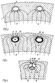
- the arrows A in Fig. 3 illustrate how the heat in a known embodiment of a cooling channel during the working of the engine flows from the inner surface of the liner to the annular space surrounding the tube. It will appear that the heat has a comparatively short distance of travel, thereby offering a high temperature gradient and thus a strong cooling. If a smaller cooling effect of the cooling channels is desired with one and the same cylinder liner, the cooling channels may instead be provided with a guide member according to the invention.
- FIG. 4 A cross-section through a cooling channel with such a guide member in the form of tube 21 is illustrated in Fig. 4.
- the tube has two radially projecting protuberances or ribs 30 extending in the longitudinal direction of the tube and having such a height that their free edge which may be smoothly rounded in order to diminish the stress concentrations in the liner, exactly abuts on the channel surface and divides the annular space surrounding the tube into two sections of which section 32 facing the inner surface of the liner (and marked in black) is provided with at least one barrier member designed as a horizontally positioned collar extending about the tube from the first to the second rib 30, thereby barring section 32 to prevent water flow.
- the coolant runs down towards chamber 7 through the second section 33 of the annular space and effects thus a cooling of the liner.
- the heat substantially is only conducted away in section 33, the heat has to travel a longer distance, as shown by arrows B, which, as stated above, results in less cooling.
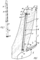
- the tube may alternatively in section 32 be provided with a material layer 34 extending from the external side of the tube to the channel surface, thereby causing the passage through section 32 to be blocked.
- This embodiment of the guide member is illustrated in more detail in Fig. 7.
- the material layer may be made from polytetra-fluoroethylene (PFTE) that is "self-lubrifying" when pushing the tube into the channel.
- PFTE polytetra-fluoroethylene
- the material layer may be adhered to the tube and/or fixed by means of a locking pin inserted in associated bores in the jacket and the tube.
- the jacket only covers part of the length of the tube and the upwards facing tube end may be jacket-free across a distance of 1 to 2 pipe diameters. Moreover, it is not a prerequisite of obtaining the reduced cooling of the liner aimed at by the invention that the jacket perfectly engages the internal side of the bore.
- Figs 5 and 6 illustrate a further embodiment according to the invention in which the coolant outlet chamber 7′ is positioned above a projecting flange 35 on the external side of the liner and in which a transverse hole 36 establishes connection between the cooling channel 8′ and chamber 7′.
- a guide member 38 is composed of three radially projecting protuberances or legs 39 that extend in the longitudinal direction of the channel and divides the channel into three sections of which the section 40 facing towards the inner surface of the liner at least at the top of the guide member and possibly also at its bottom is blocked by a barrier member in the form of a horizontally positioned plate member 41.
- the second section 42 is open at the top as well as at the bottom so that the coolant may flow upwards from chamber 6′ towards the blind end of the channel through said section, whereas the third section 43 is closed at the bottom by a horizontally positioned plate member 44, said section thereby constituting a return flow passage communicating through the transverse hole 36 with chamber 7′.
- the guide members 21, 38 may have a bypass hole 45 connecting chamber 6 with chamber 7.
- the bypass hole in tube 21 is on a level with chamber 7, while in the embodiment in Fig. 5 it is adjacent to the transverse hole 36.
- the bypass hole will pass part of the coolant, e.g. two thirds of the water, directly into -chamber 7 so that the use of the guide member according to the invention does not alter the quantity of coolant flowing through the cylinder frame.
- the ribs or legs may have the shape of a circular arc and the channel as well as the tube may have a non-circular cross-section, e.g. an oval cross-section.
- Plate members 41, 44 may have a collar that is shaped like a circular arc and abutting on the channel surface, or the plate members may have a comparatively large thickness in the longitudinal direction of the channel so that the plate members lean against the channel surface across such a large area that no considerable stress concentrations occur in the liner.
- the barrier member may also consist of a heat-resistant, water-insoluble and comparatively soft material, such as foam plastics, which in section 32 or 41 is fastened to the guide member.
Landscapes
- Engineering & Computer Science (AREA)
- Chemical & Material Sciences (AREA)
- Combustion & Propulsion (AREA)
- Mechanical Engineering (AREA)
- General Engineering & Computer Science (AREA)
- Cylinder Crankcases Of Internal Combustion Engines (AREA)
Abstract
Description
- The invention relates to a cylinder liner for a water-cooled combustion engine, in particular a two-stroke diesel engine, and with a cylindrical inner surface delimiting the combustion chamber of the engine and constituting a guide surface for a working piston coaxially journalled in the liner, which piston in its top dead centre position is adjacent to an upper end section of the liner, the upper end section containing a number of elongated cooling channels distributed along the circumference of the liner and being in communication with a coolant supply chamber and a coolant outlet chamber, each elongated cooling channel having an upwards extending blind end and a guide member mounted longitudinally within the channel and dividing the flow of water in the channel into a flow running upwardly towards the blind end of the channel and a flow running away from the blind end of the channel.
- In such a cylinder liner, known from DE-2 149 400, the cooling channels uppermost at the highly loaded top of the liner may be positioned close to the cylindrical inner surface, because the upwards extending blind end does not give rise to too high stress concentrations. The blind channels thus offer a good cooling of the thermally and mechanically highest loaded upper part of the liner.
- When the applied engine fuel is sulphurous which is inter alia the case with diesel engines run on heavy fuel oil, the temperature of the cylindrical inner surface of the liner must be controlled within a comparatively narrow interval which is restricted downwards by the wish to prevent sulphuric acid from condensing on the inner surface, and upwards with the view of impeding high-temperature damages to the structural material of the liner. Experience shows that the condensation of sulphuric acid resulting in intense corrosive wear both of the inner surface of the liner and of the piston proper may be avoided, if the temperature of the inner surface of the liner is kept at 200 to 230°C in the area adjacent to the upper piston ring when the piston is in its top dead centre position.
- If the cylinder liner is e.g. produced from cast iron the highest desirable surface temperature is about 350°C, because higher temperatures notoriously may entail lasting swelling of the cast iron material with subsequent crack formation.
- The need for cooling to control the temperature of the inner surface of the liner depends on the specified power for the engine. It is well known that an engine may be specified to a lower power (be derated) in order to obtain a better specific fuel consumption. This is obtained by maintaining the maximum pressure of the engine and, therefore, the lower limit of the allowable working temperature of the inner surface of the liner will not be altered. If the cooling in a derated engine is upheld on a level with that of an engine running at full rating, the temperature of the inner surface falls so much that the previously mentioned unwanted condensation of sulphuric acid may take place.
- US-A-2 572 392 deals with a cylinder liner cooled by means of a surrounding cooling chamber. The external side of the liner is provided with an insulation band in order to prevent acid from condensing on the inner surface of the liner adjacent the insulation.
- GB-B-2 019 490 relates to a cylinder liner whose upper end section comprises a series of continuous cooling channels, in which coolant is supplied at the lower end of the channel and discharged through a radially extending bore at the top of the channel. In order to impede acid condensation on the inner surface of the liner, an insulating tube of synthetic material is urged into the channel. The radially extending bores at the top of the channels make the liner unfitted for highly loaded uses.
- It is the object of the invention to provide a cylinder liner with blind bores in which the cooling effect of the blind bores may be altered according to requirement.
- With a view to this, the above mentioned cylinder liner according to the invention is characterized in that the guide member across part of the length of the channel substantially impedes the water flow at a section of the channel surface facing towards the combustion chamber, whereas at least one of the two flows running towards and away, respectively, from the blind end of the channel, is by the guide member forced to contact the section of the channel surface facing away from the combustion chamber.
- Due to the fact that the guide member prevents the water flow in the channel from flowing across and thus cool a section of the channel surface facing towards the combustion chamber, the heat flowing into the inner surface of the liner has to travel a longer distance through the liner in order to be delivered to the coolant. The longer distance results in a reduced temperature gradient and thus a higher temperature on the inner surface of the liner at unaltered coolant temperature and engine yield. Conversely, one and the same cylinder may be applied at different ratings (power lay-outs) of the engine by making use merely of guide members barring a section of the cooling channels appropriate for the actual engine power. Quite apart from the fact that this offers a standardizing advantage in the manufacture of the liners because, as regards a specific engine size, only one type of liner has to be manufactured and not a plurality of types dependent on the specified rating of the engine, the considerable advantage is obtained that an existing engine may be specified for a new rating without having to exchange the cylinder liners, merely the guide members have to be changed.
- In a particularly simple embodiment the guide member has at least two radially projecting ribs or legs extending in the longitudinal direction of the channel and whose free edge abuts on the channel surface, and the space defined by the ribs or legs and the channel surface faces towards the combustion chamber and is provided with a barrier member for interrupting the water flow. Since the free edges of the ribs or legs abut on the channel surface, they ensure the positioning of the guide member in the channel and at the same time the guide member is supported through a large part of its length which is particularly important in large engines in which the cooling channels and thus the guide members may have a length/diameter ratio typically amounting to 25. The cooling effect may be regulated according to desire in that the ribs or legs enclose between them a larger or smaller angle, thereby barring a larger or smaller section of the channel surface from the coolant.
- In an embodiment in which the guide member has three ribs defining, on one hand, the space that faces towards the combustion chamber and includes the barrier member and, on the other hand, two parallel flow passages facing away from the combustion chamber, the coolant may flow upwards through one of the two parallel flow passages and return through the other passage.
- In a preferred embodiment a uniform and effective cooling effect throughout the length of the channel is obtained in that the guide member is a tube with a smaller diameter than the channel and that the, at least two, radially projecting ribs or legs extend from the external side of the tube. An annular space is provided between the external side of the tube and the channel surface and when the coolant flows through a section of said space, the flow takes place as a film flow, thereby enhancing the coefficient of heat transfer by 200 to 400% in relation to the coolant flow in traditioal cooling channels, inter alia because the film flow impedes local boiling on the surface of the cooling channel which would entail a strong decrease in the local heat transfer.
- The coolant flow in the channel may also be barred from the section of the channel surface facing towards the combustion chamber by providing the tube in this section with a material layer extending substantially from the external side of the tube to the channel surface.
- Examples of embodiments of the invention will now be described in detail with reference to the schematical drawings, in which
- Fig. 1 is a cross-section through an engine cylinder with a cylinder liner according to the invention,
- Fig. 2 is an illustration of the upper end area of the cylinder liner in Fig. 1,
- Fig. 3 is a cross-section through a known embodiment of two cooling channels,
- Fig. 4 is a cross-section through two cooling channels according to the invention,
- Fig. 5 is a section through a second embodiment according to the invention,
- Fig. 6 is a cross-section through a cooling channel in the cylinder liner in Fig. 5, and
- Fig. 7 is a perspective view of a third embodiment of a guide member.
- The upper end section of a cylinder liner 1 in a large low-speed diesel engine is illustrated in Fig. 1, in which a
piston 2 is shown in its top dead centre position. The liner 1 is by a cylinder cover 3 tightened towards thecylinder frame 4. Anannular water jacket 5 surrounds the upper end section and defines together with the radial external side of the liner an annular lowercoolant supply chamber 6 and an annular upper coolant outlet chamber 7, designed as a circumferential groove in the external side of the liner. A number ofcooling channels 8 in the liner establishes flow connection between said two chambers. - During the working of the engine coolant from a cooling chamber that surrounds the lower end section of the liner flows through a drilled connecting
channel 10 and a connecting tube 11 into thelower chamber 6 and disperses around the circumference of the liner, following which the water viachannels 8 flows into the upper chamber 7. From said chamber the coolant is passed through aconnecting tube 14, a drilledchannel 15, adistribution chamber 16 and cooling channels 17 in the engine cover and further on to the cooling chamber 18 in the valve seat from which the coolant is carried off. - As shown in Fig. 2, the liner comprises a larger number of straight,
elongated cooling channels 8 uniformly distributed along the circumference. The substantially circular-cylindrical channels 8 are skewed in relation to the longitudinal axis of the liner and extend upwardly towards theupper edge portion 28 of the inner side of the liner. Theblind end 25 of the channel may be hemispherical in order to diminish stress concentrations. - From the external side of the liner the
cooling channels 8 are drilled into the upper end section. Awater supply tube 21 with a smaller diameter than the channel projects into said channel. For the sake of clearness a tube has only been shown in one of the channels. A projectingflange 22 at the lower tube end abuts on a shoulder in a projectingcollar 23 separating thechambers 6 and 7 from each other. Abushing 24 keeps the tube in sealing abutment on the shoulder, thereby forcing coolant fromchamber 6 to flow through the tube prior to its penetrating into thechannel 8. In view of the fact that the upper end of the tube terminates close to theblind end 25 of the channel, the coolant contacts the blind end as a concentrated jet, following which the water flows down into a section of the annular space between the external side of the tube and the channel surface, said section facing away from the inner surface of the liner. The water flows from the annular space down into chamber 7. - The arrows A in Fig. 3 illustrate how the heat in a known embodiment of a cooling channel during the working of the engine flows from the inner surface of the liner to the annular space surrounding the tube. It will appear that the heat has a comparatively short distance of travel, thereby offering a high temperature gradient and thus a strong cooling. If a smaller cooling effect of the cooling channels is desired with one and the same cylinder liner, the cooling channels may instead be provided with a guide member according to the invention.
- A cross-section through a cooling channel with such a guide member in the form of
tube 21 is illustrated in Fig. 4. The tube has two radially projecting protuberances orribs 30 extending in the longitudinal direction of the tube and having such a height that their free edge which may be smoothly rounded in order to diminish the stress concentrations in the liner, exactly abuts on the channel surface and divides the annular space surrounding the tube into two sections of whichsection 32 facing the inner surface of the liner (and marked in black) is provided with at least one barrier member designed as a horizontally positioned collar extending about the tube from the first to thesecond rib 30, thereby barringsection 32 to prevent water flow. The coolant runs down towards chamber 7 through thesecond section 33 of the annular space and effects thus a cooling of the liner. In view of the fact that the heat substantially is only conducted away insection 33, the heat has to travel a longer distance, as shown by arrows B, which, as stated above, results in less cooling. Instead of providing the tube withribs 30 the tube may alternatively insection 32 be provided with amaterial layer 34 extending from the external side of the tube to the channel surface, thereby causing the passage throughsection 32 to be blocked. This embodiment of the guide member is illustrated in more detail in Fig. 7. The material layer may be made from polytetra-fluoroethylene (PFTE) that is "self-lubrifying" when pushing the tube into the channel. The material layer may be adhered to the tube and/or fixed by means of a locking pin inserted in associated bores in the jacket and the tube. The jacket only covers part of the length of the tube and the upwards facing tube end may be jacket-free across a distance of 1 to 2 pipe diameters. Moreover, it is not a prerequisite of obtaining the reduced cooling of the liner aimed at by the invention that the jacket perfectly engages the internal side of the bore. - Figs 5 and 6 illustrate a further embodiment according to the invention in which the coolant outlet chamber 7′ is positioned above a projecting
flange 35 on the external side of the liner and in which atransverse hole 36 establishes connection between the coolingchannel 8′ and chamber 7′. Aguide member 38 is composed of three radially projecting protuberances orlegs 39 that extend in the longitudinal direction of the channel and divides the channel into three sections of which thesection 40 facing towards the inner surface of the liner at least at the top of the guide member and possibly also at its bottom is blocked by a barrier member in the form of a horizontally positionedplate member 41. Thesecond section 42 is open at the top as well as at the bottom so that the coolant may flow upwards fromchamber 6′ towards the blind end of the channel through said section, whereas thethird section 43 is closed at the bottom by a horizontally positionedplate member 44, said section thereby constituting a return flow passage communicating through thetransverse hole 36 with chamber 7′. - The
guide members bypass hole 45 connectingchamber 6 with chamber 7. In the embodiment illustrated in Figs 1 and 2, the bypass hole intube 21 is on a level with chamber 7, while in the embodiment in Fig. 5 it is adjacent to thetransverse hole 36. The bypass hole will pass part of the coolant, e.g. two thirds of the water, directly into -chamber 7 so that the use of the guide member according to the invention does not alter the quantity of coolant flowing through the cylinder frame. - The described embodiments may of course be modified in different ways. For example, the ribs or legs may have the shape of a circular arc and the channel as well as the tube may have a non-circular cross-section, e.g. an oval cross-section.
Plate members section
Claims (6)
- A cylinder liner (1; 1′) for a water-cooled combustion engine, in particular a two-stroke diesel engine, and with a cylindrical inner surface delimiting the combustion chamber of the engine and constituting a guide surface for a working piston (2; 2) coaxially journalled in the liner, which piston in its top dead centre position is adjacent to an upper end section of the liner, the upper end section containing a number of elongated cooling channels (8; 8′) distributed along the circumference of the liner and being in communication with a coolant supply chamber (6; 6′) and a coolant outlet chamber (7; 7), each elongated cooling channel having an upwards extending blind end (25; 25′) and a guide member (21; 38) mounted longitudinally within the channel and dividing the flow of water in the channel into a flow running upwardly towards the blind end of the channel and a flow running away from the blind end of the channel, characterized in that the guide member (21; 38) across part of the length of the channel substantially impedes the water flow at a section (32; 40) of the channel surface facing towards the combustion chamber, and that at least one of the two flows running towards and away, respectively, from the blind end of the channel (8; 8′) is forced by the guide member (21; 38) to contact the section (33; 42, 43) of the channel surface facing away from the combustion chamber.
- A cylinder liner as claimed in claim 1, characterized in that the guide member (21; 38) has at least two radially projecting ribs or legs (30; 39) extending in the longitudinal direction of the channel and whose free edge abuts on the channel surface, and that the space defined by the protuberances (30; 39) and the channel surface faces towards the combustion chamber and is provided with a barrier member (34; 41) for interrupting the water flow.
- A cylinder liner as claimed in claim 2, characterized in that the guide member (38) has three legs or ribs (39) defining, on one hand, the space that faces towards the combustion chamber and includes the barrier member (41) and, on the other hand, two parallel flow passages (42, 43) facing away from the combustion chamber.
- A cylinder liner as claimed in claim 2, characterized in that the guide member is a tube (21) having a smaller diameter than the channel (8) and that those, at least two, radially projecting protuberances or ribs (30) extend from the external side of the tube.
- A cylinder liner as claimed in any of the preceding claims, characterized in that the guide member is a tube (21) having a smaller diameter than the channel and which on the part of the external side of the tube facing towards the combustion chamber is provided with a material layer (34) substantially extending from the external side of the tube to the channel surface.
- A cylinder liner as claimed in any of the preceding claims, characterized in that the guide member (31; 38) has a bypass hole (45) positioned close to the coolant supply chamber (6) and establishing flow connection to the water outlet chamber.
Applications Claiming Priority (3)
| Application Number | Priority Date | Filing Date | Title |
|---|---|---|---|
| DK2776/90 | 1990-11-22 | ||
| DK277690A DK277690D0 (en) | 1990-11-22 | 1990-11-22 | CYLINDER LINING FOR A WATER-COOLED COMBUSTION ENGINE |
| PCT/DK1991/000348 WO1992009801A1 (en) | 1990-11-22 | 1991-11-21 | A cylinder liner for a water-cooled internal combustion engine |
Publications (2)
| Publication Number | Publication Date |
|---|---|
| EP0558583A1 EP0558583A1 (en) | 1993-09-08 |
| EP0558583B1 true EP0558583B1 (en) | 1994-06-22 |
Family
ID=8115653
Family Applications (1)
| Application Number | Title | Priority Date | Filing Date |
|---|---|---|---|
| EP91920598A Expired - Lifetime EP0558583B1 (en) | 1990-11-22 | 1991-11-21 | A cylinder liner for a water-cooled internal combustion engine |
Country Status (11)
| Country | Link |
|---|---|
| EP (1) | EP0558583B1 (en) |
| JP (1) | JP3142562B2 (en) |
| KR (1) | KR100233883B1 (en) |
| DE (1) | DE69102656T2 (en) |
| DK (2) | DK277690D0 (en) |
| ES (1) | ES2057923T3 (en) |
| PL (1) | PL167660B1 (en) |
| RO (1) | RO109675B1 (en) |
| RU (1) | RU2070297C1 (en) |
| UA (1) | UA25827C2 (en) |
| WO (1) | WO1992009801A1 (en) |
Cited By (1)
| Publication number | Priority date | Publication date | Assignee | Title |
|---|---|---|---|---|
| US12473871B2 (en) | 2024-02-15 | 2025-11-18 | Progress Rail Locomotive Inc. | Cylinder liner having coolant flow balancer and engine power assembly using same |
Families Citing this family (8)
| Publication number | Priority date | Publication date | Assignee | Title |
|---|---|---|---|---|
| DK170447B1 (en) * | 1993-05-26 | 1995-09-04 | Man B & W Diesel Gmbh | Process and internal combustion engine |
| DK173116B1 (en) * | 1996-05-07 | 2000-01-31 | Man B & W Diesel As | Cylinder liner for an internal combustion engine |
| DE19815919B4 (en) * | 1998-04-09 | 2004-04-15 | Man B & W Diesel A/S | Two-stroke engine |
| RU2194173C2 (en) * | 1999-04-19 | 2002-12-10 | Открытое акционерное общество Холдинговая компания "Барнаултрансмаш" | Liquid cooling system of internal combustion engine |
| RU2441991C2 (en) * | 2009-12-29 | 2012-02-10 | Государственное образовательное учреждение высшего профессионального образования Новгородский государственный университет имени Ярослава Мудрого | Piston engine combustion chamber |
| DK179175B1 (en) | 2016-03-16 | 2018-01-08 | Man Diesel & Turbo Filial Af Man Diesel & Turbo Se Tyskland | A cylinder cover for a large two-stroke turbocharged compression-ignited internal combustion engine |
| EP3219970A1 (en) * | 2016-03-17 | 2017-09-20 | Winterthur Gas & Diesel AG | Cylinder for a longitudinally wound two-stroke large disel engine and large diesel engine |
| CN109026428B (en) * | 2018-08-16 | 2020-12-22 | 全椒县全动机械有限公司 | An internal combustion engine top bank piston groove structure |
Family Cites Families (5)
| Publication number | Priority date | Publication date | Assignee | Title |
|---|---|---|---|---|
| US2572392A (en) | 1947-04-23 | 1951-10-23 | Caterpillar Tractor Co | Engine cooling, cylinder jacket, and head construction |
| DE2530736C3 (en) * | 1975-07-10 | 1984-06-28 | M.A.N. Maschinenfabrik Augsburg-Nürnberg AG, 8900 Augsburg | Thermally loaded component of an internal combustion engine with a hot wall |
| IT1055604B (en) * | 1975-08-27 | 1982-01-11 | Grandi Motori Trieste Spa | CYLINDER SHIRT WITH INTERNAL COOLING PIPES FOR INTERNAL COMBUSTION ALTERNATIVE ENGINES |
| CH615980A5 (en) * | 1976-12-15 | 1980-02-29 | Sulzer Ag | |
| CH627523A5 (en) * | 1978-04-25 | 1982-01-15 | Sulzer Ag | CYLINDER INSERT OF A RECIPROCATING ENGINE. |
-
1990
- 1990-11-22 DK DK277690A patent/DK277690D0/en not_active Application Discontinuation
-
1991
- 1991-11-21 ES ES91920598T patent/ES2057923T3/en not_active Expired - Lifetime
- 1991-11-21 UA UA94051465A patent/UA25827C2/en unknown
- 1991-11-21 RO RO93-00507A patent/RO109675B1/en unknown
- 1991-11-21 KR KR1019930701525A patent/KR100233883B1/en not_active Expired - Fee Related
- 1991-11-21 DK DK91920598.9T patent/DK0558583T3/en active
- 1991-11-21 WO PCT/DK1991/000348 patent/WO1992009801A1/en not_active Ceased
- 1991-11-21 DE DE69102656T patent/DE69102656T2/en not_active Expired - Lifetime
- 1991-11-21 PL PL91299314A patent/PL167660B1/en unknown
- 1991-11-21 EP EP91920598A patent/EP0558583B1/en not_active Expired - Lifetime
- 1991-11-21 JP JP03518659A patent/JP3142562B2/en not_active Expired - Lifetime
- 1991-11-21 RU RU9193004998A patent/RU2070297C1/en active
Cited By (1)
| Publication number | Priority date | Publication date | Assignee | Title |
|---|---|---|---|---|
| US12473871B2 (en) | 2024-02-15 | 2025-11-18 | Progress Rail Locomotive Inc. | Cylinder liner having coolant flow balancer and engine power assembly using same |
Also Published As
| Publication number | Publication date |
|---|---|
| KR930702604A (en) | 1993-09-09 |
| PL167660B1 (en) | 1995-10-31 |
| DE69102656T2 (en) | 1994-11-24 |
| RO109675B1 (en) | 1995-04-28 |
| DK277690D0 (en) | 1990-11-22 |
| ES2057923T3 (en) | 1994-10-16 |
| DE69102656D1 (en) | 1994-07-28 |
| DK0558583T3 (en) | 1994-09-26 |
| KR100233883B1 (en) | 1999-12-15 |
| RU2070297C1 (en) | 1996-12-10 |
| UA25827C2 (en) | 1999-02-26 |
| JPH06502705A (en) | 1994-03-24 |
| JP3142562B2 (en) | 2001-03-07 |
| EP0558583A1 (en) | 1993-09-08 |
| WO1992009801A1 (en) | 1992-06-11 |
Similar Documents
| Publication | Publication Date | Title |
|---|---|---|
| US7032547B2 (en) | Cylinder block cooling arrangement for multi-cylinder internal combustion engine | |
| US4109617A (en) | Controlled flow cooling system for low weight reciprocating engine | |
| EP1662129B1 (en) | Cooling structure of cylinder block | |
| US9341104B2 (en) | Impingement cooling of cylinders in opposed-piston engines | |
| US7000584B1 (en) | Thermally insulated cylinder liner | |
| US20170298860A1 (en) | Cooling structure of multi-cylinder engine | |
| US4175503A (en) | Method of making air engine housing | |
| JPS60182342A (en) | Fluid cooling type composite piston for internal combustion engine | |
| US4794884A (en) | Internal combustion engine with fluid-cooled cylinder liner | |
| JPS6346260B2 (en) | ||
| JP2008057546A (en) | Cooling mechanism for cylinder jacket of internal combustion engine | |
| KR102401326B1 (en) | Cylinder head | |
| US5299538A (en) | Internal combustion engine block having a cylinder liner shunt flow cooling system and method of cooling same | |
| KR101776756B1 (en) | Engine having water jacket | |
| WO1992009801A1 (en) | A cylinder liner for a water-cooled internal combustion engine | |
| US6167847B1 (en) | Cylinder liner for a liquid-cooled internal combustion engine | |
| US10113501B2 (en) | Cooling structure of engine | |
| US6363894B1 (en) | Diesel engine having a cylinder liner with improved cooling characteristics | |
| US5505167A (en) | Internal combustion engine block having a cylinder liner shunt flow cooling system and method of cooling same | |
| US4445486A (en) | Internal combustion engine | |
| US5176113A (en) | Cylinder liner | |
| US10174708B2 (en) | Cooling structure of multi-cylinder engine | |
| US20250198362A1 (en) | Profiled cover plate for a piston | |
| DK170447B1 (en) | Process and internal combustion engine | |
| JPH0141869Y2 (en) |
Legal Events
| Date | Code | Title | Description |
|---|---|---|---|
| PUAI | Public reference made under article 153(3) epc to a published international application that has entered the european phase |
Free format text: ORIGINAL CODE: 0009012 |
|
| 17P | Request for examination filed |
Effective date: 19930416 |
|
| AK | Designated contracting states |
Kind code of ref document: A1 Designated state(s): CH DE DK ES FR GB IT LI |
|
| 17Q | First examination report despatched |
Effective date: 19931020 |
|
| GRAA | (expected) grant |
Free format text: ORIGINAL CODE: 0009210 |
|
| AK | Designated contracting states |
Kind code of ref document: B1 Designated state(s): CH DE DK ES FR GB IT LI |
|
| REF | Corresponds to: |
Ref document number: 69102656 Country of ref document: DE Date of ref document: 19940728 |
|
| ITF | It: translation for a ep patent filed | ||
| REG | Reference to a national code |
Ref country code: DK Ref legal event code: T3 |
|
| REG | Reference to a national code |
Ref country code: ES Ref legal event code: FG2A Ref document number: 2057923 Country of ref document: ES Kind code of ref document: T3 |
|
| ET | Fr: translation filed | ||
| PLBE | No opposition filed within time limit |
Free format text: ORIGINAL CODE: 0009261 |
|
| STAA | Information on the status of an ep patent application or granted ep patent |
Free format text: STATUS: NO OPPOSITION FILED WITHIN TIME LIMIT |
|
| 26N | No opposition filed | ||
| REG | Reference to a national code |
Ref country code: GB Ref legal event code: IF02 |
|
| PGFP | Annual fee paid to national office [announced via postgrant information from national office to epo] |
Ref country code: FR Payment date: 20101130 Year of fee payment: 20 Ref country code: DK Payment date: 20101110 Year of fee payment: 20 |
|
| PGFP | Annual fee paid to national office [announced via postgrant information from national office to epo] |
Ref country code: DE Payment date: 20101119 Year of fee payment: 20 Ref country code: CH Payment date: 20101123 Year of fee payment: 20 |
|
| PGFP | Annual fee paid to national office [announced via postgrant information from national office to epo] |
Ref country code: IT Payment date: 20101126 Year of fee payment: 20 Ref country code: GB Payment date: 20101118 Year of fee payment: 20 |
|
| PGFP | Annual fee paid to national office [announced via postgrant information from national office to epo] |
Ref country code: ES Payment date: 20101124 Year of fee payment: 20 |
|
| REG | Reference to a national code |
Ref country code: DE Ref legal event code: R071 Ref document number: 69102656 Country of ref document: DE |
|
| REG | Reference to a national code |
Ref country code: DE Ref legal event code: R071 Ref document number: 69102656 Country of ref document: DE |
|
| REG | Reference to a national code |
Ref country code: CH Ref legal event code: PL |
|
| REG | Reference to a national code |
Ref country code: DK Ref legal event code: EUP |
|
| REG | Reference to a national code |
Ref country code: GB Ref legal event code: PE20 Expiry date: 20111120 |
|
| REG | Reference to a national code |
Ref country code: ES Ref legal event code: FD2A Effective date: 20120206 |
|
| PG25 | Lapsed in a contracting state [announced via postgrant information from national office to epo] |
Ref country code: GB Free format text: LAPSE BECAUSE OF EXPIRATION OF PROTECTION Effective date: 20111120 |
|
| PG25 | Lapsed in a contracting state [announced via postgrant information from national office to epo] |
Ref country code: ES Free format text: LAPSE BECAUSE OF EXPIRATION OF PROTECTION Effective date: 20111122 |
|
| PG25 | Lapsed in a contracting state [announced via postgrant information from national office to epo] |
Ref country code: DE Free format text: LAPSE BECAUSE OF EXPIRATION OF PROTECTION Effective date: 20111122 |