EP0558546B1 - Container supply caps - Google Patents
Container supply caps Download PDFInfo
- Publication number
- EP0558546B1 EP0558546B1 EP91919972A EP91919972A EP0558546B1 EP 0558546 B1 EP0558546 B1 EP 0558546B1 EP 91919972 A EP91919972 A EP 91919972A EP 91919972 A EP91919972 A EP 91919972A EP 0558546 B1 EP0558546 B1 EP 0558546B1
- Authority
- EP
- European Patent Office
- Prior art keywords
- container
- outlet
- supply
- connector body
- fluid
- Prior art date
- Legal status (The legal status is an assumption and is not a legal conclusion. Google has not performed a legal analysis and makes no representation as to the accuracy of the status listed.)
- Expired - Lifetime
Links
Images

Classifications
-
- B—PERFORMING OPERATIONS; TRANSPORTING
- B67—OPENING, CLOSING OR CLEANING BOTTLES, JARS OR SIMILAR CONTAINERS; LIQUID HANDLING
- B67D—DISPENSING, DELIVERING OR TRANSFERRING LIQUIDS, NOT OTHERWISE PROVIDED FOR
- B67D7/00—Apparatus or devices for transferring liquids from bulk storage containers or reservoirs into vehicles or into portable containers, e.g. for retail sale purposes
- B67D7/02—Apparatus or devices for transferring liquids from bulk storage containers or reservoirs into vehicles or into portable containers, e.g. for retail sale purposes for transferring liquids other than fuel or lubricants
- B67D7/0288—Container connection means
- B67D7/0294—Combined with valves
-
- A—HUMAN NECESSITIES
- A01—AGRICULTURE; FORESTRY; ANIMAL HUSBANDRY; HUNTING; TRAPPING; FISHING
- A01M—CATCHING, TRAPPING OR SCARING OF ANIMALS; APPARATUS FOR THE DESTRUCTION OF NOXIOUS ANIMALS OR NOXIOUS PLANTS
- A01M7/00—Special adaptations or arrangements of liquid-spraying apparatus for purposes covered by this subclass
- A01M7/0089—Regulating or controlling systems
- A01M7/0092—Adding active material
-
- B—PERFORMING OPERATIONS; TRANSPORTING
- B05—SPRAYING OR ATOMISING IN GENERAL; APPLYING FLUENT MATERIALS TO SURFACES, IN GENERAL
- B05B—SPRAYING APPARATUS; ATOMISING APPARATUS; NOZZLES
- B05B7/00—Spraying apparatus for discharge of liquids or other fluent materials from two or more sources, e.g. of liquid and air, of powder and gas
- B05B7/24—Spraying apparatus for discharge of liquids or other fluent materials from two or more sources, e.g. of liquid and air, of powder and gas with means, e.g. a container, for supplying liquid or other fluent material to a discharge device
- B05B7/26—Apparatus in which liquids or other fluent materials from different sources are brought together before entering the discharge device
- B05B7/28—Apparatus in which liquids or other fluent materials from different sources are brought together before entering the discharge device in which one liquid or other fluent material is fed or drawn through an orifice into a stream of a carrying fluid
- B05B7/30—Apparatus in which liquids or other fluent materials from different sources are brought together before entering the discharge device in which one liquid or other fluent material is fed or drawn through an orifice into a stream of a carrying fluid the first liquid or other fluent material being fed by gravity, or sucked into the carrying fluid
-
- B—PERFORMING OPERATIONS; TRANSPORTING
- B67—OPENING, CLOSING OR CLEANING BOTTLES, JARS OR SIMILAR CONTAINERS; LIQUID HANDLING
- B67B—APPLYING CLOSURE MEMBERS TO BOTTLES JARS, OR SIMILAR CONTAINERS; OPENING CLOSED CONTAINERS
- B67B7/00—Hand- or power-operated devices for opening closed containers
- B67B7/24—Hole-piercing devices
- B67B7/26—Hole-piercing devices combined with spouts
Definitions
- This invention relates to a closed chemical transfer device for agricultural chemicals and the like comprising a container having an outlet for containing a quantity of fluid, and a supply cap connected to the outlet so as to permit supply of a fluid from within the container to a supply conduit in a sealed manner when the container is inverted so that the outlet is at its bottom.
- WO 89/11219 discloses an agricultural sprayer system of a type which includes a reservoir for supplying a dilutant for mixing with a chemical concentrate, and a spray head for spraying a mixture of the dilutant and the concentrate.
- the concentrate is supplied in a container and requires to be diluted with the dilutant, generally water, prior to use, the container being subsequently rinsed out with dilutant.
- the system includes a cap and associated hose for attachment to the outlet of the container to permit supply of concentrate to the system in a sealed manner when the container is inverted so that the outlet is at its bottom.
- the known supply cap includes an outlet duct for supply of concentrate from within the container when the container is inverted, a valved inlet duct for the passage of air into the container during supply of concentrate through the outlet duct, and an associated float provided to ensure that, when the container is filled with rinsing solution, the valved inlet duct is closed off by the float when the level of solution reaches the height of the float in the container.
- an arrangement is complicated in construction and does not completely obviate the hazard to the operator due to possible concentrate spillage when the cap is being fitted to the container after removal of the closure with which the container is supplied.
- EP 0389191 A1 discloses a device for the pressurised dispensing of beer and other beverages from a container in such a manner as to prevent the beverage in the container from coming into contact with air at any stage until it is dispensed.
- the beer is contained within a flexible inner bag within the container, and is dispensed through a valved outlet by introducing pressurised gas or air into the space between the inner bag and the outer container by way of a valved inlet, so as to apply pressure to the bag to expel the beverage from the bag through the container outlet.
- Such a pressurised system relies for its correct operation on the separation of the pressurised gas from the beverage by means of the bag.
- a closed chemical transfer device for agricultural chemicals and the like comprising a container having an outlet for containing a quantity of fluid, and a supply cap connected to the outlet so as to permit supply of fluid under the action of gravity and without the application of pressure from within the container to a supply conduit in a sealed manner when the container is inverted so that the outlet is at its bottom
- the supply cap including a connector body which is sealingly engaged with the outlet, an outlet duct extending through the connector body so as to be in fluid communication with the fluid within the container and provided for the passage of fluid out of the container when the container is inverted, and an inlet duct extending through the connector body so as to be in fluid communication with the fluid within the container and provided for the passage of air and/or rinsing liquid into the container to displace fluid supplied by way of the outlet duct whilst preventing the escape of fluid to atmosphere
- the supply cap includes coupling means mounted on the connector body for sealingly coupling the outlet duct to the supply conduit such that, when the supply conduit
- the connector body is provided with closure opening means for providing access through a closure member closing off the outlet when the connector body is engaged with the outlet on connection of the supply cap to the container so as to permit communication of the outlet duct with the inside of the container.
- closure opening means may be constituted by perforating means, such as a cutting edge, or alternatively it may simply comprise a displacing rod for opening a valve constituting the closure member.
- the supply cap 1 is adapted for fitting to the screwthreaded outlet 2 of a standard plastics container 3 for containing a chemical concentrate which, when diluted, is used for agricultural spraying.
- the outlet 2 has an upstanding rim 4 having an external screwthread 5 for receiving an internally screwthreaded cap (not shown) for closing off the outlet 2 when the container 3 is supplied to the user.
- a foil membrane 6, shown in broken lines in Figure 1 is secured to the rim 4 about its periphery so as to seal the outlet 2.
- the supply cap 1 is fitted to the outlet 2, after removal of the internally screwthreaded cap, by engaging an internally screwthreaded ring 7 of the supply cap 1 with the rim 4 and by rotating the ring 7 relative to the body 8 of the supply cap 1, so as to engage the internal screwthread 9 of the ring 7 with the external screwthread 5 of the rim 4 and so as to trap a sealing ring 9B between a shoulder 9A on the cap body 8 and the top of the rim 4.
- a perforating cutting flange 10 having a curved knife edge 11 (as best seen in Figures 3 and 4) integral with the body 8 perforates the foil membrane 6 so as to provide access to the inside of the container 3.
- the cap body 8 comprises a circular member 12 defining the shoulder 9A at its periphery and having an outlet duct 13 and an inlet duct 14 extending therethrough and integral therewith.
- the outlet duct 13 is provided for supply of chemical concentrate from within the container 3 to a supply conduit constituted by a flexible hose 15 when the container 3 is inverted.
- the outlet duct 13 has an external screwthread 16 externally of the cap for attachment of a dry break coupling part 17 and does not extend internally of the cap beyond the circular member 12.
- the inlet duct 14 is provided to admit air to the container along an inlet conduit constituted by a flexible hose 19A to displace chemical concentrate discharged through the outlet duct 13 when the container is inverted, and also to admit rinsing liquid to the container after the container has been emptied with a view to flushing out any chemical concentrate still remaining in the container.
- the inlet duct 14 has an external screwthread 18 externally of the cap for connection of a dry break coupling part 19. Furthermore the inlet duct 14 extends beyond the circular member 12 internally of the cap and is provided with an external screwthread 20 internally of the cap for detachable connection of a nozzle part 21.
- a strut 22 comprising a portion 23, as best seen in Figure 3, extending perpendicularly to the circular member 12 and an inclined portion 24 which extends across the internal opening of the outlet duct 13, as best seen in Figure 2, but which does not obstruct the opening.
- the strut 22 acts to fold the foil membrane 6 out of the way on perforation of this membrane by the cutting flange 10 so that the membrane does not obstruct the outlet duct 13.
- the nozzle part 21 comprises an internally screwthreaded sleeve 25 for fitting to the external screwthread 20 of the inlet duct 14, and three replaceable nozzles 26, 27 and 28 (see Figure 4) which extend through screwthreaded apertures in the walls of the sleeve 25.
- the nozzle 26 extends through the end wall of the sleeve 25 and is adapted to spray rinsing liquid over a conical angle of 90°
- the nozzles 27 and 28 extend through the side wall of the sleeve 25 and are inclined at slight angles downwardly and adapted to spray rinsing liquid over a conical angle of 50°.
- the nozzles are adapted to be unscrewed by a special tool and to be replaced by nozzles having different spray angles, aperture sizes, etc., as may be required for different applications or for metering different cleaning fluids. If required, the complete nozzle part 21 may be removed from the inlet duct 14 and replaced by an alternative nozzle part having different nozzles and/or nozzle arrangements.
- each of the dry break coupling parts 17 and 19 comprises a respective internally screwthreaded sleeve 30 or 31 for fitting to the outlet duct 13 or inlet duct 14 and a respective snap connector part 32 or 33 for detachable connection to a complementary dry break coupling part 34 or 35 provided on the hose 15 or 19A.
- Each of the dry break couplers formed by the coupling parts 32 and 34 and the coupling parts 33 and 35 is of a known type as will be described briefly with reference to Figure 1A.
- the male coupling part 32 (or 33) has a body part 42 and a movable valve member 43 which is biased by a spring 44 so that, when disconnected from the female coupling part 34 (or 35), the valve member 43 is biased into engagement with the valve seat 45 formed on the inside of the body part 42 so as to prevent any leakage from the coupling part 32.
- the female coupling part 34 (or 35) has a body part 46 having an inner tubular part 47 which, when the connection is established with the male coupling part 32 (or 33), serves to displace the valve member 43 of the male coupling part inwardly against spring force so that fluid communication is established between the bore 48 of the tubular part 47 and an annular chamber 49 within the body part 42 by way of apertures 48A, the chamber 49 being in communication with the lower part of the coupler by means of axially extending bores (not shown) extending through the body part 42.
- the female coupling part also has an inner sealing sleeve 36 biased by a spring 37 such that, when the coupling parts are disconnected, the sleeve 36 closes off the apertures 48A in the tubular part 47 to prevent leakage from the female coupling part.
- the female coupling part is locked to the male coupling part by a locking ring 37A which is releasable from an annular groove in the body part 42 by movement of an outer sleeve 38 upwardly against the action of a spring 39.
- the dry break couplers are of different dimensions in order to prevent incorrect connection of the hoses.
- the outlet cap 1 is adapted to be used particularly for supplying chemical concentrate from the container 3 to a chemical concentrate metering device as disclosed in International Patent Publication No. WO 89/11219 for introducing a measured quantity of chemical concentrate into an agricultural sprayer system where it is diluted with water to form a spraying solution.
- a chemical concentrate metering device as disclosed in International Patent Publication No. WO 89/11219 for introducing a measured quantity of chemical concentrate into an agricultural sprayer system where it is diluted with water to form a spraying solution.
- the hoses 15 and 19A are connected to the outlet duct 13 and the inlet duct 14 respectively and the container 3 is inverted, preferably being held in this position on a stand.
- the metering device is then operated to draw chemical concentrate from inside the container 3 along the hose 15, whilst a 3-way valve to which the hose 19A is connected is placed in a position to permit introduction of ambient or varying pressure air along the hose 19A, along the inlet duct 14 and through the nozzles 26, 27 and 28 into the container 3.
- the hose 19A is preferably arranged so as to prevent siphoning of concentrate along the hose 19A by way of the inlet duct 14.
- the 3-way valve When the container 3 has been emptied the 3-way valve is moved to a position to permit admission of rinsing liquid or cleaning fluid along the hose 19A and through the inlet duct 14 and the nozzles 26, 27 and 28 into the container, the rinsing liquid subsequently being removed from the container 3 through the outlet duct 13 and the hose 15 if required.
- the inlet duct may include a non-return valve 40, as shown diagrammatically in broken lines in Figure 1, to permit passage of air and rinsing fluid into the container, but to prevent concentrate from passing through the inlet duct 14 to the hose 19A.
- the outlet duct 13 may be provided with a non-return valve 41, as shown diagrammatically in broken lines in Figure 1, in order to permit passage of concentrate out of the container, but to prevent concentrate from passing along the outlet duct 13 in the opposite direction.
- Figures 5 and 6 show two further forms of supply cap 50 and 60 which are not provided with a perforating cutting flange for providing access to the inside of the container 3, but which are instead intended to be ready fitted to the container (or possibly fitted to the container after opening of the container).
- the same parts are given the same reference numerals as in Figures 1 to 4.
- the supply cap 50 has dry break coupling parts 17 and 19 similar to those shown in Figure 1, except that in this case the parts 17 and 19 are integral with the outlet duct 13 and inlet duct 14 respectively which are in turn integral with the cap body 8.
- the cap body 8 has a peripheral shoulder 9A which rests on the rim 4 of the container outlet 2 and is sealed thereto by sonic welding or by an adhesive.
- the cap body 8 may be an interference fit on the outlet 2 or may even be integrally moulded thereon.
- the shoulder 9A may be secured to the rim 4 by being clamped thereon by an internally screwthreaded ring 7 (shown partially cut-away in Figure 5) which is held on the externally screwthreaded rim 4 with an adhesive interposed therebetween so that it may be removed only with difficulty.
- the outlet duct 13 is optionally formed with a dip tube 51, and the inlet duct 14 is optionally provided with a non-return valve 52 within a dip tube 53. Where such a non-return valve 52 is provided, the dry break coupling part 19 may be dispensed with if required.
- the supply cap 60 of Figure 6 is very similar to the supply cap 50 of Figure 5 except that it has a modified cap body 61 which is so formed as to cause the dry break coupling parts 17 and 19 to be recessed within the outlet rim 4. This permits an internally screwthreaded closure cap 62 (shown partly cut-away in Figure 6) to be fitted to the outlet rim 4 when the container is supplied for use and to be subsequently removed by unscrewing to enable access to be obtained to the coupling parts 17 and 19 of the supply cap 60.
- the above described supply caps may be adapted to supply liquid, granular or powder substances. Whilst the cap is designed primarily to protect the operator and the environment from spillage, vapour or dust contamination during the supply of such substances, it can equally as well be used in applications in which a substance to be supplied, such as a food substance, must be protected from contamination by the environment.
Landscapes
- Engineering & Computer Science (AREA)
- Mechanical Engineering (AREA)
- Life Sciences & Earth Sciences (AREA)
- Insects & Arthropods (AREA)
- Pest Control & Pesticides (AREA)
- Wood Science & Technology (AREA)
- Zoology (AREA)
- Environmental Sciences (AREA)
- Closures For Containers (AREA)
- Nozzles (AREA)
- Devices For Use In Laboratory Experiments (AREA)
- Closing Of Containers (AREA)
- Casting Or Compression Moulding Of Plastics Or The Like (AREA)
- Physical Or Chemical Processes And Apparatus (AREA)
- General Details Of Gearings (AREA)
- Table Devices Or Equipment (AREA)
Abstract
Description
- This invention relates to a closed chemical transfer device for agricultural chemicals and the like comprising a container having an outlet for containing a quantity of fluid, and a supply cap connected to the outlet so as to permit supply of a fluid from within the container to a supply conduit in a sealed manner when the container is inverted so that the outlet is at its bottom.
- There are many applications in which it is required to transfer a substance from a container, in which the substance is supplied, to a supply point of a system in which the substance is to be processed or used, without permitting spillage or contamination of the substance. This may either be because the substances themselves or associated fumes are hazardous to operating personnel, or because the substances, such as foodstuffs, are to be kept free from contamination from the outside.
- International Patent Publication No. WO 89/11219 discloses an agricultural sprayer system of a type which includes a reservoir for supplying a dilutant for mixing with a chemical concentrate, and a spray head for spraying a mixture of the dilutant and the concentrate. The concentrate is supplied in a container and requires to be diluted with the dilutant, generally water, prior to use, the container being subsequently rinsed out with dilutant. In order to obviate the hazard to the operator due to possible chemical concentrate spillage on transfer from the container to the sprayer system, the system includes a cap and associated hose for attachment to the outlet of the container to permit supply of concentrate to the system in a sealed manner when the container is inverted so that the outlet is at its bottom.
- The known supply cap includes an outlet duct for supply of concentrate from within the container when the container is inverted, a valved inlet duct for the passage of air into the container during supply of concentrate through the outlet duct, and an associated float provided to ensure that, when the container is filled with rinsing solution, the valved inlet duct is closed off by the float when the level of solution reaches the height of the float in the container. However such an arrangement is complicated in construction and does not completely obviate the hazard to the operator due to possible concentrate spillage when the cap is being fitted to the container after removal of the closure with which the container is supplied.
- EP 0389191 A1 discloses a device for the pressurised dispensing of beer and other beverages from a container in such a manner as to prevent the beverage in the container from coming into contact with air at any stage until it is dispensed. The beer is contained within a flexible inner bag within the container, and is dispensed through a valved outlet by introducing pressurised gas or air into the space between the inner bag and the outer container by way of a valved inlet, so as to apply pressure to the bag to expel the beverage from the bag through the container outlet. Such a pressurised system relies for its correct operation on the separation of the pressurised gas from the beverage by means of the bag.
- It is an object of the invention to provide an improved closed chemical transfer device for agricultural chemicals and the like.
- According to the present invention there is provided a closed chemical transfer device for agricultural chemicals and the like comprising a container having an outlet for containing a quantity of fluid, and a supply cap connected to the outlet so as to permit supply of fluid under the action of gravity and without the application of pressure from within the container to a supply conduit in a sealed manner when the container is inverted so that the outlet is at its bottom, the supply cap including a connector body which is sealingly engaged with the outlet, an outlet duct extending through the connector body so as to be in fluid communication with the fluid within the container and provided for the passage of fluid out of the container when the container is inverted, and an inlet duct extending through the connector body so as to be in fluid communication with the fluid within the container and provided for the passage of air and/or rinsing liquid into the container to displace fluid supplied by way of the outlet duct whilst preventing the escape of fluid to atmosphere, characterised in that the supply cap includes coupling means mounted on the connector body for sealingly coupling the outlet duct to the supply conduit such that, when the supply conduit is connected to the coupling means, supply of fluid from the outlet duct to the supply conduit under the action of gravity and without the application of pressure when the container is inverted is permitted, whereas, when the supply conduit is disconnected from the coupling means, the outlet duct is closed off.
- In a preferred embodiment of the invention the connector body is provided with closure opening means for providing access through a closure member closing off the outlet when the connector body is engaged with the outlet on connection of the supply cap to the container so as to permit communication of the outlet duct with the inside of the container. In use of such an arrangement there is no need to remove a closure member, such as a membrane seal, with which the container may be supplied, prior to fitting of the supply cap to the outlet. The closure opening means may be constituted by perforating means, such as a cutting edge, or alternatively it may simply comprise a displacing rod for opening a valve constituting the closure member.
- In order that the invention may be more fully understood, several forms of device in accordance with the invention will now be described, by way of example, with reference to the accompanying drawings, in which:
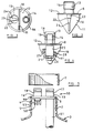
- Figure 1 is a section through a first supply cap for fitting to a container outlet;
- Figure 1A is a section through a first supply cap for fitting to a container outlet;
- Figure 2 is a view of the underneath of the first supply cap with a fitting ring and a nozzle part removed;
- Figures 3 and 4 are side views of the first supply cap, with the fitting ring removed, taken respectively in the directions of the arrows III and IV in Figure 1; and
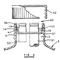
- Figures 5 and 6 are sections through second and third supply caps fitted to container outlets.
- Referring to Figure 1, the
supply cap 1 is adapted for fitting to the screwthreadedoutlet 2 of astandard plastics container 3 for containing a chemical concentrate which, when diluted, is used for agricultural spraying. Theoutlet 2 has anupstanding rim 4 having anexternal screwthread 5 for receiving an internally screwthreaded cap (not shown) for closing off theoutlet 2 when thecontainer 3 is supplied to the user. As an additional seal to prevent leakage of the chemical concentrate from thecontainer 3 during storage, afoil membrane 6, shown in broken lines in Figure 1, is secured to therim 4 about its periphery so as to seal theoutlet 2. - The
supply cap 1 is fitted to theoutlet 2, after removal of the internally screwthreaded cap, by engaging an internallyscrewthreaded ring 7 of thesupply cap 1 with therim 4 and by rotating thering 7 relative to thebody 8 of thesupply cap 1, so as to engage theinternal screwthread 9 of thering 7 with theexternal screwthread 5 of therim 4 and so as to trap asealing ring 9B between ashoulder 9A on thecap body 8 and the top of therim 4. During fitting of thesupply cap 1 to the outlet 2 a perforatingcutting flange 10 having a curved knife edge 11 (as best seen in Figures 3 and 4) integral with thebody 8 perforates thefoil membrane 6 so as to provide access to the inside of thecontainer 3. - The
cap body 8 comprises acircular member 12 defining theshoulder 9A at its periphery and having anoutlet duct 13 and aninlet duct 14 extending therethrough and integral therewith. Theoutlet duct 13 is provided for supply of chemical concentrate from within thecontainer 3 to a supply conduit constituted by aflexible hose 15 when thecontainer 3 is inverted. Theoutlet duct 13 has anexternal screwthread 16 externally of the cap for attachment of a drybreak coupling part 17 and does not extend internally of the cap beyond thecircular member 12. Theinlet duct 14 is provided to admit air to the container along an inlet conduit constituted by aflexible hose 19A to displace chemical concentrate discharged through theoutlet duct 13 when the container is inverted, and also to admit rinsing liquid to the container after the container has been emptied with a view to flushing out any chemical concentrate still remaining in the container. Theinlet duct 14 has anexternal screwthread 18 externally of the cap for connection of a drybreak coupling part 19. Furthermore theinlet duct 14 extends beyond thecircular member 12 internally of the cap and is provided with anexternal screwthread 20 internally of the cap for detachable connection of anozzle part 21. - Extending between the
circular member 12 and thecutting flange 10 is astrut 22 comprising aportion 23, as best seen in Figure 3, extending perpendicularly to thecircular member 12 and aninclined portion 24 which extends across the internal opening of theoutlet duct 13, as best seen in Figure 2, but which does not obstruct the opening. As well as providing lateral support to thecutting flange 10, thestrut 22 acts to fold thefoil membrane 6 out of the way on perforation of this membrane by thecutting flange 10 so that the membrane does not obstruct theoutlet duct 13. - The
nozzle part 21 comprises an internallyscrewthreaded sleeve 25 for fitting to theexternal screwthread 20 of theinlet duct 14, and threereplaceable nozzles sleeve 25. Thenozzle 26 extends through the end wall of thesleeve 25 and is adapted to spray rinsing liquid over a conical angle of 90°, whereas thenozzles sleeve 25 and are inclined at slight angles downwardly and adapted to spray rinsing liquid over a conical angle of 50°. The nozzles are adapted to be unscrewed by a special tool and to be replaced by nozzles having different spray angles, aperture sizes, etc., as may be required for different applications or for metering different cleaning fluids. If required, thecomplete nozzle part 21 may be removed from theinlet duct 14 and replaced by an alternative nozzle part having different nozzles and/or nozzle arrangements. - It will be appreciated that the
ring 7 and the drybreak coupling parts nozzle part 21 is additionally omitted in Figure 2. - Referring to Figure 1, each of the dry
break coupling parts screwthreaded sleeve outlet duct 13 orinlet duct 14 and a respectivesnap connector part break coupling part hose coupling parts coupling parts body part 42 and amovable valve member 43 which is biased by a spring 44 so that, when disconnected from the female coupling part 34 (or 35), thevalve member 43 is biased into engagement with thevalve seat 45 formed on the inside of thebody part 42 so as to prevent any leakage from thecoupling part 32. The female coupling part 34 (or 35) has abody part 46 having an innertubular part 47 which, when the connection is established with the male coupling part 32 (or 33), serves to displace thevalve member 43 of the male coupling part inwardly against spring force so that fluid communication is established between thebore 48 of thetubular part 47 and anannular chamber 49 within thebody part 42 by way ofapertures 48A, thechamber 49 being in communication with the lower part of the coupler by means of axially extending bores (not shown) extending through thebody part 42. The female coupling part also has aninner sealing sleeve 36 biased by aspring 37 such that, when the coupling parts are disconnected, thesleeve 36 closes off theapertures 48A in thetubular part 47 to prevent leakage from the female coupling part. In addition the female coupling part is locked to the male coupling part by a locking ring 37A which is releasable from an annular groove in thebody part 42 by movement of anouter sleeve 38 upwardly against the action of aspring 39. The dry break couplers are of different dimensions in order to prevent incorrect connection of the hoses. - The
outlet cap 1 is adapted to be used particularly for supplying chemical concentrate from thecontainer 3 to a chemical concentrate metering device as disclosed in International Patent Publication No. WO 89/11219 for introducing a measured quantity of chemical concentrate into an agricultural sprayer system where it is diluted with water to form a spraying solution. In use in such an application, and after fitting of thesupply cap 1 to thecontainer outlet 2 in the manner already described, thehoses outlet duct 13 and theinlet duct 14 respectively and thecontainer 3 is inverted, preferably being held in this position on a stand. The metering device is then operated to draw chemical concentrate from inside thecontainer 3 along thehose 15, whilst a 3-way valve to which thehose 19A is connected is placed in a position to permit introduction of ambient or varying pressure air along thehose 19A, along theinlet duct 14 and through thenozzles container 3. Thehose 19A is preferably arranged so as to prevent siphoning of concentrate along thehose 19A by way of theinlet duct 14. When thecontainer 3 has been emptied the 3-way valve is moved to a position to permit admission of rinsing liquid or cleaning fluid along thehose 19A and through theinlet duct 14 and thenozzles container 3 through theoutlet duct 13 and thehose 15 if required. - If appropriate for a particular application, the inlet duct may include a
non-return valve 40, as shown diagrammatically in broken lines in Figure 1, to permit passage of air and rinsing fluid into the container, but to prevent concentrate from passing through theinlet duct 14 to thehose 19A. Furthermore theoutlet duct 13 may be provided with anon-return valve 41, as shown diagrammatically in broken lines in Figure 1, in order to permit passage of concentrate out of the container, but to prevent concentrate from passing along theoutlet duct 13 in the opposite direction. - Figures 5 and 6 show two further forms of
supply cap container 3, but which are instead intended to be ready fitted to the container (or possibly fitted to the container after opening of the container). In Figures 5 and 6 the same parts are given the same reference numerals as in Figures 1 to 4. - Referring to Figure 5, the
supply cap 50 has drybreak coupling parts parts outlet duct 13 andinlet duct 14 respectively which are in turn integral with thecap body 8. Thecap body 8 has aperipheral shoulder 9A which rests on therim 4 of thecontainer outlet 2 and is sealed thereto by sonic welding or by an adhesive. In a variant of the illustrated arrangement thecap body 8 may be an interference fit on theoutlet 2 or may even be integrally moulded thereon. Alternatively theshoulder 9A may be secured to therim 4 by being clamped thereon by an internally screwthreaded ring 7 (shown partially cut-away in Figure 5) which is held on the externally screwthreadedrim 4 with an adhesive interposed therebetween so that it may be removed only with difficulty. Theoutlet duct 13 is optionally formed with adip tube 51, and theinlet duct 14 is optionally provided with anon-return valve 52 within adip tube 53. Where such anon-return valve 52 is provided, the drybreak coupling part 19 may be dispensed with if required. - The
supply cap 60 of Figure 6 is very similar to thesupply cap 50 of Figure 5 except that it has a modifiedcap body 61 which is so formed as to cause the drybreak coupling parts outlet rim 4. This permits an internally screwthreaded closure cap 62 (shown partly cut-away in Figure 6) to be fitted to theoutlet rim 4 when the container is supplied for use and to be subsequently removed by unscrewing to enable access to be obtained to thecoupling parts supply cap 60. - The above described supply caps may be adapted to supply liquid, granular or powder substances. Whilst the cap is designed primarily to protect the operator and the environment from spillage, vapour or dust contamination during the supply of such substances, it can equally as well be used in applications in which a substance to be supplied, such as a food substance, must be protected from contamination by the environment.
Claims (10)
- A closed chemical transfer device for agricultural chemicals and the like comprising a container (3) having an outlet (2) for containing a quantity of fluid, and a supply cap (1) connected to the outlet (2) so as to permit supply of fluid under the action of gravity and without the application of pressure from within the container (3) to a supply conduit (15) in a sealed manner when the container is inverted so that the outlet is at its bottom, the supply cap (1) including a connector body (8) which is sealingly engaged with the outlet (2), an outlet duct (13) extending through the connector body (8) so as to be in fluid communication with the fluid within the container (3) and provided for the passage of fluid out of the container (3) when the container is inverted, and an inlet duct (14) extending through the connector body (8) so as to be in fluid communication with the fluid within the container (3) and provided for the passage of air and/or rinsing liquid into the container (3) to displace fluid supplied by way of the outlet duct (13) whilst preventing the escape of fluid to atmosphere, characterised in that the supply cap (1) includes coupling means (17) mounted on the connector body (8) for sealingly coupling the outlet duct (13) to the supply conduit (15) such that, when the supply conduit (15) is connected to the coupling means (17), supply of fluid from the outlet duct (13) to the supply conduit (15) under the action of gravity and without the application of pressure when the container is inverted is permitted, whereas, when the supply conduit (15) is disconnected from the coupling means (17), the outlet duct (13) is closed off.
- A device according to Claim 1, wherein the connector body (8) is provided with closure opening means (10) for providing access through a closure member (6) closing off the outlet (2) when the connector body (8) is engaged with the outlet (2) on connection of the supply cap (1) to the container (3) so as to permit communication of the outlet duct (13) with the inside of the container (3).
- A device according to Claim 2, wherein the closure opening means is constituted by a perforating flange (10) on the connector body (8) projecting in a direction such that the flange (10) enters the outlet (2) to perforate the closure member (6) when the supply cap (1) is connected to the container (3).
- A device according to Claim 1, 2 or 3, wherein an internally screwthreaded ring (7) is provided for sealingly engaging the connector body (8) with the outlet (2) by engaging the internal screwthread of the ring (7) with an external screwthread (5) on the container (3).
- A device according to Claim 1, wherein the connector body (8, 61) is ready fitted to the outlet (2) of the container (3) when it is supplied filled with a quantity of fluid so that the connector body cannot be removed or so that it is removable only with difficulty.
- A device according to any preceding claim, wherein the inlet duct (14) is provided with a non-return valve (40, 52) which permits passage of air and/or rinsing liquid into the container (3) but which prevents escape of the fluid within the container through the inlet duct (14).
- A device according to any preceding claim, wherein further coupling means (19) are mounted on the connector body (8) for sealingly coupling the inlet duct (14) to an air and/or rinsing liquid further conduit (19A) such that, when the further conduit (19A) is connected to the further coupling means (19), supply of air and/or rinsing liquid from the further conduit (19A) to the inlet duct (14) is permitted whereas, when the further conduit (19A) is disconnected from the further coupling means (19), the inlet duct (14) is closed off.
- A device according to Claim 7, wherein the coupling means (17) and the further coupling means (19) are of different dimensions in order to prevent incorrect connection of the two conduits (15, 19A).
- A device according to any preceding claim, wherein nozzle means (21) are connected to the inlet duct (14) for distributing rinsing liquid within the container (3) in the form of a spray.
- A device according to Claim 9, wherein the nozzle means (21) includes a plurality of replaceable nozzles (26, 27, 28) directed at different angles.
Applications Claiming Priority (3)
| Application Number | Priority Date | Filing Date | Title |
|---|---|---|---|
| GB909025265A GB9025265D0 (en) | 1990-11-20 | 1990-11-20 | Container supply caps |
| GB9025265 | 1990-11-20 | ||
| PCT/GB1991/002043 WO1992008548A1 (en) | 1990-11-20 | 1991-11-19 | Container supply caps |
Publications (2)
| Publication Number | Publication Date |
|---|---|
| EP0558546A1 EP0558546A1 (en) | 1993-09-08 |
| EP0558546B1 true EP0558546B1 (en) | 1997-08-27 |
Family
ID=10685707
Family Applications (1)
| Application Number | Title | Priority Date | Filing Date |
|---|---|---|---|
| EP91919972A Expired - Lifetime EP0558546B1 (en) | 1990-11-20 | 1991-11-19 | Container supply caps |
Country Status (7)
| Country | Link |
|---|---|
| EP (1) | EP0558546B1 (en) |
| AT (1) | ATE157328T1 (en) |
| AU (1) | AU652789B2 (en) |
| CA (1) | CA2095922A1 (en) |
| DE (1) | DE69127452D1 (en) |
| GB (1) | GB9025265D0 (en) |
| WO (1) | WO1992008548A1 (en) |
Families Citing this family (5)
| Publication number | Priority date | Publication date | Assignee | Title |
|---|---|---|---|---|
| GB9226624D0 (en) * | 1992-12-21 | 1993-02-17 | Diversey Eng Europ | Drum connection system |
| ZA964400B (en) * | 1995-06-12 | 1996-12-09 | Unilever Nv | Flexible walled container for tableted or pelleted ware washing detergents |
| GB2304060B (en) * | 1995-08-03 | 1998-09-23 | Benest Eng Ltd | Liquid dispensing method and apparatus |
| FR3026400B1 (en) | 2014-09-26 | 2016-10-07 | Exel Ind | <P> DEVICE FOR TRANSFERRING A LIQUID FROM A CAN TOWEL TO A WATERPROOF TANK </ P> |
| WO2019178646A1 (en) * | 2018-03-22 | 2019-09-26 | Astral Pool Australia Pty Ltd | Holding and extracting liquid |
Family Cites Families (5)
| Publication number | Priority date | Publication date | Assignee | Title |
|---|---|---|---|---|
| US2628850A (en) * | 1949-03-19 | 1953-02-17 | Donald V Summerville | Releasable conduit connection with automatic valving |
| US3211178A (en) * | 1961-07-24 | 1965-10-12 | Aeroquip Corp | Concentric coupling |
| US4023718A (en) * | 1974-04-04 | 1977-05-17 | Revlon-Realistic Professional Products, Inc. | Sealing and closure structure for a spray dispensing device |
| GB8812047D0 (en) * | 1988-05-21 | 1988-06-22 | Garnett R H | Improvements in/relating to chemical concentrate metering |
| GB8906409D0 (en) * | 1989-03-21 | 1989-05-04 | Lambrechts Nv | Container for liquids |
-
1990
- 1990-11-20 GB GB909025265A patent/GB9025265D0/en active Pending
-
1991
- 1991-11-19 WO PCT/GB1991/002043 patent/WO1992008548A1/en not_active Ceased
- 1991-11-19 AU AU89205/91A patent/AU652789B2/en not_active Ceased
- 1991-11-19 EP EP91919972A patent/EP0558546B1/en not_active Expired - Lifetime
- 1991-11-19 DE DE69127452T patent/DE69127452D1/en not_active Expired - Lifetime
- 1991-11-19 CA CA002095922A patent/CA2095922A1/en not_active Abandoned
- 1991-11-19 AT AT91919972T patent/ATE157328T1/en not_active IP Right Cessation
Also Published As
| Publication number | Publication date |
|---|---|
| EP0558546A1 (en) | 1993-09-08 |
| DE69127452D1 (en) | 1997-10-02 |
| AU652789B2 (en) | 1994-09-08 |
| AU8920591A (en) | 1992-06-11 |
| WO1992008548A1 (en) | 1992-05-29 |
| GB9025265D0 (en) | 1991-01-02 |
| ATE157328T1 (en) | 1997-09-15 |
| CA2095922A1 (en) | 1992-05-21 |
Similar Documents
| Publication | Publication Date | Title |
|---|---|---|
| US5465875A (en) | Closed transfer devices for agricultural chemicals and the like | |
| US5553748A (en) | Refillable liquid dispenser | |
| CA1319914C (en) | Self-pressurizing sprayer | |
| US5110011A (en) | Non-releasable spray head and dip tube assembly | |
| EP0731736B1 (en) | Dispensing system | |
| US9963279B2 (en) | Container for transporting and storing a liquid | |
| KR100377054B1 (en) | Two-part coupling structure that flows fluid upon connection and seals again when disconnected | |
| US20090289025A1 (en) | Child resistant concentrate cartridge and associated diluting and dispensing container | |
| EP0415961B1 (en) | Improvements in or relating to chemical supply devices | |
| US20160185494A1 (en) | Container for Transporting and Storing a Liquid | |
| US4702267A (en) | Pesticide rinser | |
| US4905871A (en) | Handling device for agricultural chemicals and the like | |
| EP0517388B1 (en) | Single use spray dispensing assembly | |
| EP3261944B1 (en) | Closed loop connector for dispensing systems | |
| AU641517B2 (en) | System for hermetically dispensing and diluting a concentrated chemical | |
| AU652789B2 (en) | Closed chemical transfer devices | |
| US5497813A (en) | Apparatus for opening sealed containers | |
| US20100019062A1 (en) | Tank sprayer with separate concentrate container | |
| WO2007056375A2 (en) | System for failsafe controlled dispensing of liquid material | |
| WO2013153356A1 (en) | Liquid dispensing system |
Legal Events
| Date | Code | Title | Description |
|---|---|---|---|
| PUAI | Public reference made under article 153(3) epc to a published international application that has entered the european phase |
Free format text: ORIGINAL CODE: 0009012 |
|
| 17P | Request for examination filed |
Effective date: 19930428 |
|
| AK | Designated contracting states |
Kind code of ref document: A1 Designated state(s): AT BE CH DE DK ES FR GB GR IT LI LU NL SE |
|
| 17Q | First examination report despatched |
Effective date: 19941007 |
|
| GRAG | Despatch of communication of intention to grant |
Free format text: ORIGINAL CODE: EPIDOS AGRA |
|
| GRAH | Despatch of communication of intention to grant a patent |
Free format text: ORIGINAL CODE: EPIDOS IGRA |
|
| GRAH | Despatch of communication of intention to grant a patent |
Free format text: ORIGINAL CODE: EPIDOS IGRA |
|
| GRAA | (expected) grant |
Free format text: ORIGINAL CODE: 0009210 |
|
| AK | Designated contracting states |
Kind code of ref document: B1 Designated state(s): AT BE CH DE DK ES FR GB GR IT LI LU NL SE |
|
| PG25 | Lapsed in a contracting state [announced via postgrant information from national office to epo] |
Ref country code: NL Free format text: LAPSE BECAUSE OF FAILURE TO SUBMIT A TRANSLATION OF THE DESCRIPTION OR TO PAY THE FEE WITHIN THE PRESCRIBED TIME-LIMIT Effective date: 19970827 Ref country code: IT Free format text: LAPSE BECAUSE OF FAILURE TO SUBMIT A TRANSLATION OF THE DESCRIPTION OR TO PAY THE FEE WITHIN THE PRE;WARNING: LAPSES OF ITALIAN PATENTS WITH EFFECTIVE DATE BEFORE 2007 MAY HAVE OCCURRED AT ANY TIME BEFORE 2007. THE CORRECT EFFECTIVE DATE MAY BE DIFFERENT FROM THE ONE RECORDED.SCRIBED TIME-LIMIT Effective date: 19970827 Ref country code: GR Free format text: LAPSE BECAUSE OF FAILURE TO SUBMIT A TRANSLATION OF THE DESCRIPTION OR TO PAY THE FEE WITHIN THE PRESCRIBED TIME-LIMIT Effective date: 19970827 Ref country code: LI Free format text: LAPSE BECAUSE OF FAILURE TO SUBMIT A TRANSLATION OF THE DESCRIPTION OR TO PAY THE FEE WITHIN THE PRESCRIBED TIME-LIMIT Effective date: 19970827 Ref country code: ES Free format text: THE PATENT HAS BEEN ANNULLED BY A DECISION OF A NATIONAL AUTHORITY Effective date: 19970827 Ref country code: AT Effective date: 19970827 Ref country code: FR Free format text: LAPSE BECAUSE OF FAILURE TO SUBMIT A TRANSLATION OF THE DESCRIPTION OR TO PAY THE FEE WITHIN THE PRESCRIBED TIME-LIMIT Effective date: 19970827 Ref country code: BE Effective date: 19970827 Ref country code: CH Free format text: LAPSE BECAUSE OF FAILURE TO SUBMIT A TRANSLATION OF THE DESCRIPTION OR TO PAY THE FEE WITHIN THE PRESCRIBED TIME-LIMIT Effective date: 19970827 Ref country code: DK Free format text: LAPSE BECAUSE OF NON-PAYMENT OF DUE FEES Effective date: 19970827 |
|
| REF | Corresponds to: |
Ref document number: 157328 Country of ref document: AT Date of ref document: 19970915 Kind code of ref document: T |
|
| REG | Reference to a national code |
Ref country code: CH Ref legal event code: EP |
|
| REF | Corresponds to: |
Ref document number: 69127452 Country of ref document: DE Date of ref document: 19971002 |
|
| PG25 | Lapsed in a contracting state [announced via postgrant information from national office to epo] |
Ref country code: LU Free format text: LAPSE BECAUSE OF NON-PAYMENT OF DUE FEES Effective date: 19971119 |
|
| PG25 | Lapsed in a contracting state [announced via postgrant information from national office to epo] |
Ref country code: SE Effective date: 19971127 |
|
| PG25 | Lapsed in a contracting state [announced via postgrant information from national office to epo] |
Ref country code: DE Effective date: 19971128 |
|
| EN | Fr: translation not filed | ||
| NLV1 | Nl: lapsed or annulled due to failure to fulfill the requirements of art. 29p and 29m of the patents act | ||
| REG | Reference to a national code |
Ref country code: CH Ref legal event code: PL |
|
| PLBE | No opposition filed within time limit |
Free format text: ORIGINAL CODE: 0009261 |
|
| STAA | Information on the status of an ep patent application or granted ep patent |
Free format text: STATUS: NO OPPOSITION FILED WITHIN TIME LIMIT |
|
| 26N | No opposition filed | ||
| PGFP | Annual fee paid to national office [announced via postgrant information from national office to epo] |
Ref country code: GB Payment date: 19981120 Year of fee payment: 8 |
|
| PG25 | Lapsed in a contracting state [announced via postgrant information from national office to epo] |
Ref country code: GB Free format text: LAPSE BECAUSE OF NON-PAYMENT OF DUE FEES Effective date: 19991119 |
|
| GBPC | Gb: european patent ceased through non-payment of renewal fee |
Effective date: 19991119 |