EP0558273B1 - Container provided with a closure for dispensing liquids - Google Patents
Container provided with a closure for dispensing liquids Download PDFInfo
- Publication number
- EP0558273B1 EP0558273B1 EP93301324A EP93301324A EP0558273B1 EP 0558273 B1 EP0558273 B1 EP 0558273B1 EP 93301324 A EP93301324 A EP 93301324A EP 93301324 A EP93301324 A EP 93301324A EP 0558273 B1 EP0558273 B1 EP 0558273B1
- Authority
- EP
- European Patent Office
- Prior art keywords
- closure
- container
- projection
- lugs
- skirt
- Prior art date
- Legal status (The legal status is an assumption and is not a legal conclusion. Google has not performed a legal analysis and makes no representation as to the accuracy of the status listed.)
- Expired - Lifetime
Links
- 239000007788 liquid Substances 0.000 title description 2
- 230000015572 biosynthetic process Effects 0.000 claims description 10
- 238000005755 formation reaction Methods 0.000 claims description 10
- 239000000047 product Substances 0.000 description 8
- 238000007789 sealing Methods 0.000 description 7
- 230000000295 complement effect Effects 0.000 description 4
- 229920003023 plastic Polymers 0.000 description 3
- 239000004033 plastic Substances 0.000 description 3
- 230000014759 maintenance of location Effects 0.000 description 2
- 239000000463 material Substances 0.000 description 2
- 230000004888 barrier function Effects 0.000 description 1
- 239000011324 bead Substances 0.000 description 1
- 239000012263 liquid product Substances 0.000 description 1
- 238000004519 manufacturing process Methods 0.000 description 1
- 238000000034 method Methods 0.000 description 1
- 238000012986 modification Methods 0.000 description 1
- 230000004048 modification Effects 0.000 description 1
- 238000000465 moulding Methods 0.000 description 1
Images

Classifications
-
- B—PERFORMING OPERATIONS; TRANSPORTING
- B65—CONVEYING; PACKING; STORING; HANDLING THIN OR FILAMENTARY MATERIAL
- B65D—CONTAINERS FOR STORAGE OR TRANSPORT OF ARTICLES OR MATERIALS, e.g. BAGS, BARRELS, BOTTLES, BOXES, CANS, CARTONS, CRATES, DRUMS, JARS, TANKS, HOPPERS, FORWARDING CONTAINERS; ACCESSORIES, CLOSURES, OR FITTINGS THEREFOR; PACKAGING ELEMENTS; PACKAGES
- B65D47/00—Closures with filling and discharging, or with discharging, devices
- B65D47/04—Closures with discharging devices other than pumps
- B65D47/20—Closures with discharging devices other than pumps comprising hand-operated members for controlling discharge
- B65D47/24—Closures with discharging devices other than pumps comprising hand-operated members for controlling discharge with poppet valves or lift valves, i.e. valves opening or closing a passageway by a relative motion substantially perpendicular to the plane of the seat
- B65D47/241—Closures with discharging devices other than pumps comprising hand-operated members for controlling discharge with poppet valves or lift valves, i.e. valves opening or closing a passageway by a relative motion substantially perpendicular to the plane of the seat the valve being opened or closed by actuating a cap-like element
- B65D47/242—Closures with discharging devices other than pumps comprising hand-operated members for controlling discharge with poppet valves or lift valves, i.e. valves opening or closing a passageway by a relative motion substantially perpendicular to the plane of the seat the valve being opened or closed by actuating a cap-like element moving helically
-
- B—PERFORMING OPERATIONS; TRANSPORTING
- B65—CONVEYING; PACKING; STORING; HANDLING THIN OR FILAMENTARY MATERIAL
- B65D—CONTAINERS FOR STORAGE OR TRANSPORT OF ARTICLES OR MATERIALS, e.g. BAGS, BARRELS, BOTTLES, BOXES, CANS, CARTONS, CRATES, DRUMS, JARS, TANKS, HOPPERS, FORWARDING CONTAINERS; ACCESSORIES, CLOSURES, OR FITTINGS THEREFOR; PACKAGING ELEMENTS; PACKAGES
- B65D2215/00—Child-proof means
- B65D2215/02—Child-proof means requiring the combination of simultaneous actions
Definitions
- This invention relates to container/closure combinations, in particular such combinations in which the closure is required to dispense a liquid product from the container which is typically a squeeze bottle.
- container/closure combinations of this kind will hereinafter be referred to as "dispensing container/closure combinations”.
- the closure In dispensing container/closure combinations it is known for the closure to be rotatable on the container between limiting angular positions.
- the container and closure have complementary screw thread formations, and the rotation of the closure accordingly enables it to be moved axially between a raised position (in relation to the container) at which a dispensing aperture of the closure is open and product can be dispensed, and a lowered position at which the aperture is closed and dispensing or leakage is prevented.
- the container usually includes a snap-fitted plug member which directs product to the aperture for dispensing, but which engages the closure internally so as to close off the aperture when dispensing is no longer required and the closure is accordingly turned to its lowered position.
- a dispensing closure of the kind described in the previous paragraph is featured in US patent specification No. 4358031.
- the closure disclosed there is made child-resistant by virtue of the fact that below its screw threads, i.e. remote from the dispensing aperture, the closure carries a pair of opposed inward projections in the form of lugs. These lugs engage complementary outward projections in the form of further lugs which are formed on the container neck to prevent rotational removal of the closure from the container unless the closure is deformed in such a way so as to allow the lugs of the closure and container to pass one another.
- a further feature of the closure of US-A-4358031 is an annular retention ring which is located on the inside of the closure above its screw threads. When the closure is raised by rotation this ring engages a free edge presented by the plug member of the closure. Light engagement of the retention ring and the plug member then provides a limit stop to opening movement of the closure. With more forceful engagement, however, the plug member is forced off the container neck, and is removable with the closure so that the container is fully opened for dispensing product.
- a child-resistant dispensing closure with a container
- the closure and container having cooperable thread formations adapted to move the closure axially on the container between raised and lowered positions when the closure is rotated, and stop means which determine the raised position of the closure
- the container including a plug member adapted for closing a dispensing aperture of the closure when the closure is in its lowered position but allowing dispensing of product through the aperture when the closure is raised
- the closure having a tubular skirt which for child-resistance is formed with an inward projection operable by engagement with an outward projection of the container to prevent movement of the closure from its lowered position and which is deformable to allow the inward projection thereon to pass the outward projection of the container and so allow closure movement towards its raised position
- the stop means comprise a first stop projection which is one of said projections on either one of the closure or the container and, on the other one of the and the container, a further stop projection which is spaced both axially and ang
- said first stop projection is an elongate fin, and the other projection and the further stop projection are first and second lugs respectively.
- further stop means are also provided for determining the lowered position of the closure on the container.
- These further stop means are preferably associated with the thread formations of the container and the closure.
- a child-resistant dispensing closure 10 is injection-moulded from a suitable plastics material to have inner and outer spaced and concentric tubular skirts 12, 14 which extend concentrically from an annular closure panel 16 at one end.
- the inner skirt 12 is somewhat shorter than the outer skirt 14 and is internally formed with a two-start screw thread 18.
- This screw thread is capable of engagement with a complementary two-start thread 20 formed on the neck 21 on the body 30 of a plastics container, typically a squeeze bottle.
- the two parts of the screw thread 20 are individually indicated in Figs. 1 and 2 by the reference numberals 20A, 20B.
- the closure has a generally frustoconical projecting boss 24 located on its centreline within the closure panel 16.
- a dispensing aperture 26 is formed at the centre of the boss, as can clearly be seen to the right of Figure 3.
- a plug member 28 which forms part of the container but which is injection-moulded from a suitable plastics material separately from the container body 30, is located within the closure. It has a projecting central position 32 with a closed end 34. When the closure is in its lowered position (i.e. as shown on the left hand side of Fig.3) this end is capable of making sealing engagement with the boss 24 so as to close the dispensing aperture 26 against escape of product. It will be seen that the cooperating sealing faces 36, 38 of the closure and the plug member are substantially cylindrical.
- annular shoulder 40 at the bottom end of the sealing face 38 ensures positive location of the sealing faces in the axial sense, by abutment with a corresponding interior shoulder 42 of the boss assisted by natural resilience of the plug member in particular.
- the central portion 32 of the plug member 28 is formed with a number (e.g. four) of large apertures 44 of which two are visible in Fig.3.
- the plug member comprises, in sequence, a first annular portion 46 joined to the central portion, a first cylindrical portion 48, a second annular portion 50, and a second cylindrical portion 52 which extends to the free edge 54 of the plug member.
- the first cylindrical portion 48 is arranged to make sealing engagement over a cylindrical interface with the bore 56 of the container neck as shown.
- the two cylindrical portions 48, 52 form an inverted annular channel within which the free top end of the container neck is located, the outer cylindrical portion serving to hold the plug member captive on the container body by snap-engagement of a bead 58 beneath a shoulder 60 on the container neck.
- the sealing engagement of the portion 48 of the plug member and the container neck prevents escape of product between the plug member and the container neck to the region of the screw threads 18, 20.
- Product escape to the screw thread region via the outside of the plug member (but within the dispensing aperture 26) is provided by a cylindrical spigot 62 which extends integrally from the underside of the closure panel 16 at its junction with the boss 24 and into sealing engagement with the inside surface of the cylindrical portion 48.
- the closure/container combination is of a child-resistant kind, and for that purpose the container neck 21 is formed with a pair of diametrically opposed, substantially rigid lugs 64 which are carried on an upper enlarged diameter portion 65 of the neck below the screw threads 20.
- each lug has a ramp face 66 and a generally radially directed stop face 68. The stop face is located at the trailing end of the lug in the direction in which the closure is screwed onto the container.
- the outer skirt 14 of the closure carries a pair of diametrically opposed elongate and flexible fins 70 which are located between the skirts 12, 14.
- the fins extend for substantially the length of the outer skirt, but stop short of the free edge of the outer skirt to leave a marginal end portion 72 from which the fins are lacking. When the closure is in its lowered (closed) position this end portion lies closely adjacent a lower enlarged diameter portion 73 of the container neck for the reasons to be discussed later.
- the form of the fins 70 in cross-section can be seen from Fig.4 from which it will be seen that they have a tapering base portion 74 at which they are integrally carried from the outer skirt, and a parallel-faced free edge portion 76 with a rounded free edge 78 capable of engaging the stop face 68 of a respective lug 64.
- the closure 10 is capable of being screwed onto the container neck 21 by a conventional capping machine.
- the plug member may be fitted to the container neck prior to the capping operation, or alternatively it may be pre-assembled to the closure, the capping operation then achieving the snap-engagement of the plug member on the container neck simultaneously with movement of the closure towards its lowered (closed) position.
- the closure As the closure is approaching its closed position its fins 70 come into engagement with the lugs 64 on the container neck and ride resiliently over their ramp faces 66 in succession until the closed position of the closure is reached.
- the thickness of the outer skirt is increased progressively in the direction of its free edge (See Fig.3). Also, the outer skirt at the pressure pads is made somewhat thicker than the remainder of the periphery of the outer skirt to give increased local rigidity in those regions.
- a stop 82 is formed on the container neck at the trailing end of each part 20A, 20B of its screw thread 20.
- Each stop provides a stop face 84 (Fig.2) for engagement by the stop face 85 (Fig.4) of a similar stop which is located at the trailing end of a respective part of the closure thread 18. Such engagement occurs a small angular distance after the fins 70 have passed their associated lugs 64 in readiness for providing child-resistance.
- the portion 65 of the container neck is formed with a pair of additional lugs 86 for cooperation with the fins 70.
- These additional lugs have substantially the same cross-sectional form as the lugs 64, likewise having a ramp face 88 and a stop face 90. As can be seen from Fig.4, they are diametrically opposed to one another and spaced angularly from the lugs 64.
- each fin will engage and ride over a respective one of the additional lugs and after a further 135° of angular movement will engage and ride over the lug 64 with which it is associated for child-resistance; after a further small movement further rotation will be halted by engagement of the stops 82 with the associated stop faces 85 on the closure as described in the previous paragraph.
- the additional lugs are extended (as shown) to the intersection of the portions 65, 73 of the container neck. Their bottom ends therefore terminate on the same radial plane as those of the lugs 64.
- Figs 2 and 4 show a pair of opposed, substantially plane and axially extending flats 92 which are formed in the upper and lower enlarged portions 65, 73 of the container neck.
- the enlarged neck portion 73 is cylindrical except at these flats, and is coincident with the cylindrical envelope of the apices of the lugs 64.
- the flats 92 are located at 90° to the child-resistant lugs 64, and lie beneath the pressure pads 80 when the closure is in its closed position. They then provide clearance sufficient to allow deformation of the outer skirt 14 to cause the fins to be moved radially clear of the lugs 64 as described above. However, in the rotary position of the closure at which the fins 70 lie adjacent the stop faces 90 of the additional lugs 86, the flats are no longer located beneath the pressure pads, and inward movement of the pressure pads to create ovality of skirt is substantially prevented by the close adjacence of the marginal end portion 72 of the skirt with the underlying cylindrical surface of the enlarged portion 73 of the container neck.
- the additional lugs accordingly provide an impassable barrier to movement in the open direction of the closure, at a position when the dispensing aperture 26 is open to a degree appropriate to the contents of the container and the method used for dispensing.
- the closure is restrained against unwanted movement in the closing direction by latching bumps 94 moulded on the container neck.
- the closure may be arranged to make screw-threaded engagement with the plug member, which for that purpose should be mounted in a non-rotary manner on the container body.
- two lugs are provided on the container body for engagement with an elongate fin on the closure, these or equivalent formations may be transposed if desired.
- a formation such as a lug or fin may be provided either on the container body or on the plug member.
- Applicants prefer for ease of manufacture that the screw thread and other formations required for engagement with the closure be located on the container body rather than on the plug member.
- the heights of the lugs 64, 86 on the container neck are related to the pitch of the screw threads 18, 20 so that the lugs individually engage the associated fin 70 at the same point along its length.
- this relationship is not essential; if desired, the lugs may be of such effective heights that they engage different points of the fin 70.
Landscapes
- Engineering & Computer Science (AREA)
- Mechanical Engineering (AREA)
- Closures For Containers (AREA)
- Seal Device For Vehicle (AREA)
- Medical Preparation Storing Or Oral Administration Devices (AREA)
Abstract
Description
- This invention relates to container/closure combinations, in particular such combinations in which the closure is required to dispense a liquid product from the container which is typically a squeeze bottle. For brevity, container/closure combinations of this kind will hereinafter be referred to as "dispensing container/closure combinations".
- In dispensing container/closure combinations it is known for the closure to be rotatable on the container between limiting angular positions. The container and closure have complementary screw thread formations, and the rotation of the closure accordingly enables it to be moved axially between a raised position (in relation to the container) at which a dispensing aperture of the closure is open and product can be dispensed, and a lowered position at which the aperture is closed and dispensing or leakage is prevented. To achieve the opening and closing of the aperture the container usually includes a snap-fitted plug member which directs product to the aperture for dispensing, but which engages the closure internally so as to close off the aperture when dispensing is no longer required and the closure is accordingly turned to its lowered position.
- A dispensing closure of the kind described in the previous paragraph is featured in US patent specification No. 4358031. The closure disclosed there is made child-resistant by virtue of the fact that below its screw threads, i.e. remote from the dispensing aperture, the closure carries a pair of opposed inward projections in the form of lugs. These lugs engage complementary outward projections in the form of further lugs which are formed on the container neck to prevent rotational removal of the closure from the container unless the closure is deformed in such a way so as to allow the lugs of the closure and container to pass one another.
- A further feature of the closure of US-A-4358031 is an annular retention ring which is located on the inside of the closure above its screw threads. When the closure is raised by rotation this ring engages a free edge presented by the plug member of the closure. Light engagement of the retention ring and the plug member then provides a limit stop to opening movement of the closure. With more forceful engagement, however, the plug member is forced off the container neck, and is removable with the closure so that the container is fully opened for dispensing product.
- It will therefore be understood that the limit stop to opening movement provided in US-A-4358031 can be overridden by use of increased opening torque. Moreover, the limit stop engagement occurs above the screw thread engagement of the closure and container, independantly of the lug engagement which occurs below the screw threads to provide child resistance as mentioned above.
- In accordance with the invention there is provided the combination of a child-resistant dispensing closure with a container, the closure and container having cooperable thread formations adapted to move the closure axially on the container between raised and lowered positions when the closure is rotated, and stop means which determine the raised position of the closure, the container including a plug member adapted for closing a dispensing aperture of the closure when the closure is in its lowered position but allowing dispensing of product through the aperture when the closure is raised, the closure having a tubular skirt which for child-resistance is formed with an inward projection operable by engagement with an outward projection of the container to prevent movement of the closure from its lowered position and which is deformable to allow the inward projection thereon to pass the outward projection of the container and so allow closure movement towards its raised position, characterised in that the stop means comprise a first stop projection which is one of said projections on either one of the closure or the container and, on the other one of the and the container, a further stop projection which is spaced both axially and angularly from the other projection thereon, deformation of the skirt such as would allow said first stop projection and the further stop projection to pass one another being prevented by close adjacency of the skirt and the container at the angular position of the skirt at which the stop means are effective.
- Preferably said first stop projection is an elongate fin, and the other projection and the further stop projection are first and second lugs respectively.
- Advantageously, further stop means are also provided for determining the lowered position of the closure on the container. These further stop means are preferably associated with the thread formations of the container and the closure.
- In order that the invention may be more fully understood a dispensing closure/container combination in accordance with the invention will now be described by way of example and with reference to the accompanying drawings, in which:-
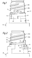
- Fig.1 is a view in side elevation showing the neck of the container body;
- Fig.2 is a view of the container neck as seen looking in the direction of the arrow A in Fig.1;
- Fig.3 is a view taken generally in central vertical section of the container neck with the plug member and closure fitted thereon, the container neck having the orientation shown in Fig.2; and
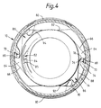
- Fig.4 is a sectional view of the assembly shown in Fig.3, taken on the radial plane IV - IV of that Figure.
- Referring now to the drawings, a child-
resistant dispensing closure 10 is injection-moulded from a suitable plastics material to have inner and outer spaced and concentrictubular skirts annular closure panel 16 at one end. Theinner skirt 12 is somewhat shorter than theouter skirt 14 and is internally formed with a two-start screw thread 18. This screw thread is capable of engagement with a complementary two-start thread 20 formed on theneck 21 on thebody 30 of a plastics container, typically a squeeze bottle. The two parts of thescrew thread 20 are individually indicated in Figs. 1 and 2 by thereference numberals - As shown in Fig.3, the closure has a generally
frustoconical projecting boss 24 located on its centreline within theclosure panel 16. A dispensingaperture 26 is formed at the centre of the boss, as can clearly be seen to the right of Figure 3. - A
plug member 28, which forms part of the container but which is injection-moulded from a suitable plastics material separately from thecontainer body 30, is located within the closure. It has a projectingcentral position 32 with a closedend 34. When the closure is in its lowered position (i.e. as shown on the left hand side of Fig.3) this end is capable of making sealing engagement with theboss 24 so as to close thedispensing aperture 26 against escape of product. It will be seen that the cooperating sealing faces 36, 38 of the closure and the plug member are substantially cylindrical. A small degree of interference between the faces ensures liquid tightness; also, anannular shoulder 40 at the bottom end of the sealingface 38 ensures positive location of the sealing faces in the axial sense, by abutment with a correspondinginterior shoulder 42 of the boss assisted by natural resilience of the plug member in particular. - To allow product from the
container body 30 to flow to thedispensing aperture 26 for dispensing thecentral portion 32 of theplug member 28 is formed with a number (e.g. four) oflarge apertures 44 of which two are visible in Fig.3. Other than the central portion the plug member comprises, in sequence, a firstannular portion 46 joined to the central portion, a first cylindrical portion 48, a secondannular portion 50, and a secondcylindrical portion 52 which extends to thefree edge 54 of the plug member. - The first cylindrical portion 48 is arranged to make sealing engagement over a cylindrical interface with the
bore 56 of the container neck as shown. The twocylindrical portions 48, 52 form an inverted annular channel within which the free top end of the container neck is located, the outer cylindrical portion serving to hold the plug member captive on the container body by snap-engagement of abead 58 beneath ashoulder 60 on the container neck. - The sealing engagement of the portion 48 of the plug member and the container neck prevents escape of product between the plug member and the container neck to the region of the
screw threads cylindrical spigot 62 which extends integrally from the underside of theclosure panel 16 at its junction with theboss 24 and into sealing engagement with the inside surface of the cylindrical portion 48. - The closure/container combination is of a child-resistant kind, and for that purpose the
container neck 21 is formed with a pair of diametrically opposed, substantiallyrigid lugs 64 which are carried on an upper enlargeddiameter portion 65 of the neck below thescrew threads 20. As clearly shown in Fig.4, each lug has aramp face 66 and a generally radially directedstop face 68. The stop face is located at the trailing end of the lug in the direction in which the closure is screwed onto the container. - For cooperation with the
lugs 64 theouter skirt 14 of the closure carries a pair of diametrically opposed elongate andflexible fins 70 which are located between theskirts marginal end portion 72 from which the fins are lacking. When the closure is in its lowered (closed) position this end portion lies closely adjacent a lower enlargeddiameter portion 73 of the container neck for the reasons to be discussed later. - The form of the
fins 70 in cross-section can be seen from Fig.4 from which it will be seen that they have a taperingbase portion 74 at which they are integrally carried from the outer skirt, and a parallel-facedfree edge portion 76 with a roundedfree edge 78 capable of engaging thestop face 68 of arespective lug 64. - The
closure 10 is capable of being screwed onto thecontainer neck 21 by a conventional capping machine. The plug member may be fitted to the container neck prior to the capping operation, or alternatively it may be pre-assembled to the closure, the capping operation then achieving the snap-engagement of the plug member on the container neck simultaneously with movement of the closure towards its lowered (closed) position. As the closure is approaching its closed position itsfins 70 come into engagement with thelugs 64 on the container neck and ride resiliently over their ramp faces 66 in succession until the closed position of the closure is reached. Engagement of the fins with the stop faces 68 of respective lugs will thereafter prevent movement of the closure from its closed position unless and until the fins are moved radially outwardly sufficiently to allow them to pass the lugs as the closure is unscrewed. This radial movement of the fins is achieved by ovality of theouter skirt 14 created by the user by pinching the outer skirt at a pair ofpressure pads 80 spaced by 90° from the fins. - In order to control the deformation and resilience of the
outer skirt 14 required for the closure to properly perform its child-resistant function, the thickness of the outer skirt is increased progressively in the direction of its free edge (See Fig.3). Also, the outer skirt at the pressure pads is made somewhat thicker than the remainder of the periphery of the outer skirt to give increased local rigidity in those regions. - In order to define accurately the closed position of the closure on the container and so prevent possible overscrewing, a
stop 82 is formed on the container neck at the trailing end of eachpart screw thread 20. Each stop provides a stop face 84 (Fig.2) for engagement by the stop face 85 (Fig.4) of a similar stop which is located at the trailing end of a respective part of theclosure thread 18. Such engagement occurs a small angular distance after thefins 70 have passed their associatedlugs 64 in readiness for providing child-resistance. - In addition to the pair of the
lugs 64 described above, theportion 65 of the container neck is formed with a pair ofadditional lugs 86 for cooperation with thefins 70. These additional lugs have substantially the same cross-sectional form as thelugs 64, likewise having aramp face 88 and astop face 90. As can be seen from Fig.4, they are diametrically opposed to one another and spaced angularly from thelugs 64. Their axial height on the container neck is greater than that of thelugs 64, and such that as the closure is being screwed onto the container by a capping machine, each fin will engage and ride over a respective one of the additional lugs and after a further 135° of angular movement will engage and ride over thelug 64 with which it is associated for child-resistance; after a further small movement further rotation will be halted by engagement of thestops 82 with the associated stop faces 85 on the closure as described in the previous paragraph. For ease of moulding, the additional lugs are extended (as shown) to the intersection of theportions lugs 64. - Reference is now made particularly to Figs 2 and 4, which show a pair of opposed, substantially plane and axially extending
flats 92 which are formed in the upper and lower enlargedportions enlarged neck portion 73 is cylindrical except at these flats, and is coincident with the cylindrical envelope of the apices of thelugs 64. - The
flats 92 are located at 90° to the child-resistant lugs 64, and lie beneath thepressure pads 80 when the closure is in its closed position. They then provide clearance sufficient to allow deformation of theouter skirt 14 to cause the fins to be moved radially clear of thelugs 64 as described above. However, in the rotary position of the closure at which thefins 70 lie adjacent the stop faces 90 of theadditional lugs 86, the flats are no longer located beneath the pressure pads, and inward movement of the pressure pads to create ovality of skirt is substantially prevented by the close adjacence of themarginal end portion 72 of the skirt with the underlying cylindrical surface of theenlarged portion 73 of the container neck. It will therefore be understood that under these circumstances deformation of the outer skirt adequate to enable the fins to clear the additional lugs is not possible; the additional lugs accordingly provide an impassable barrier to movement in the open direction of the closure, at a position when the dispensingaperture 26 is open to a degree appropriate to the contents of the container and the method used for dispensing. When in this position the closure is restrained against unwanted movement in the closing direction by latchingbumps 94 moulded on the container neck. - Many modifications and variations are possible within the scope of the present invention as defined by the appended claims. For example, instead of making screw threaded engagement with a complementary formation on the container body as described, the closure may be arranged to make screw-threaded engagement with the plug member, which for that purpose should be mounted in a non-rotary manner on the container body. Also, whilst in the described emodiment two lugs are provided on the container body for engagement with an elongate fin on the closure, these or equivalent formations may be transposed if desired. Moreover, a formation such as a lug or fin may be provided either on the container body or on the plug member. However, and as in the described embodiment, Applicants prefer for ease of manufacture that the screw thread and other formations required for engagement with the closure be located on the container body rather than on the plug member.
- Whilst the invention has been particularly described in relation to a closure having two skirts, it may also have application to closures/container combinations in which the closure has only a single skirt.
- In the described embodiment the heights of the
lugs screw threads fin 70 at the same point along its length. However, this relationship is not essential; if desired, the lugs may be of such effective heights that they engage different points of thefin 70.
Claims (9)
- The combination of a child-resistant dispensing closure with a container, the closure and container having cooperable thread formations (18,20) adapted to move the closure axially on the container between raised and lowered positions when the closure is rotated, and stop means which determine the raised position of the closure, the container including a plug member (28) adapted for closing a dispensing aperture of the closure when the closure is in its lowered position (26) but allowing dispensing of product through the aperture when the closure is raised, the closure having a tubular skirt (14) which for child-resistance is formed with an inward projection (70) operable by engagement with an outward projection (64) of the container to prevent movement of the closure from its lowered position and which is deformable to allow the inward projection thereon to pass the outward projection of the container and so allow closure movement towards its raised position, characterised in that the stop means comprise a first stop projection which is one of said projections on either one of the closure or the container and, on the other one of the closure and the container, a further stop projection (86) which is spaced both axially and angularly from the other projection thereon, deformation of the skirt such as would allow said first stop projection and the further stop projection (86) to pass one another being prevented by close adjacency of the skirt and the container at the angular position of the skirt at which the stop means are effective.
- A combination as claimed in claim 1, characterised in that said first stop projection is an elongate fin, and the other projection and the further stop projection, are first and second lugs respectively.
- A combination as claimed in any preceding claim, characterised by further stop means (84, 85) which determine the lowered position of the closure on the container.
- A combination as claimed in claim 3, characterised in that the further stop means are associated with the thread formations (18, 20) of the closure and the container.
- A combination as claimed in claim 2, characterised by latch means for latching the closure releasably in its open position, the latch means comprising a protrusion (94) on the container over which the fin (70), located on the closure, rides when approaching the lug forming the further projection (86).
- A combination as claimed in any preceding claim, characterised in that in order to allow the skirt to deform to allow the first said projection (70) to pass the other projection (64) the container is formed with a relieved face (92).
- A combination as claimed in claim 6, characterised in that the closure skirt (14) has a free end portion (72) at which it extends beyond the projection or projections thereon, the container having a portion (73) formed with the relieved face (92) and which except at the relieved face lies closely adjacent the free end portion of the skirt.
- A combination as claimed in claim 2, characterised in that the thread formations (18, 20) of the closure and container are two-start threads, the closure having a pair of said elongate fins (70) which are diametrically opposed, and the container correspondingly having diametrically opposed pairs of said first lugs (64) and said second lugs (86).
- A combination as claimed in claim 8, characterised in that each said first lug (64) is angularly spaced from the associated said second lug (86) by substantially 135°.
Applications Claiming Priority (2)
| Application Number | Priority Date | Filing Date | Title |
|---|---|---|---|
| GB9203980 | 1992-02-25 | ||
| GB929203980A GB9203980D0 (en) | 1992-02-25 | 1992-02-25 | Container/closure combinations |
Publications (2)
| Publication Number | Publication Date |
|---|---|
| EP0558273A1 EP0558273A1 (en) | 1993-09-01 |
| EP0558273B1 true EP0558273B1 (en) | 1995-11-08 |
Family
ID=10710993
Family Applications (1)
| Application Number | Title | Priority Date | Filing Date |
|---|---|---|---|
| EP93301324A Expired - Lifetime EP0558273B1 (en) | 1992-02-25 | 1993-02-23 | Container provided with a closure for dispensing liquids |
Country Status (5)
| Country | Link |
|---|---|
| EP (1) | EP0558273B1 (en) |
| AT (1) | ATE129977T1 (en) |
| DE (1) | DE69300747T2 (en) |
| GB (1) | GB9203980D0 (en) |
| ZA (1) | ZA931266B (en) |
Families Citing this family (7)
| Publication number | Priority date | Publication date | Assignee | Title |
|---|---|---|---|---|
| EP0690008A3 (en) * | 1994-07-01 | 1997-02-26 | Duering Ag | Threaded bottle closure |
| WO1998039228A1 (en) * | 1997-03-07 | 1998-09-11 | Rexam Plastics, Inc. | Edge dispensing closure with mating container |
| US6543650B1 (en) * | 2001-01-25 | 2003-04-08 | Rexam Medical Packaging Inc. | Double shell dispenser |
| US6698605B2 (en) | 2001-05-21 | 2004-03-02 | Rexam Medical Packaging Inc. | Modified bottle neck for use with child resistant caps |
| US6427881B1 (en) | 2001-10-09 | 2002-08-06 | Rexam Medical Packaging Inc. | Edge seal closure |
| IT1395158B1 (en) * | 2009-08-11 | 2012-09-05 | Gefit Spa | SPEAKER CAP FOR A BEVERAGE BOTTLE, IN PARTICULAR A BOTTLE OF ALCOHOLIC BEVERAGE |
| IT1403614B1 (en) * | 2010-12-22 | 2013-10-31 | Lumson Spa | SUPPLY DEVICE FOR FLUID SUBSTANCES, IN PARTICULAR CREAMS |
Family Cites Families (5)
| Publication number | Priority date | Publication date | Assignee | Title |
|---|---|---|---|---|
| US4116351A (en) * | 1974-06-03 | 1978-09-26 | Uhlig Gerhardt E | Safety closure container |
| US4358031A (en) * | 1980-08-26 | 1982-11-09 | Owens-Illinois, Inc. | Safety closure and container with dispensing spout |
| PT7818Y (en) * | 1986-10-22 | 1989-07-31 | Poltec Tecnologia De Transf De | THREAD COVER WITH LIMITED OPENING |
| US5038967A (en) * | 1989-08-22 | 1991-08-13 | W. Braun Company | Container with captive cap and internally valved closure |
| FR2660911B1 (en) * | 1990-04-13 | 1992-07-03 | Astra Plastique | CAPPING DEVICE WITH ROTATING CAP. |
-
1992
- 1992-02-25 GB GB929203980A patent/GB9203980D0/en active Pending
-
1993
- 1993-02-23 AT AT93301324T patent/ATE129977T1/en active
- 1993-02-23 DE DE69300747T patent/DE69300747T2/en not_active Expired - Lifetime
- 1993-02-23 ZA ZA931266A patent/ZA931266B/en unknown
- 1993-02-23 EP EP93301324A patent/EP0558273B1/en not_active Expired - Lifetime
Also Published As
| Publication number | Publication date |
|---|---|
| ZA931266B (en) | 1993-09-17 |
| ATE129977T1 (en) | 1995-11-15 |
| DE69300747T2 (en) | 1996-04-11 |
| GB9203980D0 (en) | 1992-04-08 |
| DE69300747D1 (en) | 1995-12-14 |
| EP0558273A1 (en) | 1993-09-01 |
Similar Documents
| Publication | Publication Date | Title |
|---|---|---|
| US4749103A (en) | Child resistant dispensing closure system | |
| US6135329A (en) | Universal base pull/push-twist closure | |
| US4781311A (en) | Angular positioned trigger sprayer with selective snap-screw container connection | |
| US6095375A (en) | Dust cover attachment for push-pull cap | |
| US6338425B1 (en) | Dispensing closure | |
| US6874664B1 (en) | Push-pull dispenser with folding fingers | |
| US6477743B1 (en) | Twist-openable dispensing closure accommodating optional liner puncture feature | |
| US5794803A (en) | Child-resistant measuring cup closure and dispensing container | |
| US6571994B1 (en) | Closure having rotatable spout and axially movable stem | |
| EP3950528B1 (en) | Capping device intended to be fixed on the neck of a container | |
| US6334555B1 (en) | Fitment and resealable dispensing closure assembly for high-pressure sealing and bi-modal dispensing | |
| US5197634A (en) | Side orifice dispensing closure | |
| US6299038B1 (en) | Telescoping twist closure | |
| USRE39727E1 (en) | Double shell dispenser | |
| US6062441A (en) | Two-piece dispensing closure | |
| EP0181115A2 (en) | Improvements in screw-topped containers | |
| US3934744A (en) | Closure assembly | |
| US4261487A (en) | Pour through stopper | |
| US5038967A (en) | Container with captive cap and internally valved closure | |
| US3168969A (en) | Off-center dispensing closure arrangement | |
| EP3842358B1 (en) | Capping device intended to be fixed to a neck of a container | |
| US5016787A (en) | Side orifice dispensing closure | |
| US4364492A (en) | Easy-dispensing safety cap | |
| US5110017A (en) | Container with captive cap and internally valved closure and positive closure seals | |
| GB2182027A (en) | Adjustable dispensing closure |
Legal Events
| Date | Code | Title | Description |
|---|---|---|---|
| PUAI | Public reference made under article 153(3) epc to a published international application that has entered the european phase |
Free format text: ORIGINAL CODE: 0009012 |
|
| AK | Designated contracting states |
Kind code of ref document: A1 Designated state(s): AT BE CH DE DK FR GB LI NL SE |
|
| 17P | Request for examination filed |
Effective date: 19940221 |
|
| 17Q | First examination report despatched |
Effective date: 19940325 |
|
| GRAA | (expected) grant |
Free format text: ORIGINAL CODE: 0009210 |
|
| RAP1 | Party data changed (applicant data changed or rights of an application transferred) |
Owner name: CARNAUDMETALBOX PLC |
|
| AK | Designated contracting states |
Kind code of ref document: B1 Designated state(s): AT BE CH DE DK FR GB LI NL SE |
|
| PG25 | Lapsed in a contracting state [announced via postgrant information from national office to epo] |
Ref country code: NL Free format text: LAPSE BECAUSE OF FAILURE TO SUBMIT A TRANSLATION OF THE DESCRIPTION OR TO PAY THE FEE WITHIN THE PRESCRIBED TIME-LIMIT Effective date: 19951108 Ref country code: LI Effective date: 19951108 Ref country code: DK Effective date: 19951108 Ref country code: CH Effective date: 19951108 Ref country code: BE Effective date: 19951108 Ref country code: AT Effective date: 19951108 |
|
| REF | Corresponds to: |
Ref document number: 129977 Country of ref document: AT Date of ref document: 19951115 Kind code of ref document: T |
|
| REF | Corresponds to: |
Ref document number: 69300747 Country of ref document: DE Date of ref document: 19951214 |
|
| ET | Fr: translation filed | ||
| PG25 | Lapsed in a contracting state [announced via postgrant information from national office to epo] |
Ref country code: SE Effective date: 19960208 |
|
| NLV1 | Nl: lapsed or annulled due to failure to fulfill the requirements of art. 29p and 29m of the patents act | ||
| REG | Reference to a national code |
Ref country code: CH Ref legal event code: PL |
|
| PLBE | No opposition filed within time limit |
Free format text: ORIGINAL CODE: 0009261 |
|
| STAA | Information on the status of an ep patent application or granted ep patent |
Free format text: STATUS: NO OPPOSITION FILED WITHIN TIME LIMIT |
|
| 26N | No opposition filed | ||
| REG | Reference to a national code |
Ref country code: GB Ref legal event code: IF02 |
|
| REG | Reference to a national code |
Ref country code: GB Ref legal event code: 732E |
|
| REG | Reference to a national code |
Ref country code: FR Ref legal event code: CD |
|
| PGFP | Annual fee paid to national office [announced via postgrant information from national office to epo] |
Ref country code: FR Payment date: 20100226 Year of fee payment: 18 |
|
| PGFP | Annual fee paid to national office [announced via postgrant information from national office to epo] |
Ref country code: GB Payment date: 20100218 Year of fee payment: 18 Ref country code: DE Payment date: 20100219 Year of fee payment: 18 |
|
| GBPC | Gb: european patent ceased through non-payment of renewal fee |
Effective date: 20110223 |
|
| REG | Reference to a national code |
Ref country code: FR Ref legal event code: ST Effective date: 20111102 |
|
| REG | Reference to a national code |
Ref country code: DE Ref legal event code: R119 Ref document number: 69300747 Country of ref document: DE Effective date: 20110901 |
|
| PG25 | Lapsed in a contracting state [announced via postgrant information from national office to epo] |
Ref country code: FR Free format text: LAPSE BECAUSE OF NON-PAYMENT OF DUE FEES Effective date: 20110228 |
|
| PG25 | Lapsed in a contracting state [announced via postgrant information from national office to epo] |
Ref country code: GB Free format text: LAPSE BECAUSE OF NON-PAYMENT OF DUE FEES Effective date: 20110223 |
|
| PG25 | Lapsed in a contracting state [announced via postgrant information from national office to epo] |
Ref country code: DE Free format text: LAPSE BECAUSE OF NON-PAYMENT OF DUE FEES Effective date: 20110901 |