EP0558017B1 - Contour restoration apparatus - Google Patents
Contour restoration apparatus Download PDFInfo
- Publication number
- EP0558017B1 EP0558017B1 EP93103006A EP93103006A EP0558017B1 EP 0558017 B1 EP0558017 B1 EP 0558017B1 EP 93103006 A EP93103006 A EP 93103006A EP 93103006 A EP93103006 A EP 93103006A EP 0558017 B1 EP0558017 B1 EP 0558017B1
- Authority
- EP
- European Patent Office
- Prior art keywords
- contour
- output
- signal
- circuit
- detection circuit
- Prior art date
- Legal status (The legal status is an assumption and is not a legal conclusion. Google has not performed a legal analysis and makes no representation as to the accuracy of the status listed.)
- Expired - Lifetime
Links
- 238000001514 detection method Methods 0.000 claims description 105
- 238000005070 sampling Methods 0.000 claims description 20
- 238000000605 extraction Methods 0.000 claims description 9
- 230000003111 delayed effect Effects 0.000 claims description 7
- 230000007274 generation of a signal involved in cell-cell signaling Effects 0.000 claims 3
- 238000010586 diagram Methods 0.000 description 29
- 230000000694 effects Effects 0.000 description 21
- 239000000203 mixture Substances 0.000 description 4
- 230000000630 rising effect Effects 0.000 description 4
- 238000000034 method Methods 0.000 description 3
- 230000005540 biological transmission Effects 0.000 description 2
- 101000863856 Homo sapiens Shiftless antiviral inhibitor of ribosomal frameshifting protein Proteins 0.000 description 1
- 238000006243 chemical reaction Methods 0.000 description 1
- 230000001934 delay Effects 0.000 description 1
- 230000001419 dependent effect Effects 0.000 description 1
- 239000000284 extract Substances 0.000 description 1
Images


Classifications
-
- H—ELECTRICITY
- H04—ELECTRIC COMMUNICATION TECHNIQUE
- H04N—PICTORIAL COMMUNICATION, e.g. TELEVISION
- H04N5/00—Details of television systems
- H04N5/14—Picture signal circuitry for video frequency region
- H04N5/142—Edging; Contouring
-
- G06T5/73—
-
- G—PHYSICS
- G06—COMPUTING; CALCULATING OR COUNTING
- G06T—IMAGE DATA PROCESSING OR GENERATION, IN GENERAL
- G06T2207/00—Indexing scheme for image analysis or image enhancement
- G06T2207/20—Special algorithmic details
- G06T2207/20172—Image enhancement details
- G06T2207/20192—Edge enhancement; Edge preservation
Definitions
- the invention relates to a contour restoration apparatus comprising an input terminal for video signals, a plurality of delay circuits connected to said input terminal, each of said plurality of delay circuits having a predetermined delay time for a signal input thereto, a maximum value detection circuit for detecting a maximum value among input video signal and output signals of said plurality of delay circuits, a minimum value detection circuit for detecting a minimum value among signals same as those input to said maximum value detection circuit, an output terminal for outputting a contour restored signal.
- the present invention particularly relates to a contour restoration apparatus for restoring degraded contours of received images and improving the sharpness of reproduced images.
- the sharpness of images reproduced by the receivers is reduced because of the limited bandwidth of the transmission.
- the bandwidth of luminance signals is limited to the maximum frequency of 4.2 MHz. Therefore, even if a picture is taken by an ideal camera tube, the slope of a change in luminance levels of a built-up image from black to white or white to black at the receiver can not be increased beyond a certain value, and the contours of the image look slightly blurred.
- contour restoration apparatuses that generate the second-derivative of the received signal and add it to the received signal to achieve contour restoration.
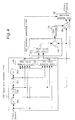
- Fig. 34 shows a block diagram of the prior contour restoration apparatus.
- reference numeral 1 denotes an input terminal for video signals
- 11 and 12 denote delay circuits that delay the signal for a predetermined period of time
- 13, 14, and 15 denote multipliers
- 16 and 18 denote adders
- 17 denotes a gain controller that varies the contour restoration level
- 2 denotes an output terminal.
- Fig. 35 shows the waveforms of signals at points a to i in Fig. 34.
- a video signal input to the input terminal 1 is applied to the delay circuit 11 and the multiplier 13.
- the output signal of the delay circuit 11 is applied to the delay circuit 12, the multiplier 14, and the adder 18.
- the output signal of the delay circuit 12 is applied to the multiplier 15. For example, if a video signal at point a having a waveform (a) of Fig. 35 is input to the input terminal 1, then signals at points b and c output from the delay circuits 11 and 12 have respectively waveforms (b) and (c) of Fig. 34.
- the signal at point h output from the gain controller 17 has a waveform shown in Fig. 35 (h).
- the output signals of the gain controller 17 and the delay circuit 11 are added by the adder 18, which outputs a signal at point i having a waveform (i) of Fig. 35 through the output terminal 2.
- This output signal is the desired signal that has removed a blur of the contour.
- Prior contour restoration apparatus thus improves the sharpness of contours by obtaining a signal having steep slopes in contour parts.
- a contour correcting circuit for emphasizing the contour of a video signal which comprises a plurality of delay circuits, an upper level detector, a lower level detector and a limiter for further processing of the output signals of these two detectors.
- This solution has the disadvantage that signal information at higher and lower levels is lost in the limiting process.
- the contour restoration apparatus of claim 1 provides sufficient effects on contour restoration for gently-sloping contours, and does not add undershoots or overshoots to its restored contour so that contour restoration is achieved without adding unnatural black and white hems to a contour.
- the contour restoration apparatus of claim 3 does not perform contour restoration if the maximum value and the minimum value of the amplitude of the input video signal are attained at unique points in the same direction from a pixel under consideration, so that, in addition to the effects of the apparatus of claim 1, the geometric structure of the original image is not lost.
- the contour restoration apparatus of claim 4 sets the restoration amount at low levels for areas in which contour amplitude is large so that, in addition to the effects of the apparatus of claim 1, distortions that occur in oblique contours are suppressed.
- the contour restoration apparatus of claim 5 outputs restored contour signals with high frequency enhancement for areas in which contour amplitude is large so that, in addition to the effects of the apparatus of claim 1, distortions that occur in oblique contours are suppressed, and effects on contour restoration are also obtained.
- the contour restoration apparatus of claim 6 performs contour restoration after converting the sampling period of the digitized input signal so that, in addition to the effects of the apparatus of claim 1, distortions that occur in oblique contours are suppressed.
- the contour restoration apparatus of claim 7 adjusts the amplitude of a restored contour signal at any given gain, if an undershoot or overshoot is detected by the control signal generator, so that high-slope contours are obtained without adding excessive undershoots or overshoots, and unnaturalness in contours of an image are reduced.
- the contour restoration apparatus of claim 8 invention does not perform contour restoration for areas in which contour amplitude is small so that, in addition to the effects of the apparatus of claim 7 noise and the like are not enhanced.
- a steep slope of a contour is obtained without adding undershoots or overshoots, and contour restoration is achieved without adding unnatural black and white hems to a contour.
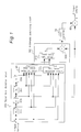
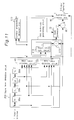
- Fig. 1 shows a block diagram of the contour restoration apparatus according to the first preferred embodiment of the present invention.
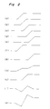
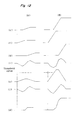
- Fig. 2 shows the waveforms of signals at points a to k indicated in Fig. 1.
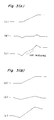
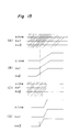
- Fig. 3(A) shows waveforms which represent a contour restoration effect according to the prior art shown in Fig. 34.
- Fig. 3(B) shows waveforms which represent a contour restoration effect according to the first embodiment.
- Fig. 4 shows a block diagram of the contour restoration apparatus of the second preferred embodiment according to the present invention.
- Fig. 5 shows a composition of the non-linear processing circuit shown in Fig. 4.
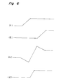
- Fig. 6 shows waveforms of signals at points f to 1 shown in Fig. 6.
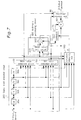
- Fig. 7 shows a block diagram of the contour restoration apparatus according to the third preferred embodiment of the present invention.
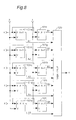
- Fig. 8 shows a block diagram of the location detection circuit shown in Fig. 7.
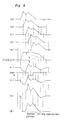
- Fig. 9 shows waveforms of signals at points a to 1 shown in Fig. 7.
- Fig. 10 shows waveforms for showing a manner how a geometric configuration of an original image is lost according to the second preferred embodiment.
- Fig. 11 shows a block diagram of the contour restoration apparatus according to the fourth preferred embodiment of the present invention.
- Fig. 12 shows waveforms of signals at points c to l shown in Fig. 11 when two types of video signals are input, respectively.
- Fig. 13 shows a block diagram of the contour amplitude detector shown in Fig. 12.
- Fig. 14 shows a manner how obtique contours are distorted in the second embodiment.
- Fig. 15 is a microscopic explanation how an image having an oblique contour is distorted in the second embodiment.
- Fig. 16 shows a block diagram of the contour restoration apparatus according to the fifth preferred embodiment of the present invention.
- Fig. 17 shows waveforms of signals at points c, l, q, r, Q and S shown in Fig. 16.
- Fig. 18 shows a block diagram of the contour extractor according to the fifth embodiment.
- Fig. 19 shows a block diagram of the contour restoration apparatus according to the sixth preferred embodiment of the present invention.
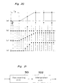
- Fig. 20 shows waveforms of signals according to the sixth embodiment.
- Fig. 21 shows a block diagram of the sampling rate converter of the sixth embodiment.
- Fig. 22 shows a block diagram of the contour restoration apparatus according to the seventh preferred embodiment of the present invention.
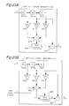
- Figs. 23(A) and 23(B) show block diagrams of the first and second contour restoration circuits according to the seventh embodiment, respectively.
- Fig. 24 shows a block diagram of the combined first and second contour restoration circuits according to the seventh embodiment.
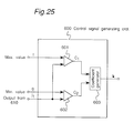
- Fig. 25 shows a block diagram of the control signal generator according to the seventh embodiment.
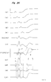
- Fig. 26 shows waveforms of signals at respective points shown in Figs. 23(A) and 23(B) or Fig. 24 according to the seventh embodiment.
- Fig. 27(A) shows characteristic curves of signals restored with various gain values according to the prior art.
- Fig. 27(B) shows a characteristic curve of a signal restored according to the seventh embodiment of the present invention.
- Fig. 28 shows a block diagram of the contour restoration apparatus according to the eighth preferred embodiment of the present invention.
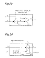
- Fig. 29 shows a block diagram of the contour amplitude detector shown in Fig. 28.
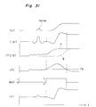
- Fig. 30 shows a block diagram of the switching circuit shown in Fig. 28.
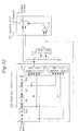
- Fig. 31 shows waveforms of signals at respective points shown in Figs. 28, 29 and 30.
- Fig. 32 shows a block diagram of the contour restoration apparatus according to the ninth preferred embodiment of the present invention.
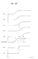
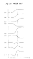
- Fig. 33 shows waveforms of signals at respective points shown in Fig. 32.
- Fig. 34 shows a block diagram of a prior contour restoration apparatus.
- Fig. 35 shows waveforms of signals at respective points shown in Fig. 34.
- Fig. 1 shows a block diagram of the contour restoration apparatus according to the first embodiment of the present invention.
- a reference numeral 1 denotes an input terminal for video signals
- 200 denotes a signal level detection circuit
- 300 denotes an arithmetic processing circuit
- 70 denotes a gain controller
- 80 denotes an adder
- 2 denotes an output terminal.
- the signal level detection circuit 200 comprises four delay circuits 30a, 30b, 30c and 30d which are connected in series to the input terminal 1, a maximum value detection circuit 40 for detecting a maximum value among five signals at points a to e and a minimum value detection circuit 50 for detecting a minimum value among those five signals.
- Each delay circuit delays an input signal for a predetermined delay time set, for example, to the period of one pixel.
- the arithmetic processing circuit comprises a mean value circuit 310 for calculating a mean value from outputs of the maximum and minimum detection circuits 40 and 50 and a subtractor 320 for subtracting the mean value obtained by the mean value circuit 310 from the video signal c delayed by two delay circuits 30a and 30b.
- a video signal applied to the input terminal 1 is applied to the signal level detection circuit 200.
- the input video signal applied to the signal level detection circuit 200 is delayed by the delay circuits 30a, 30b, 30c, and 30d, sequentially, and the input video signal and the output signals of all the delay circuits are input to the maximum value detection circuit 40 and minimum value detection circuit 50, respectively.
- the output signals of the maximum value detector 40, minimum value detector 50, and delay circuit 30b are applied to the arithmetic processing circuit 300, where the output signals of the maximum value detector 40 and minimum value detector 50 are input to the mean value circuit 310, which outputs their mean value.
- the output signal of the mean value circuit 310 is input to one of the input terminals of the subtractor 320, and the output signal of the delay circuit 30b is input to the other input terminal of the subtractor 320.
- the output signal of the subtractor 320 is input to the gain controller 70.
- the output signal gain controlled by the gain controller 70 is provided to one of the input terminals of the adder 80, and the output signal of delay circuit 30b is provided to the other input terminal of the adder 80.
- the added output signal of the adder 80 is output through the output terminal 2 as a video signal having a restored contour.
- a video signal shown in (a) of Fig. 2 is applied to the input terminal 1, then the video signal is input to the signal level detection circuit 200 and delayed one by one by the delay circuits 30a, 30b, 30c and 30d, as shown in (b), (c), (d) and (e) of Fig. 2, respectively.
- the maximum value detection circuit 40 detects the maximum value among signals at points a, b, c, d and e of Fig. 1, and outputs a signal shown in (f) of Fig. 2 at point f.
- the minimum value detection circuit 50 detects the minimum value among signals at points a, b, c, d and e, and outputs the signal shown in (g) of Fig. 2 at point g.
- Signals at points f and g are input to the arithmetic processing circuit 300, in which the mean value circuit 310 obtains a mean value of these signals and outputs a signal shown in (h) of Fig. 2.
- the subtractor 320 subtracts the signal at point h from the signal at point c and outputs a signal shown in (i) of Fig. 2 at point i.
- the amplitude of this output signal is adjusted at any given gain by the gain controller 70, and added to the signal at point c by the adder 80. For example, if the gain of the gain controller 70 is set at 1, then the signal shown in (k) of Fig. 2 is obtained at point k and output through the output terminal 2 as a video signal having a restored contour.
- Fig. 3 shows a comparison of a contour restoration effect of the present embodiment (Fig. 3(B)) on a gently-sloping contour with that of the prior contour restoration apparatus (Fig. 3(A)).
- a contour-restored signal (c) is obtained by adding a restoration signal (b) to an input video signal (a).
- the gain of restoration signals is 1 in both restoration systems. If we compare restored signals (c) of Fig. 3(A) and (c) of Fig. 3(B), we find no effect of contour restoration in the middle of the contour of (c) of Fig. 3(A) compared with (a) of Fig. 3(A), whereas we find clearly a substantial effect in the middle of contour in (c) of Fig. 3(B) compared with (a) of Fig. 3(B).
- an input video signal is restored using a restoration signal obtained by detecting the maximum and minimum amplitude levels of the input video signal in the signal level detection circuit 200 and processing the detected signals and the input video signal in the arithmetic processing circuit 300, so that a sufficient effect of contour restoration is obtained even on a gently-sloping contour.
- Fig. 4 shows a block diagram of the contour restoration apparatus according to the second preferred embodiment of the present invention.
- This embodiment is the same as the first embodiment except an additional nonlinear processing circuit 90 that reads an output signal of the adder 80 and adjusts it with output signals of the maximum value detection circuit 40 and the minimum value detection circuit 50.
- Fig. 5 shows a composition of the non-linear processing circuit 90 employed in the second preferred embodiment.
- This non-linear processing circuit 90 is comprised of first and second comparators 91a and 91b and a selector 92.
- the first comparator 91a compares the output signal k of the adder 80 with the output signal f of the maximum value detection circuit 40 and the second one 91b compares the same with the output signal g of the minimum value detection circuit 50.
- the selector 92 selects either one of three output signals f, k and g in accordance with control signals output from the first and second comparators 91a and 91b.
- the contour restoration apparatus organized as above is described below with reference to Fig. 6.
- the detailed operation is the same as of the first embodiment shown in Fig. 1, until the output signal ((k) of Fig. 5) of the adder 80 is obtained at point k.
- the output signal of the adder 80 is input to the nonlinear processing circuit 90, which also reads signals at points f and g ((f) and (g) of Fig. 6) as control signals. With these control signals the nonlinear processing circuit 90 performs nonlinear processing of the signal at point k.
- a level of the signal at point k is greater than the corresponding level of the signal at point f, then the signal level at point f is output, and if a level of the signal at point k is less than the corresponding level of the signal at point g, then the signal level at point g is output, and the signal level at point k is output in the other case. Then a video signal having a restored contour is obtained at point l as shown in (l) of Fig. 6 and output through the output terminal 2.
- an embodiment according to the second invention provides a sufficient restoration effect on a gently-sloping contour and also does not add undershoots or overshoots so that unnatural black and white hems do not appear on contours.
- the method of restoring contours described above will hereafter be referred to as a contour gradient restoration type.
- Fig. 7 shows a block diagram of a contour restoration apparatus according to the third embodiment of the present invention.
- This embodiment is the same as an embodiment according to the second invention except an additional location detection circuit 100 which detects locations where the maximum and minimum amplitude levels are attained.
- the input video signal and the output signals of delay circuits 30a, 30b, 30c and 30d, maximum value detector 40, and minimum detector 50 are input.
- the output signal of the location detection circuit 100 is input to the gain controller 70.
- the location detection circuit 100 is constructed, for example, as shown in Fig. 8.
- reference numerals 101a, 101b, 101c, 101d, 101e, 101f, 101g, 101h, 101i, and 101j denote comparators
- 120 denotes a logic circuit.
- comparators 101a to 101e compare respectively signals (a) to (e) of Fig. 9 with the output signal (g) of the minimum value detection circuit 50.
- Each comparator outputs a logical value 1, if the compared signals are equal; otherwise another logical value 0 is output.
- the output values of the comparators 101a to 101e are applied to the logic circuit 120 as A1 to A5, respectively.
- comparators 101f to 101j compare signals (a) to (e) with the output signal (f) of the maximum value detection circuit 40, respectively, and output logical results to the logic circuit 120 as B1 to B5, respectively.
- the logic circuit 120 outputs a logical value 0, if one of the eight combinations shown in Table 1 is satisfied; otherwise the logical value 1 is output.
- the input video signal (a), signals (b) to (e) output from the delay circuits 30a, 30b, 30c, 30d, and the output signals (f) and (g) of maximum value detection circuit 40 and minimum value detection circuit (50) are input to the location detection circuit 100.
- the location detection circuit 100 outputs a logical value in according with a combination of input signals with reference Table 1.
- first to fourth combinations indicate the maximum value and the minimum value are detected at point a or b locating before point c as a point under consideration and fifth to eighth combinations indicate the maximum and the minimum values are detected at point d or e locating after point c. If either one of these eight combinations is satisfied, the logic circuit 120 outputs a logical value 0 which indicates a false contour restoration and, accordingly, the contour restoration is cancelled.
- the logical signal output from logic circuit 120 shown in (m) of Fig. 9 is input to the gain controller 70, which sets the gain to 0, if a level of the logical signal is 0. Therefore, the gain controller 70 outputs waveform (j) of Fig. 9, which is then added to waveform (c) of Fig. 9 by the adder 80, which outputs waveform (k) of Fig. 9. As in the second embodiment, waveform (k) of Fig. 9 is processed, based on waveforms (f) and (g) of Fig. 9, in the nonlinear processing circuit 90, which outputs waveform (l) of Fig. 9.
- signal (B) of Fig. 10 is obtained as an output of the maximum value detection circuit 40 and signal (C) of Fig. 10 is obtained as an output of the minimum value detection circuit 50. Therefore, the mean value signal becomes (D) of Fig. 10, and the result obtained by subtracting this mean value signal from the original signal (A) becomes (E) of Fig. 10. This result is then added to the original signal, and signal (F) is obtained.
- This signal (F) is processed by the non-linear processing circuit 90 based on signals (B) and (C) of Fig. 10, and signal (G) is obtained.
- the shallow bottom portion of the original signal (A) is flattened as shown in (G) of Fig. 10 and, therefore, the geometric configuration of the original image is lost.
- the present embodiment does not bring a distortion on the top of a hill-shaped waveform, as shown in (l) of Fig. 9.
- an effect of contour restoration on the falling slope following the hilltop is apparent.
- the third embodiment performs contour restoration without losing the original geometric structure of certain contour images.
- combinations set in the logic circuit 120 are not limited to those shown in Table 1, but a variety of combinations allow the present embodiment to perform more accurate control.
- Fig. 11 shows a block diagram of the contour restoration apparatus according to the fourth preferred embodiment of the present invention.
- This embodiment is the same as the second embodiment except an additional contour amplitude detection circuit 110.
- the contour amplitude detection circuit 110 is provided with the output signals of the maximum value detection circuit 40 and the minimum value detection circuit 50, and the output signal of the contour amplitude detection circuit 110 is input to the gain controller 70.
- the contour amplitude detection circuit 110 is, for example, realized by the circuit of Fig. 13.
- a reference numeral 111 denotes a subtractor
- 112 denotes a coefficient generator.
- output signals (f) and (g) of the maximum value detection circuit 40 and minimum value detection circuit 50 are input to the subtractor 111, which outputs the subtracted signal into the coefficient generator 112.
- the results of the subtractor 111 represent contour amplitude levels.
- the coefficient generator 112 outputs a coefficient Kn, which determines the gain of the gain controller 70, depending on an input contour amplitude level.
- the contour amplitude detection circuit 110 generates a coefficient signal km as a gain control signal and applies the same to the gain controller 70 into which the subtracted signal (i) is input. Therefore, the waveform of the output signal (i) of the subtractor 320 is adjusted to produce waveform (j), which is added to the output signal (c) of the delay circuit 30b by the adder 80 and provided to the nonlinear processing circuit 90.
- the nonlinear processing circuit 90 processes the input signal based on the output signals (f) and (g) of the maximum value detection circuit 40 and the minimum value detection circuit 50 as in the second embodiment and obtains restored contour signals having waveforms (l) of Fig. 12.
- contour signals having different contour amplitude levels shown in (a) of (I) and (II) of Fig. 14, which are the same as waveforms shown in (c) of Fig. 12, are processed by the second embodiment.
- restored contour signals are shown in (B) of (I) and (II) of Fig. 14. Since the amplitude suppressed by the nonlinear processing circuit 90 is large for a contour having a large amplitude, the effects on the improvement of sharpness are large. However, accompanying distortions are also large. The distortions become noticeable if an oblique contour such as shown in (A) of Fig. 15 is restored in images reproduced by raster scanning as in a television system.
- Waveforms corresponding to scanning lines of (A) of Fig. 15 are shown in (B) of Fig. 15. If the image (A) is processed for contour restoration by the second embodiment, then an image shown in (C) of Fig. 15 is obtained, and a stepped distortion is produced in an oblique direction. Waveforms corresponding to scanning lines of (C) of Fig. 15 are shown in (D) of Fig. 15. As is clear from (D) of Fig. 15, the distortion is caused by the fact that the minimum unit of a locational shift for representing an oblique line is a one-pixel period, and the amount of a shift less than a one-pixel period can not be represented. And the greater contour amplitude and effects on contour restoration are, the more noticeable distortions become. If the contour amplitude is small, then distortions are hardly noticeable.
- the present embodiment weakens the effects of contour restoration on a contour having a large amplitude and contrast by setting the gain to a small amount and suppressing distortions produced in an oblique contour.
- the present embodiment performs the same contour restoration as the second embodiment.
- the forth embodiment performs contour restoration without producing distortions for a contour having any amplitude levels in any direction.
- coefficients produced by the coefficient generator 112 are not limited to the two levels of 0.5 and 1.0. These values can be set to different numbers and at many levels depending on contour amplitude.
- Fig. 16 shows a block diagram of the contour restoration apparatus according to the fifth preferred embodiment of the present invention.
- This embodiment is the same as the fourth embodiment except that a contour extraction circuit 120, a gain controller 130, an adder 140, and a mixer 150 are added.
- Signals at points b, c, d in Fig. 16 are applied to the contour extraction circuit 120, whose output is input to the gain controller 130.
- the output signal of the gain controller 130 is provided to one of the input terminals of the adder 140.
- the other input terminal of the adder 140 is provided with the signal at point c, and the added result is provided to one of the input terminals of the mixer 150.
- the other input terminal of the mixer 150 is provided with the output signal of the nonlinear processing circuit 90, and the mixer 150 is controlled by the output signal of the contour amplitude detection circuit 110.
- the output signal of the mixer 150 is applied to the output terminal 2.
- contour restoration apparatus organized as above is described below with reference to Fig. 17.
- contour signals having different amplitude levels shown in (A) and (B) of Fig. 17 are applied to the input terminal 1
- the waveform at point c under consideration is (c) of Fig. 17, and a restored contour signal, whose wave form is shown in (l) of Fig. 17, is output from the nonlinear processing circuit 90 after being treated by a contour gradient restoration type of processing.
- the contour extraction circuit 120 is realized, for example, by the circuit shown in Fig. 18, where 121a, 121b, and 121c denote coefficient multipliers, and 122 denote an adder.
- the contour extraction circuit 120 is a well-known high frequency bandpass filter and extracts a certain contour component. After its amplitude is adjusted by the gain controller 130, the output signal of the contour extraction circuit 120 is added to the original signal (c) of Fig. 17 by the adder 140, which outputs a restored contour signal that is of a high-frequency-enhanced type and has an undershoot and an overshoot, as shown in (r) of Fig. 17.
- the contour amplitude detection circuit 110 is realized by basically the same circuit as in Fig. 13, and a signal shown in (o) of Fig. 17 is obtained as output from the subtractor 111 of Fig. 13.
- the present embodiment suppresses distortions produced in oblique contours and gains contour restoration effects as well by setting a high rate of the restored contour signal of a high-frequency-enhanced type for a contour having large amplitude and contrast. Since the contour restoration of a high-frequency-enhanced type is achieved by linear processing, this type of contour restoration does not produce distortions in oblique contours. On the other hand, the present embodiment performs contour restoration of a contour gradient restoration type for contours having small amplitude.
- an embodiment according to the fifth invention performs contour restoration without producing distortions in oblique contours having any amplitude.
- the mixing rates of the mixer 150 is not limited to three levels but can be set at many levels.
- the composition of the contour extractor 120 is not limited to the described one, but can be any circuit as long as it can realize a high frequency bandpass characteristic.
- Fig. 19 shows a block diagram of the contour restoration apparatus according to the sixth preferred embodiment.
- a reference numeral 500 denotes a sampling rate converter
- 400 denotes a contour restoration section.
- the contour restoration section 400 is basically the same as the second embodiment shown in Fig. 4 except that the delay time of each of the delay circuits 31a, 31b, 31c, and 31d is set to a four-pixel period.
- an input video signal is a sampled sequence of pixels having a sampling period Ts.
- the sampled sequence is input to the sampling rate converter 500, which is realized, for example, by the circuit shown in Fig. 21.
- 501 denotes a zero inserting circuit
- 502 denotes an interpolation circuit connected to the zero inserting circuit 501.
- the sampled sequence (a) of Fig. 20 is applied to the zero inserting circuit 501.
- the zero inserting circuit 501 puts three zero points between two consecutive sampled points at 1/4Ts interval and obtains a new sampled sequence shown in (b) of Fig. 20.
- Sampled sequence (b) is input to the interpolation circuit 502, which is, for example, a weighted adder.
- the interpolation circuit 502 replaces each inserted zero with an interpolated value obtained by adding the levels of the original two consecutive sampled points with weights corresponding to the location of the inserted zero.
- a sampling sequence having sampling period 1/4Ts shown in (c) of Fig. 20 is obtained and input to the contour restoration section 400.
- the contour restoration section 400 performs the same processing as the contour restoration apparatus of the second embodiment and outputs a restored contour signal, ie. a restored sampled sequence, shown in (d) of Fig. 20.
- the sixth embodiment performs contour restoration without producing distortions in oblique contours.
- the conversion rate of sampling period in the sampling rate converter 500 is not limited to 1/4 and can be set to any amount so far as a converted sampling period is less than the original sampling period. Therefore, the delay time of each of the delay circuits 31a, 31b, 31c, and 31d is not limited to 1/4Ts but should be set in accordance with the converted sampling period.
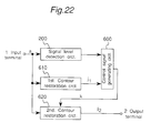
- Fig. 22 shows a block diagram of the contour restoration apparatus according to the seventh preferred embodiment of the present invention.
- a reference numeral 1 denotes an input terminal for video signals
- 200 denotes a signal level detection circuit
- 610 denotes a first contour restoration circuit
- 620 denotes a second contour restoration circuit
- 600 denotes a control signal generator
- 2 denotes an output terminal.
- a video signal applied to the input terminal 1 is applied to the signal level detection circuit 200, first contour restoration circuit 610, and second contour restoration circuit 620, respectively.
- the output signals of the signal level detection circuit 200 and first contour restoration circuit 610 are input to the control signal generator 600.
- the output signal of the control signal generator 600 is input to the control terminal of the second contour restoration circuit 620, and the output signal of the second contour restoration circuit 620 is applied to the output terminal 2.
- Signal level detector 200 is the same as signal level detection circuit 200 according to the first preferred embodiment.
- the first contour restoration circuit 610 and second contour restoration circuit 620 are organized, for example, as shown in Fig. 23(A) and Fig. 23(B), respectively. These are basically the same as prior contour restoration apparatus shown in Fig. 34 except that the output signal of the control signal generator 600 is applied to a gain control terminal of a gain controller 626 of the second contour restoration circuit 620. Alternatively, the first contour restoration circuit 610 and second contour restoration circuit 620 can be combined into the circuit as shown in Fig. 24. In the following description, Fig. 23 is used.
- the control signal generator 600 is realized, for example, by the circuit shown in Fig. 25.
- the output signal f of the maximum value detector 40 of the signal level detection circuit 200 and the output signal j1 of the first contour restoration circuit 610 are input to a comparator 601, where their amplitude levels are compared.
- the output signal g of the minimum value detector 50 of the signal level detection circuit 200 and the output signal j1 of the first contour restoration circuit 610 are input to another comparator 602, where their amplitude levels are compared.
- the output signals c1 and c2 of the comparators 601 and 602 are applied to a coefficient generator 603, whose output signal is applied to the gain control terminal of the gain controller 626 of the second contour restoration circuit 620.
- the input video signal applied to the second contour restoration circuit 620 is processed in the same way up to the adder 625, which outputs the same signal as (h1) of Fig. 26 at point h2.
- the restored contour signal output from the first contour restoration circuit 610 and the maximum and minimum values are input to the control signal generator 600, which detects undershoots and overshoots that were added to the input video signal by the first contour restoration circuit 610 and outputs corresponding predetermined coefficients.
- the input maximum values, ie. the signal at point f, and the output signal of the first contour restoration circuit 610, ie. the signal at point j1 are input to the comparator 601, which compares their amplitude levels. For example, if a level of the output signal of the first contour restoration circuit 610 is greater than the corresponding maximum value, then value 1 is output by the comparator 601; otherwise value 0 is output. Then the output signal of the comparator 601, ie.
- the signal at point c1 becomes (c1) of Fig. 26.
- the input minimum values, ie. the signal at point g, and the output signal of the first contour restoration circuit 610, ie. the signal at point j1 are provided to the comparator 602, which compares their amplitude levels. For example, if a level of the output signal of the first contour restoration circuit 610 is less than the corresponding minimum value, then value 1 is output; otherwise value 0 is output. Then the output signal of the comparator 602, ie. the signal at point c2, becomes (c2) of Fig. 26.
- the output signals of the comparators 601 and 602 are applied to the coefficient generator 603, which, based on them, outputs a coefficient K that determines the gain of the gain controller 626 of the second contour restoration circuit 620.
- the obtained signal is added to the output signal of the delay circuit 621b (the same as the signal at point c) by the adder 627 and output through the output terminal 2 as a video signal having a restored contour shown in (j2) of Fig. 25.
- FIG. 27 shows the contour restoration according to the prior art
- the greater the gain is set the steeper the rising slope of the waveform of the contour-restored signal becomes, and the greater the added amounts of an undershoot and an overshoot become.
- this contour restoration makes black and white hems and an unnatural appearance noticeable in a fine image and in parts where the contour amplitude is small.
- the present embodiment independently adjusts the gain for two different parts of the restoration component, one part that produces an undershoot and an overshoot when added to the input video signal, and the other part that includes a rising part and a falling part.
- the added amount of an undershoot and an overshoot is suppressed while keeping a steep slope at a rising part and a falling part.
- the seventh embodiment adjusts the gain with a different coefficient for an undershoot and overshoot part detected by the control signal generator 600 from the other part so that restored steep contours are obtained without adding excessive undershoots or overshoots, and an unnatural appearance of contours in an image are reduced.
- Fig. 28 shows a block diagram of the contour restoration apparatus according to the eighth preferred embodiment of the present invention.
- This embodiment is the same as the seventh embodiment shown in Fig. 22 except an additional contour amplitude detector 110 that reads the output signals of the signal level detection circuit 200 and an additional switching circuit 640 that reads the input video signal and the output signal of the second contour restoration circuit 620 and is controlled by the output signal of the contour amplitude detection circuit 110.
- contour restoration apparatus organized as above is described below with reference to waveforms of Fig. 31.
- the operation up to second contour restoration circuit 620 is the same as that of an embodiment according to the seventh embodiment.
- the contour amplitude detection circuit 110 is basically the same as the one shown in Fig. 13 and described for the fourth embodiment and comprises subtractor 111 and comparator 113 as shown in Fig. 29.
- the differences between the maximum value, ie. the signal at point f, and the minimum value, ie. the signal at point g, are obtained by the subtractor 111.
- the comparator 113 compares the difference signal, ie. the signal shown in (p) of Fig. 31, with a predetermined threshold value Th and outputs the result. For example, if a level of the difference signal is greater than Th, then 1 is output; otherwise 0 is output. Then the output signal of the comparator 113 becomes the one shown in (kn) of Fig. 31.
- This signal is output from the contour amplitude detection circuit 110 and provided to the control terminal of a switching circuit 640.
- the switching circuit 640 comprises a timing adjuster 641 and a selector 642 as shown in Fig. 30. Based on the control signal at point kn output from the contour amplitude detection circuit 110, the switching circuit 640 selects the output signal at point j2 of the second contour restoration circuit 620, if the control signal is 1; if the control signal is 0, then the input video signal, whose timing is adjusted to that of the signal at point j2 by the timing adjuster 641, is selected.
- the output signal at point p of the subtractor 111 represents the amplitude of a restored contour, and if a level of the amplitude is greater than Th, then the restored contour signal is selected; otherwise the original input video signal is selected. In this way, the signal shown in (t) of Fig. 31 is output to the output terminal 2.
- an embodiment according to the eighth embodiment adjusts the gain with a different coefficient for the undershoot or overshoot part so that a restored steep contour is obtained without adding excessive undershoots or overshoots, and an unnatural appearance of a contour in an image is reduced. Further, the embodiment does not perform contour restoration for the part in which the change of contour amplitude is small so that noise is not enhanced.
- the output signal of the contour amplitude detector 110 can be applied to the coefficient generator 603 of the control signal generator 600, and levels of contour amplitude can be additionally taken into consideration in setting the coefficients.
- the present embodiments according to the seventh and eighth embodiments extracted video signals in the horizontal direction, but the extraction can be made in any direction so far as it is the same as for the detection of the maximum and minimum values.
- video signals can be extracted in the vertical or diagonal direction.
- the coefficients of the coefficient generator 603 are not limited to two values and can be set to many values depending on the amount of amplitude in the shoot part.
- the coefficients for the undershoot part can be set independently of the coefficients for the overshoot part.
- Fig. 32 shows a block diagram of the contour restoration apparatus according to the ninth preferred embodiment of the present invention.
- a reference numeral 1 denotes an input terminal for video signals
- 200 denote a signal level detection circuit
- 310 denotes a mean value circuit
- 700 denotes a switching circuit
- 2 denotes an output terminal.
- the signal level detection circuit 200 has the same composition as the signal level detection circuit 200 of the first embodiment shown in Fig. 1.
- the switching circuit 700 comprises a selector 710, and a comparator 720.
- a video signal applied to the input terminal 1 is input to the signal level detection circuit 200 and delayed by delay circuits 30a, 30b, 30c, and 30d.
- the input video signal and the output signals of the delay circuits 30a, 30b, 30c, and 30d are applied to the maximum value detection circuit 40 and minimum value detection circuit 50.
- the output signals of the maximum value detection circuit 40 and minimum value detection circuit 50 are provided to the mean value circuit 310 and the selector 710 of the switching circuit 700.
- the output signal of the mean value circuit 310 and the output signal of the delay circuit 30b ie. the signal at a point under consideration, are input to the comparator 720 of the switching circuit 700.
- the output signal of the comparator 720 is provided to the control terminal of the selector 710, and the output signal of the selector 710 is output through the output terminal 2 as the output signal of the switching circuit 700.
- a contour restoration apparatus organized as above is described below with reference to waveforms shown in Fig. 33. If, for example, a video signal shown in (a) of Fig. 33 is applied to the input terminal 1, then the signal is delayed by the delay circuits 30a, 30b, 30c, and 30d, and their output signals respectively become (b), (c), (d), and (e) of Fig. 32.
- the input video signal and the output signals of the delay circuits 30a, 30b, 30c, and 30d, ie. signals at points a, b, c, d, and e, are input to the maximum value detection circuit 40 and the minimum value detection circuit 50, where the maximum value (f), and the minimum values (g) input are detected.
- the maximum value and minimum value are input to the mean value circuit 310, which outputs the mean value (h) of Fig. 33.
- the comparator 720 compares each level of the output signal of the mean value circuit 310 with the corresponding level of the output signal of the delay circuit 30b, and the selector 710 selects either one of the corresponding maximum value and minimum value depending on the control signal output from the comparator 720. For example, value 1 is output by the comparator 720, if a level of the output signal of the delay circuit 30b is greater than the corresponding level of the output signal of the mean value circuit 310; otherwise value 0 is output. Then the output control signal of the comparator 720 becomes as shown in (u) of Fig. 33.
- the output signal of the selector 710 becomes a video signal having a restored contour as shown in (v) of Fig. 33 and is output through the output terminal 2 as the output signal of the switching circuit 700.
- the ninth embodiment detects the maximum value, the minimum value, and the mean value of the amplitude of an input video signal and tests whether each amplitude level of a video signal at a point under consideration is greater than the corresponding mean value. If it is, then the corresponding maximum value is selected; otherwise the corresponding minimum value is selected. As a result, a video signal having restored contours are obtained. In this way, the present embodiment obtains a steep contour without adding undershoots or overshoots and performs contour restoration without producing unnatural black and white hems in contour parts.
- the mean value circuit 310 can be modified so that it reads the input video signal and the output signals of the delay circuits 301, 30b, 30c, and 30d instead of the output signals of the maximum value detection circuit 40 and the minimum detection circuit 50 and outputs their mean value.
- video signals at five points in the horizontal direction were extracted in detecting the maximum and minimum values.
- the video signals can be extracted in any predetermined direction, for example, in the vertical or diagonal direction.
- detecting the maximum and minimum values only parts of the extracted signals may be used in detecting the maximum and minimum values; for example, the signal level at every other point can be chosen.
Description
| Combination | A1 | A2 | A3 | A4 | A5 | |
| B1 | B2 | | B4 | B5 | ||
| 1 | 0 | 1 | 0 | 0 | 0 | |
| 0 | 1 | 0 | 0 | 0 | ||
| 2 | 0 | 1 | 0 | 0 | 0 | |
| 1 | 0 | 0 | 0 | 0 | ||
| 3 | 1 | 0 | 0 | 0 | 0 | |
| 0 | 1 | 0 | 0 | 0 | ||
| 4 | 1 | 0 | 0 | 0 | 0 | |
| 1 | 0 | 0 | 0 | 0 | ||
| 5 | 0 | 0 | 0 | 1 | 0 | |
| 0 | 0 | 0 | 1 | 0 | ||
| 6 | 0 | 0 | 0 | 1 | 0 | |
| 0 | 0 | 0 | 0 | 1 | ||
| 7 | 0 | 0 | 0 | 0 | 1 | |
| 0 | 0 | 0 | 1 | 0 | ||
| 8 | 0 | 0 | 0 | 0 | 1 | |
| 0 | 0 | 0 | 0 | 1 |
Claims (10)
- A contour restoration apparatus comprising an input terminal (1) for video signals;characterized bya plurality of delay circuits (30a-30d; 31a-31d) connected in series to said input terminal, each of said plurality of delay circuits having a predetermined delay time for a signal input thereto,a maximum value detection circuit (40) for detecting a maximum value among input video signal and output signals of said plurality of delay circuits,a minimum value detection circuit (50) for detecting a minimum value among signals same as those input to said maximum value detection circuit (40), an output terminal (2) for outputting a contour restored signal,a mean value circuit (310) for calculating a mean value of output signals of said maximum and minimum value detection circuits (40, 50), a subtraction means (320) for subtracting said mean value from an output signal of selected one of said plurality of delay circuits,a gain controller (70) for amplifying the output of said subtraction means (320) with a predetermined gain,an adder (80) for adding the output of said gain controller (70) and said output signal of selected one of said plurality of delay circuits, and providing the contour restored signal to said output terminal (2).
- The contour restoration apparatus according to claim 1, further comprising a nonlinear processing circuit (90) to which the output of said adder (80) and the maximum and minimum values (f, g) output by said maximum and minimum detection circuits (40, 50) are input, said nonlinear processing circuit (90) outputting the maximum value if the output signal of said adder (80) is larger than the maximum value, and outputting the minimum value if the output signal of said adder (80) is smaller than the minimum value, and outputting the output of said adder (80) in the other case.
- The contour restoration apparatus according to claim 2, further comprising a location detection circuit (100) for comparing input video signal and output signals of said plurality of delay circuits (30a-30c) with the maximum value (f) detected by said maximum value detection circuit (40) and comparing input video signal and output signals of said plurality of delay circuits with the minimum value detection circuit (50),
said location detection circuit (100) controlling the gain of the gain controller (70) to zero if the maximum value and the minimum values are detected at the same side when seen from a location of the center signal among input video signal and output signals of said plurality of delay circuits. - The contour restoration apparatus according to claim 2, further comprising a contour amplitude detection circuit (110) for detecting a difference between the maximum value (f) and the minimum value (g) detected by said maximum value detection circuit (40) and minimum value detection circuit (50) and controlling the gain of said gain controller (70) according to said difference detected.
- The contour restoration apparatus according to claim 2, further comprising a contour extraction circuit (120) to which the signal locating centrally among input video signal and output signals of said plurality of delay circuits (30a-30d) and signals locating before and after the center signal are input, said contour extraction circuit comprising multipliers (121a, 121b, 121c) for multiplying each of three signals (b, c, d) input thereto with a predetermined coefficient (K1, K2, K3) and an adder (122) for adding three signals multiplied,wherein kn is a coefficient given by said contour amplitude detection circuit.another gain controller (130) for amplifying the output of said contour extraction circuit (120) with a predetermined gain,another adder (140) for adding the output of said another gain controller (130) and the center signal,a contour amplitude circuit (110) for detecting a difference between the maximum value and the minimum value detected by said maximum value detection circuit (40) and minimum value detection circuit (50) and for outputting a coefficient determined according to the difference detected, and a mixer (150) for mixing the output (I) of said nonlinear processing circuit (90) and the output (r) of said another adder (140) according to an equation
- A contour restoration apparatus according to claim 1,
characterized by said input terminal (1) receiving a string of video signals having been sampled with a first sampling interval,a sampling rate converter (500) for converting said string of video signals to a string of video signals (a) having a second sampling interval which is shorter than said first sampling interval,said plurality of delay circuits (31a-31d) being connected to said sampling rate converter (500) in cascade, each of said plurality of delay circuits having a delay time determined in accordance with said second sampling interval, and said maximum value detection circuit (40) detecting a maximum value among output signal of said sampling rate converter (500) and output signals of said plurality of delay circuits (31a-31d). - A contour restoration apparatus comprising an input terminal (1) for video signals;characterized bya plurality of delay circuits (30a-30d) connected in series to said input terminal (1), each of said plurality of delay circuits having a predetermined delay time for a signal input thereto,a maximum value detection circuit (40) for detecting a maximum value among input video signal (a) and output signals (b, c) of said plurality of delay circuits,a minimum value detection circuit (50) for detecting a minimum value among signals same as those input to said maximum value detection circuit (40), an output terminal (2) for outputting a contour restored signal,a mean value circuit (310) for calculating a mean value (h) of output signals of said maximum and minimum value detection circuits,a comparator (720) for comparing an output signal of selected one of said plurality of delay circuits with said mean value (h) calculated by said mean value circuit (310),a selector (710) for selecting either of said maximum value (f) and minimum value (g) in accordance with the output of said comparator (720) as the contour restored signal to said output terminal (2).
- A contour restoration apparatus comprising an input terminal (1) for video signals and a signal level detection circuit (200) comprising a plurality of delay circuits (30a-30d; 31a-31d) connected in series to said input terminal, each of said plurality of delay circuits having a predetermined delay time for a signal input thereto,characterized bya maximum value detection circuit (40) for detecting a maximum value among input video signal and output signals of said plurality of delay circuits,a minimum value detection circuit (50) for detecting a minimum value among signals same as those input to said maximum value detection circuit (40), an output terminal (2) for outputting a contour restored signal,a first contour restoration circuit (610) being comprised of a plurality of delay circuits (611a-611c) connected to said input terminal (1) in cascade, a plurality of multipliers (612, 613, 614) for multiplying predetermined coefficients (Ka, Kb, Kc) to outputs of said plurality of delay circuits, an adder (615) for adding outputs of said plurality of multipliers, a gain controller (616) for amplifying the output of said adder with a predetermined gain, and another adder (617) for adding the output of selected one of said plurality of delay circuits and the output of said gain controller (616);a second contour restoration circuit (620) being comprised of a plurality of delay circuits (621a-621c) connected to said input terminal (1) in cascade, a plurality of multipliers (622, 623, 624) for multiplying predetermined coefficients (Ka, Kb, Kc) to outputs of said plurality of delay circuits, an adder (625) for adding outputs of said plurality of multipliers, an auto gain controller (626) for amplifying the output of said adder with a gain automatically set,a control signal generation circuit (600) for generating a control signal (k) for said auto gain controller (626) of said second contour restoration circuit (620), to which control signal generation circuit outputs (f, g) of said maximum value and minimum value detection circuits (40, 50) and said first contour restoration circuit (610) are input, said control signal generation circuit (600) controlling the gain of said auto gain controller (626) to a second value smaller than a first value if the output of said first contour restoration circuit (610) is larger than the maximum value or smaller than the minimum value,an adder (627) for adding the output of said auto gain controller (626) and an output of selected one of said plurality of delay circuits (621a-621c) of said second contour restoration circuit (620),and providing the contour restored signal to said output terminal (2).
- The contour restoration apparatus according to claim 8, wherein one set of plural delay circuits (631a-631d), plural multipliers (632-634) and an adder (635) connected to said plural multipliers are used in common for those of said first and second contour restoration circuits (610, 620).
- The contour restoration apparatus according to claim 8, further comprising a contour amplitude detection circuit (110) for detecting a contour amplitude by subtracting the minimum value (g) from the maximum value (f) and for outputting a coefficient in accordance with the contour amplitude detected thereby, and a switching circuit (640) for outputting either of the output of the second contour restoration circuit (620) and the input video signal (a) which is delayed (641) so that the timing thereof coincides with that of the output of the second contour restoration circuit (620) in accordance with the coefficient output from said contour amplitude detection circuit (110).
Applications Claiming Priority (8)
| Application Number | Priority Date | Filing Date | Title |
|---|---|---|---|
| JP4042557A JP2830587B2 (en) | 1992-02-28 | 1992-02-28 | Video signal processing device |
| JP42557/92 | 1992-02-28 | ||
| JP4121669A JP2830609B2 (en) | 1992-05-14 | 1992-05-14 | Contour correction device |
| JP121669/92 | 1992-05-14 | ||
| JP214875/92 | 1992-08-12 | ||
| JP4214875A JP2871323B2 (en) | 1992-08-12 | 1992-08-12 | Video signal processing device |
| JP4216755A JPH0662279A (en) | 1992-08-14 | 1992-08-14 | Video signal processor |
| JP216755/92 | 1992-08-14 |
Publications (3)
| Publication Number | Publication Date |
|---|---|
| EP0558017A2 EP0558017A2 (en) | 1993-09-01 |
| EP0558017A3 EP0558017A3 (en) | 1994-01-12 |
| EP0558017B1 true EP0558017B1 (en) | 1998-06-10 |
Family
ID=27461220
Family Applications (1)
| Application Number | Title | Priority Date | Filing Date |
|---|---|---|---|
| EP93103006A Expired - Lifetime EP0558017B1 (en) | 1992-02-28 | 1993-02-26 | Contour restoration apparatus |
Country Status (4)
| Country | Link |
|---|---|
| US (2) | US5546135A (en) |
| EP (1) | EP0558017B1 (en) |
| KR (1) | KR0143389B1 (en) |
| DE (1) | DE69319000T2 (en) |
Families Citing this family (19)
| Publication number | Priority date | Publication date | Assignee | Title |
|---|---|---|---|---|
| GB2273843B (en) * | 1992-11-30 | 1996-11-27 | Gold Star Co | Apparatus and method for enhancing transient edge of video signal |
| JP3284286B2 (en) * | 1993-12-27 | 2002-05-20 | 三菱電機株式会社 | Waveform response improvement circuit |
| KR0141782B1 (en) * | 1994-09-10 | 1998-06-15 | 구자홍 | Image sharpness apparatus |
| JPH0946554A (en) * | 1995-07-31 | 1997-02-14 | Sony Corp | Image pickup device |
| JPH09214807A (en) * | 1996-01-31 | 1997-08-15 | Canon Inc | Device and method for processing image |
| EP0818932B1 (en) * | 1996-07-09 | 1999-11-10 | STMicroelectronics S.r.l. | Circuit for enhancing chrominance transitions in real-time video reception |
| DE19722358A1 (en) * | 1997-05-28 | 1998-12-03 | Thomson Brandt Gmbh | Process for processing transition areas in an image signal |
| US6088065A (en) * | 1997-09-03 | 2000-07-11 | Victor Company Of Japan, Ltd. | Contour correction apparatus and method |
| KR100370704B1 (en) * | 1998-04-17 | 2003-02-05 | 마쯔시다덴기산교 가부시키가이샤 | False contour correcting apparatus and method |
| KR100343692B1 (en) * | 1998-12-31 | 2002-07-20 | 엘지전자주식회사 | contrast enhancement apparatus of video signal |
| KR100287856B1 (en) * | 1999-02-05 | 2001-04-16 | 구자홍 | Apparatus for chroma signal processing |
| JP3538074B2 (en) * | 1999-08-02 | 2004-06-14 | Necビューテクノロジー株式会社 | Edge enhancement circuit and edge enhancement method |
| JP3743235B2 (en) * | 1999-10-30 | 2006-02-08 | 株式会社富士通ゼネラル | Outline enhancement method and circuit |
| DE10114813C1 (en) | 2001-03-26 | 2002-10-31 | Micronas Munich Gmbh | Method and device for increasing signal transitions in television pictures |
| US7271851B2 (en) * | 2003-01-16 | 2007-09-18 | Samsung Electronics Co., Ltd. | Adaptive color transient improvement |
| JP2005142832A (en) * | 2003-11-06 | 2005-06-02 | Canon Inc | Outline correcting circuit and imaging unit |
| KR100631512B1 (en) * | 2004-08-10 | 2006-10-09 | 엘지전자 주식회사 | Apparatus and method for color transition improvement by using nonlinear laplacian |
| DE102009046616A1 (en) * | 2009-11-11 | 2011-05-19 | Zf Friedrichshafen Ag | inverter |
| JP2013042319A (en) * | 2011-08-15 | 2013-02-28 | Sony Corp | Image processing apparatus, image processing method, and computer program |
Family Cites Families (19)
| Publication number | Priority date | Publication date | Assignee | Title |
|---|---|---|---|---|
| JPS58219872A (en) * | 1982-06-15 | 1983-12-21 | Pioneer Electronic Corp | Circuit for compensating outline |
| JPS6276871A (en) * | 1985-09-30 | 1987-04-08 | Toshiba Corp | Picture quality correction circuit |
| JPS6314577A (en) * | 1986-07-07 | 1988-01-21 | Toshiba Corp | Picture quality improving circuit |
| US4823194A (en) * | 1986-08-01 | 1989-04-18 | Hitachi, Ltd. | Method for processing gray scale images and an apparatus thereof |
| DE3786623T2 (en) * | 1986-09-16 | 1993-12-02 | Victor Company Of Japan | Circuit for processing the video signal. |
| JPH055725Y2 (en) * | 1987-02-06 | 1993-02-15 | ||
| JPS63292777A (en) * | 1987-05-25 | 1988-11-30 | Mitsubishi Electric Corp | Contour correcting device |
| DE68926575T2 (en) * | 1988-02-15 | 1996-09-26 | Victor Company Of Japan | Luminance / color signal isolation circuit |
| IE881234L (en) * | 1988-04-22 | 1989-10-22 | Westinghouse Electric Systems | Image processing system |
| DE68922433T2 (en) * | 1988-05-18 | 1996-01-11 | Hitachi Ltd | Aporture correction circuit. |
| US5231479A (en) * | 1989-10-25 | 1993-07-27 | Hitachi, Ltd. | Luminance/chrominance signal separation circuit having filter circuit using pulse patterns suppressing circuit |
| KR930002906B1 (en) * | 1989-12-23 | 1993-04-15 | 삼성전자 주식회사 | Contour compensation circuit |
| JPH03241976A (en) * | 1990-02-19 | 1991-10-29 | Sony Corp | High frequency portion emphasis circuit |
| US5121209A (en) * | 1990-10-01 | 1992-06-09 | Rca Licensing Corporation | Sharpness control for a television image |
| JP3289892B2 (en) * | 1990-11-13 | 2002-06-10 | パイオニア株式会社 | Signal switching output device |
| JPH04369179A (en) * | 1991-06-18 | 1992-12-21 | Matsushita Electric Ind Co Ltd | Contour correction device |
| US5369446A (en) * | 1992-04-30 | 1994-11-29 | Thomson Consumer Electronics, Inc. | Video signal processor employing edge replacement, preshoots and overshoots for transient enhancement |
| GB2273843B (en) * | 1992-11-30 | 1996-11-27 | Gold Star Co | Apparatus and method for enhancing transient edge of video signal |
| US5515787A (en) * | 1995-01-06 | 1996-05-14 | Middleton; Derrick | Tubular projectile |
-
1993
- 1993-02-25 US US08/022,303 patent/US5546135A/en not_active Expired - Lifetime
- 1993-02-26 DE DE69319000T patent/DE69319000T2/en not_active Expired - Fee Related
- 1993-02-26 EP EP93103006A patent/EP0558017B1/en not_active Expired - Lifetime
- 1993-02-27 KR KR1019930002924A patent/KR0143389B1/en not_active IP Right Cessation
-
1996
- 1996-03-15 US US08/616,283 patent/US5668606A/en not_active Expired - Fee Related
Also Published As
| Publication number | Publication date |
|---|---|
| EP0558017A3 (en) | 1994-01-12 |
| EP0558017A2 (en) | 1993-09-01 |
| DE69319000D1 (en) | 1998-07-16 |
| DE69319000T2 (en) | 1998-11-05 |
| US5668606A (en) | 1997-09-16 |
| KR0143389B1 (en) | 1998-07-15 |
| US5546135A (en) | 1996-08-13 |
| KR930018956A (en) | 1993-09-22 |
Similar Documents
| Publication | Publication Date | Title |
|---|---|---|
| EP0558017B1 (en) | Contour restoration apparatus | |
| US4058836A (en) | Noise reduction in television signals | |
| EP0629083B1 (en) | Interlaced-to-progressive scanning converter having a double-smoothing function and a method therefor | |
| US5481316A (en) | System, apparatus and method for canceling televison ghost signals | |
| US4924305A (en) | Motion detecting circuit for video signal processing using correlation techniques | |
| EP0682841B1 (en) | Noise reduction | |
| EP0314269B1 (en) | Noise eliminating apparatus of video signal | |
| EP0731601B2 (en) | Video signal noise reduction apparatus | |
| GB2102651A (en) | Noise reduction system for color television signal | |
| US6693676B2 (en) | Motion detecting apparatus for detecting motion information of picture within signal | |
| US4504864A (en) | Nonlinear filtering of gray scale images | |
| JP2547686B2 (en) | Video signal processing circuit | |
| US7391476B2 (en) | Method and device for interpolating a pixel of an interline of a field | |
| US5497203A (en) | Motion detection circuit for high definition television based on muse | |
| EP0575995B1 (en) | Noise reduction apparatus | |
| US6259480B1 (en) | Sequential scanning converter | |
| US4907073A (en) | Adaptive device for separating luminance signal and color signal | |
| EP0529761B1 (en) | Method and apparatus for motion aperture correction | |
| US5495299A (en) | Noise reducer | |
| JP2871323B2 (en) | Video signal processing device | |
| JP2580891B2 (en) | Scan line interpolation circuit | |
| KR0185930B1 (en) | Noise eliminating apparatus for establishing critical level in according to signal level | |
| US5161016A (en) | Method of interpolating an image signal using a slope correlation and a circuit thereof | |
| KR920003394B1 (en) | Motion detecting circuit | |
| JP2614475B2 (en) | Scan converter |
Legal Events
| Date | Code | Title | Description |
|---|---|---|---|
| PUAI | Public reference made under article 153(3) epc to a published international application that has entered the european phase |
Free format text: ORIGINAL CODE: 0009012 |
|
| 17P | Request for examination filed |
Effective date: 19930226 |
|
| AK | Designated contracting states |
Kind code of ref document: A2 Designated state(s): DE FR GB NL |
|
| PUAL | Search report despatched |
Free format text: ORIGINAL CODE: 0009013 |
|
| AK | Designated contracting states |
Kind code of ref document: A3 Designated state(s): DE FR GB NL |
|
| 17Q | First examination report despatched |
Effective date: 19960708 |
|
| GRAG | Despatch of communication of intention to grant |
Free format text: ORIGINAL CODE: EPIDOS AGRA |
|
| GRAG | Despatch of communication of intention to grant |
Free format text: ORIGINAL CODE: EPIDOS AGRA |
|
| GRAG | Despatch of communication of intention to grant |
Free format text: ORIGINAL CODE: EPIDOS AGRA |
|
| GRAH | Despatch of communication of intention to grant a patent |
Free format text: ORIGINAL CODE: EPIDOS IGRA |
|
| GRAH | Despatch of communication of intention to grant a patent |
Free format text: ORIGINAL CODE: EPIDOS IGRA |
|
| GRAA | (expected) grant |
Free format text: ORIGINAL CODE: 0009210 |
|
| AK | Designated contracting states |
Kind code of ref document: B1 Designated state(s): DE FR GB NL |
|
| PG25 | Lapsed in a contracting state [announced via postgrant information from national office to epo] |
Ref country code: NL Free format text: LAPSE BECAUSE OF FAILURE TO SUBMIT A TRANSLATION OF THE DESCRIPTION OR TO PAY THE FEE WITHIN THE PRESCRIBED TIME-LIMIT Effective date: 19980610 |
|
| REF | Corresponds to: |
Ref document number: 69319000 Country of ref document: DE Date of ref document: 19980716 |
|
| ET | Fr: translation filed | ||
| NLV1 | Nl: lapsed or annulled due to failure to fulfill the requirements of art. 29p and 29m of the patents act | ||
| PLBE | No opposition filed within time limit |
Free format text: ORIGINAL CODE: 0009261 |
|
| STAA | Information on the status of an ep patent application or granted ep patent |
Free format text: STATUS: NO OPPOSITION FILED WITHIN TIME LIMIT |
|
| 26N | No opposition filed | ||
| PGFP | Annual fee paid to national office [announced via postgrant information from national office to epo] |
Ref country code: DE Payment date: 19991231 Year of fee payment: 8 |
|
| PGFP | Annual fee paid to national office [announced via postgrant information from national office to epo] |
Ref country code: GB Payment date: 20000223 Year of fee payment: 8 |
|
| PGFP | Annual fee paid to national office [announced via postgrant information from national office to epo] |
Ref country code: FR Payment date: 20000224 Year of fee payment: 8 |
|
| PG25 | Lapsed in a contracting state [announced via postgrant information from national office to epo] |
Ref country code: GB Free format text: LAPSE BECAUSE OF NON-PAYMENT OF DUE FEES Effective date: 20010226 |
|
| GBPC | Gb: european patent ceased through non-payment of renewal fee |
Effective date: 20010226 |
|
| PG25 | Lapsed in a contracting state [announced via postgrant information from national office to epo] |
Ref country code: FR Free format text: LAPSE BECAUSE OF NON-PAYMENT OF DUE FEES Effective date: 20011031 |
|
| REG | Reference to a national code |
Ref country code: FR Ref legal event code: ST |
|
| PG25 | Lapsed in a contracting state [announced via postgrant information from national office to epo] |
Ref country code: DE Free format text: LAPSE BECAUSE OF NON-PAYMENT OF DUE FEES Effective date: 20011201 |