EP0557685B1 - A compact lift vehicle with a vertically movable platform - Google Patents
A compact lift vehicle with a vertically movable platform Download PDFInfo
- Publication number
- EP0557685B1 EP0557685B1 EP93100070A EP93100070A EP0557685B1 EP 0557685 B1 EP0557685 B1 EP 0557685B1 EP 93100070 A EP93100070 A EP 93100070A EP 93100070 A EP93100070 A EP 93100070A EP 0557685 B1 EP0557685 B1 EP 0557685B1
- Authority
- EP
- European Patent Office
- Prior art keywords
- vertical post
- lift vehicle
- aerial lift
- post
- platform
- Prior art date
- Legal status (The legal status is an assumption and is not a legal conclusion. Google has not performed a legal analysis and makes no representation as to the accuracy of the status listed.)
- Expired - Lifetime
Links
Images




Classifications
-
- B—PERFORMING OPERATIONS; TRANSPORTING
- B66—HOISTING; LIFTING; HAULING
- B66B—ELEVATORS; ESCALATORS OR MOVING WALKWAYS
- B66B9/00—Kinds or types of lifts in, or associated with, buildings or other structures
- B66B9/16—Mobile or transportable lifts specially adapted to be shifted from one part of a building or other structure to another part or to another building or structure
-
- B—PERFORMING OPERATIONS; TRANSPORTING
- B66—HOISTING; LIFTING; HAULING
- B66F—HOISTING, LIFTING, HAULING OR PUSHING, NOT OTHERWISE PROVIDED FOR, e.g. DEVICES WHICH APPLY A LIFTING OR PUSHING FORCE DIRECTLY TO THE SURFACE OF A LOAD
- B66F11/00—Lifting devices specially adapted for particular uses not otherwise provided for
- B66F11/04—Lifting devices specially adapted for particular uses not otherwise provided for for movable platforms or cabins, e.g. on vehicles, permitting workmen to place themselves in any desired position for carrying out required operations
Definitions
- the present invention relates to an aerial lift vehicle of the type as described in the preamble of claim 1.
- aerial lift vehicle of this type is described in GB-A-2 079 236.
- Aerial lift vehicles of this type are often used for interior finishing or wiring work within buildings.
- Such aerial lift vehicle comprises a running carriage freely capable of traveling, and a vertical post vertically telescopically mounted on the front or rear of the carriage.
- the vertical post includes a boarding platform for supporting an operator thereon and horizontally secured to the post.
- the boarding platform is vertically displaced along the vertical post in conjunction with the telescopic motion of the vertical post caused by the movement of a telescopic cylinder housed in a winch or the vertical post secured to the running carriage.
- aerial lift vehicle conveniently facilitates a variety of aerial works (for example, a work for the attachment of a device to the ceiling indoors) through the travel of the running carriage and the vertical movement of the vertically movable platform at a working site.
- aerial works for example, a work for the attachment of a device to the ceiling indoors
- the conventional aerial lift vehicle although convenient for such works, was relatively large-sized and was not very suitable for the operation in a narrow site or indoors.
- aerial lift vehicle Due to its vertical post detachably mounted on the body and vertically extending upward therefrom, thus configured aerial lift vehicle can be easily disassembled for the convenience of the conveyance and storage by dismounting the vertical post from the body.
- a compact aerial lift vehicle in accordance with a first embodiment of the present invention which comprises a body 10 having pairs of front wheels 18 and rear wheels 19, and a vertical post 20 vertically extending from on the body 10.
- the front wheels 18 consist of casters rotatably coupled to the body 10, while the rear wheels 19 are separately from each other driven by an electric motor as will be described later.
- the vertical post 20 includes a lower post member 21 vertically extending from on the body 10 and removably attached thereto, and an upper post member 25 telescopically combined with the lower post member 21 so as to be vertically displaceable relative to the lower post member 21.
- a plate-like platform 30 for supporting an operator M is mounted on the upper post member 25 at its lower end. In order to support the operator M in an upright manner as shown in Fig. 1B, the platform 30 is made compact with a surface area enough to accommodate the operator M's feet.
- the upper post member 25 has at its upper end a handrail 37 for guarding the operator M standing upright on the platform 30.
- a small-sized basket 39 to be used as a receptacle is attached to the upper front of the upper post member 25.
- the upper post member 25 further includes at its top a manual operating device 35 which is intended to control the travel of the compact aerial lift vehicle as well as the telescopical movement (or vertical displacement) of the vertical post 20.
- the manual operating device 35 having a vertical movement switch and a travel control lever is operated by the operator M standing upright on the platform 30.
- the vertical movement switch allows the upper post member 25 to be raised and lowered, which in turn vertically moves the operator M itself.
- the travel control lever is used to activate the electric motor to control the drive of the rear wheels 19, thereby controlling the travel of the aerial lift vehicle.
- the vertical post 20 further includes a cable 36 leading to the body 10 so as to transmit operation signals from the manual operating device 35 to the body 10.
- the body 10 is covered with a body cover 10a.
- Figs. 3 and 4 illustrate the construction of the body with the body cover 10a removed.
- the body 10 comprises a front frame 11 and a rear frame 12 integrally formed with the front frame 11.
- the front frame 11 has a pair of right and left caster supporting members 11a fixedly secured to the front frame 11 and rotatably supporting the right and left front wheels (casters) 18, respectively.
- the rear frame 12 is provided with a pair of right and left stays 13 for supporting the body cover 10a. As shown in the figures, the rear frame 12 further includes a pair of right and left batteries 52, a charger 51, a controller 53, and a pair of right and left traction motors 54a and 54b.
- the pair of right and left traction motors 54a and 54b are controlled by the controller 53, and driven separately with each other by power supplied from the corresponding batteries 52. Accordingly, the body 10 is allowed to move forward when the right and left traction motors 54a and 54b are forward rotated together, while the body 10 backs when the motors are reversed in unison. When the motors are differently rotated, the body 10 is permitted to turn its travel direction or can be steered. This travel control will be discussed later.
- the controller 53 is composed of a travel controller 53b for controlling the drive of the traction motors 54a and 54b, and a vertical movement controller 53a for the control of the drive of a vertical movement motor which will next be described.
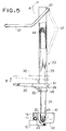
- Fig. 5 depicts the vertical post 20 in enlarged scale.
- the vertical post 20 is removably attached to the front frame 11 by means of a fitting member 22 integrally coupled to the lower end of the lower post 21.
- the fitting member 22 is provided with a reduction gear box 42 having the vertical movement motor 41.
- the lower post member 21 has at its lower portion a drive sprocket 43 which is rotatably attached thereto and driven by the vertical movement motor 41 through the reduction gear box 42.
- the lower post member 21 further includes at its upper portion an idler sprocket 44 rotatably mounted thereto with a looped chain 45 passing between the sprockets 43 and 44.
- the chain 45 vertically extends through a space defined by the lower post member 21 and the upper post member 25 telescopically attached to the lower post member 21 so as to overlap the lower post member 21.
- the chain 45 is formed into a loop by way of a coupling member 46 which is in turn linked with the lower end of the upper post member 25. Due to this structure, the rotation of the drive sprocket 43 by the vertical movement motor 41 through the reduction gear box 42 causes the chain 45 to be driven, which results in a vertical displacement of the upper post member 25.
- the drive of the vertical movement motor 41 is effected by the vertical movement controller 53a in response to the operation of the vertical movement switch on the manual operating device 35.
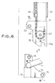
- the fitting member 22 integrally coupled to the lower end of the lower post member 21 is made of a plate material bent into U in section viewed from the lateral side.
- the fitting member 22 has at its lower end an inverted U- shaped receiving recess 22a with a downward facing opening, and has at its upper rear portion a backward projecting locking structure 23.
- the locking structure 23 includes a weld nut 23a joined to the outer side of the fitting member 22 by means of welding, an insertion hole 23b formed coaxially with the weld nut 23a, and a locking bolt 24 adapted to be fit into the insertion hole 23b and to be screwed with the weld nut 23a.
- the body 10 has at its portion receiving the fitting member 22 a support member 14 fixedly secured to the body 10 and spanning between the rear frames 11 and 12.
- the support member 14 presents a forwardly projecting lower portion to which a fitting pipe 15 is rigidly secured with its right and left ends 15a each protruding outward from the support member 14 as shown in Fig. 8.
- the support member 14 also has at its upper portion a hollow pipe 16 firmly attached thereto as shown in Fig. 7.
- a through-hole 16a of the hollow pipe 16 has a diameter enough to receive a threaded portion 24b of the locking bolt 24.
- the fitting pipe 15 is forced into the receiving recess 22a of the fitting member 22 ( in a manner as indicated by an arrow D in Fig. 8) so that the vertical post 20 is placed upright on the support member 14, whereby the fitting member 22 receives the support member 14 so that the insertion hole 23b of the fitting member 22 coincides with the through-hole 16a of the hollow pipe 16 of the support member.
- the threaded portion 24b of the locking bolt 24 is forced into the through-hole 16a via the insertion hole 23b as indicated by an arrow F in Fig. 7, and screwed into the weld nut 23a.
- a head 24a of the locking bolt 24 includes a small hole 24c intended to receive a thin rod, a screwdriver or the like to easily turn the locking bolt 24.
- the fitting member 22 is linked with the support member 14 by means of the locking bolt 24 in the locking structure 23, whereby the vertical post 20 can be easily mounted on the body 10 in an upright condition.
- the vertical post 20 can be easily detached from the body 10.
- the platform 30 has at its foremost end a hook 31 which is to be engaged with a locking bar 26 fastened to the lower front of the upper post member 25, thereby removably attaching the platform 30 to the upper post member 25.
- the platform 30 has on its underside a support arm 32.
- the abutment of the support arm 32 against the rear surface of the upper post member 25 ensures the attachment of the platform 30 to the upper post member. It is to be noted that the platform 30 is undesirably disengaged from the upper post member 25 as shown by a broken line in the figure providing that the platform 30 is pulled up under these circumstances.
- the locking bar 26 is designed to be locked to the upper post member 25 with the aid of a locking bolt, a locking pin or the like. As can be seen from this, when disengaging the platform 30 from the upper post member 25, the platform 30 has only to be pulled up after removing the locking bolt, locking pin or the like.
- the vertical post 20 is detachably mounted on the body 10, while the platform 30 is removably attached to the vertical post 20.
- the aerial lift vehicle of the present invention can be disassembled into three parts as shown in Fig. 9.
- Such disassembly permits the body 10, the vertical post 20 and platform 30 to be separately conveyed and stored, which contributes to the substantial reduction in cost and space required for the conveyance and storage.
- the guard handrail 37 can be turned or jumped upward as indicated by an arrow A in Fig. 5, and folded up into a storage position resting along the front side of the upper post member 25 as indicated by a broken line.
- the guard handrail 37 can be rotated into its storage condition as shown in Fig. 9 when the vertical post 20 is disengaged from the body 30 as described hereinbefore.
- the guard handrail 37 is allowed to be turned or jumped upward in this manner, the operator can get on or off the platform 30 without any difficulty (Refer to Fig. 14).
- Figs. 10 and 11 illustrate a second embodiment of the structure for detachably mounting the vertical post onto the body.
- This aerial lift vehicle comprises a body frame 60 and a lower post member 51 having a gear box 52.
- the lower post member 51 includes a first locking plate 53 horizontally extending and attached to the side of the lower post member 51, and a second locking plate 54 vertically extending and secured thereto.
- the lower post member 51 has at its lower end surface a receiving recess 51a.
- the body frame 60 includes a lock plate 62 horizontally extending and secured thereto, a lock lever 61 rotatably mounted thereon as indicated by an arrow H, and a fitting pipe 65 integral with the body frame 60.
- This structure permits the fitting pipe 65 to be forced into the receiving recess 51a, thereby uprightly placing the lower post member 51 on the fitting pipe 65.
- the first locking plate 53 confronts the lock plate 62
- the second locking plate 54 faces the side of the body frame 60 as can be seen from the figures.
- a lock pin 55 is inserted into through-holes each provided in the first locking plate 53 and lock plate 62, thereby at this point locking the lower post member 51 (or a vertical post) to the body frame 60.
- the lock lever 61 is rotated into a locking arm 54a disposed on the second locking plate 54, thereby also at this point locking the lower post member 51 to the body frame 60.
- Such two-point locking ensures a secure and reliable engagement of the vertical post with the body frame.
- Figs. 12 and 13 illustrate a third embodiment of the aerial lift vehicle of the present invention.
- This aerial lift vehicle also comprises a body 77, and a vertical post 70 detachably mounted on the body 77 and including a lower post member 71 and an upper post member 72.
- the upper post member 72 has at its lower end a support member 73 fixedly attached thereto.
- a platform 75 is coupled to the support member 73 swingably up and down (as indicated by an arrow P in Fig. 12). This structure allows the platform 75 to be swung into a position resting along the upper post member 72 (or a position indicated by a chain line in Fig. 12) when the vertical post 70 is disengaged from the body 77, thereby realizing a compact aerial lift vehicle.
- this aerial lift vehicle has a handrail separated into two parts, that is, right 81 and left 82 handrails.
- the handrails 81 and 82 are each attached through a hinge 83 to the upper post member 72, each independently capable of being turned or jumped upward.
- the operator M conveniently has only to turn or jump one of the handrails 81 and 82 upward, since he or she goes aboard through one side of the vehicle as shown in Fig. 14.
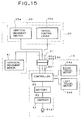
- the vertical post 20 is fitted with the vertical movement motor 41, and the manual operating device 35 having a vertical movement switch 35a and a travel operation lever 35b.
- the body 10 is equipped with the controller 53, battery 52, charger 51, and right and left travel motors 54a and 54b.
- the controller 53 When the controller 53 receives operation signals from the manual operating device 35, it controls the power supply from the battery 52 to the vertical movement motor 41 and the pair of right and left motors 54a and 54b in response to the control signals, thereby controlling the vertical movement of the upper post member 25 and travel of the vehicle.
- the component members are connected by way of signal cables to one another as shown.
- a connector 90 consisting of male 90a and female 90b connectors is used to couple a post-side cable 91 leading to the members placed on the vertical post 20 (the vertical movement motor 41, vertical movement switch 35a and travel operation lever 35b) with a body-side cable 92 leading to the controller 53 disposed on the body 10.
- this connector 90 may be disconnected to sever the cables 91 and 92 at the time of disengagement of the vertical post 20 from the body 10.
- the charger 51 has a plug 51a adapted to be inserted into electric outlets for domestic use.
- domestic electric power can be used for the charge of the battery 52.
Landscapes
- Engineering & Computer Science (AREA)
- Structural Engineering (AREA)
- Life Sciences & Earth Sciences (AREA)
- Geology (AREA)
- Mechanical Engineering (AREA)
- Civil Engineering (AREA)
- Transportation (AREA)
- Automation & Control Theory (AREA)
- Forklifts And Lifting Vehicles (AREA)
Description
- The present invention relates to an aerial lift vehicle of the type as described in the preamble of
claim 1. - An aerial lift vehicle of this type is described in GB-A-2 079 236. Aerial lift vehicles of this type are often used for interior finishing or wiring work within buildings. Such aerial lift vehicle comprises a running carriage freely capable of traveling, and a vertical post vertically telescopically mounted on the front or rear of the carriage. The vertical post includes a boarding platform for supporting an operator thereon and horizontally secured to the post. The boarding platform is vertically displaced along the vertical post in conjunction with the telescopic motion of the vertical post caused by the movement of a telescopic cylinder housed in a winch or the vertical post secured to the running carriage.
- The use of such aerial lift vehicle conveniently facilitates a variety of aerial works (for example, a work for the attachment of a device to the ceiling indoors) through the travel of the running carriage and the vertical movement of the vertically movable platform at a working site.
- The conventional aerial lift vehicle, although convenient for such works, was relatively large-sized and was not very suitable for the operation in a narrow site or indoors.
- Owing to its bulky configuration, it disadvantageously presents its own heavy weight which makes it difficult to carry the aerial lift vehicle itself after and before the operation. In addition, it was sometimes difficult to secure a space enough to accommodate the aerial lift vehicle after the operation. In particular, the vertical post far extending vertically from the running carriage was often a great nuisance at the time of both conveyance and storage.
- It is therefor an object of the present invention to provide an aerial lift vehicle having a compact configuration and suitable for the operation within a narrow site or indoors.
- It is another object of the present invention to provide a compact aerial lift vehicle separable into several parts for the convenience of the conveyance and storage when not used.
- In order to accomplish the above objects, the compact aerial lift vehicle in accordance with
claim 1 has been disclosed. - Due to its vertical post detachably mounted on the body and vertically extending upward therefrom, thus configured aerial lift vehicle can be easily disassembled for the convenience of the conveyance and storage by dismounting the vertical post from the body.
- Embodiments of the present invention are hereinafter described by referring to the figures wherein:
- Figs. 1A and 1B are side elevational views of the compact aerial vehicle constructed in accordance with the present invention, showing its vertical post being shortened and extended, respectively;
- Fig. 2 is a top plan view of the compact aerial vehicle of the present invention;
- Figs. 3 and 4 are perspective views showing the compact aerial lift vehicle according to the present invention with its body cover removed;
- Fig. 5 is a side elevational view of the vertical post of the compact aerial lift vehicle;
- Fig. 6 is an enlarged side elevational view illustrating a coupling section between the vertical post and the body;
- Figs. 7 and 8 are sectional views of the coupling section taken along the arrows VII-VII and VIII-VIII, respectively;
- Fig. 9 is a side elevational view illustrating the compact aerial lift vehicle being disassembled;
- Figs. 10 and 11 are a perspective view and a side elevational view, respectively, showing another constitutional example of the coupling section between the vertical post and the body;
- Fig. 12 is a side elevational view showing the second embodiment of the present invention;
- Figs. 13 and 14 are a perspective view and a side elevational view, respectively, each showing the third embodiment of the present invention; and
- Fig. 15 is a block diagram of a controller incorporated in the aerial lift vehicle constructed in accordance with the present invention.
- Referring now to the drawings, there is illustrated in Figs. 1A, 1B and 2 a compact aerial lift vehicle in accordance with a first embodiment of the present invention which comprises a
body 10 having pairs offront wheels 18 andrear wheels 19, and avertical post 20 vertically extending from on thebody 10. Thefront wheels 18 consist of casters rotatably coupled to thebody 10, while therear wheels 19 are separately from each other driven by an electric motor as will be described later. - The
vertical post 20 includes a lowerpost member 21 vertically extending from on thebody 10 and removably attached thereto, and anupper post member 25 telescopically combined with thelower post member 21 so as to be vertically displaceable relative to thelower post member 21. A plate-like platform 30 for supporting an operator M is mounted on theupper post member 25 at its lower end. In order to support the operator M in an upright manner as shown in Fig. 1B, theplatform 30 is made compact with a surface area enough to accommodate the operator M's feet. Theupper post member 25 has at its upper end ahandrail 37 for guarding the operator M standing upright on theplatform 30. A small-sized basket 39 to be used as a receptacle is attached to the upper front of theupper post member 25. - The upper
post member 25 further includes at its top amanual operating device 35 which is intended to control the travel of the compact aerial lift vehicle as well as the telescopical movement (or vertical displacement) of thevertical post 20. Themanual operating device 35 having a vertical movement switch and a travel control lever is operated by the operator M standing upright on theplatform 30. The vertical movement switch allows the upperpost member 25 to be raised and lowered, which in turn vertically moves the operator M itself. The travel control lever is used to activate the electric motor to control the drive of therear wheels 19, thereby controlling the travel of the aerial lift vehicle. Thevertical post 20 further includes acable 36 leading to thebody 10 so as to transmit operation signals from themanual operating device 35 to thebody 10. - The
body 10 is covered with abody cover 10a. Figs. 3 and 4 illustrate the construction of the body with thebody cover 10a removed. Thebody 10 comprises afront frame 11 and arear frame 12 integrally formed with thefront frame 11. - The
front frame 11 has a pair of right and leftcaster supporting members 11a fixedly secured to thefront frame 11 and rotatably supporting the right and left front wheels (casters) 18, respectively. - The
rear frame 12 is provided with a pair of right andleft stays 13 for supporting thebody cover 10a. As shown in the figures, therear frame 12 further includes a pair of right andleft batteries 52, acharger 51, acontroller 53, and a pair of right andleft traction motors - The pair of right and
left traction motors controller 53, and driven separately with each other by power supplied from thecorresponding batteries 52. Accordingly, thebody 10 is allowed to move forward when the right andleft traction motors body 10 backs when the motors are reversed in unison. When the motors are differently rotated, thebody 10 is permitted to turn its travel direction or can be steered. This travel control will be discussed later. Besides, thecontroller 53 is composed of atravel controller 53b for controlling the drive of thetraction motors vertical movement controller 53a for the control of the drive of a vertical movement motor which will next be described. - Fig. 5 depicts the
vertical post 20 in enlarged scale. Thevertical post 20 is removably attached to thefront frame 11 by means of afitting member 22 integrally coupled to the lower end of thelower post 21. Thefitting member 22 is provided with areduction gear box 42 having thevertical movement motor 41. Thelower post member 21 has at its lower portion adrive sprocket 43 which is rotatably attached thereto and driven by thevertical movement motor 41 through thereduction gear box 42. The lowerpost member 21 further includes at its upper portion an idler sprocket 44 rotatably mounted thereto with a loopedchain 45 passing between thesprockets - The
chain 45 vertically extends through a space defined by the lowerpost member 21 and the upperpost member 25 telescopically attached to thelower post member 21 so as to overlap thelower post member 21. Thechain 45 is formed into a loop by way of acoupling member 46 which is in turn linked with the lower end of theupper post member 25. Due to this structure, the rotation of the drive sprocket 43 by thevertical movement motor 41 through thereduction gear box 42 causes thechain 45 to be driven, which results in a vertical displacement of theupper post member 25. The drive of thevertical movement motor 41 is effected by thevertical movement controller 53a in response to the operation of the vertical movement switch on themanual operating device 35. - The
fitting member 22 integrally coupled to the lower end of thelower post member 21 is made of a plate material bent into U in section viewed from the lateral side. As is apparent from Fig. 6, thefitting member 22 has at its lower end an inverted U-shaped receiving recess 22a with a downward facing opening, and has at its upper rear portion a backward projectinglocking structure 23. As illustrated in Fig. 7, thelocking structure 23 includes aweld nut 23a joined to the outer side of thefitting member 22 by means of welding, aninsertion hole 23b formed coaxially with theweld nut 23a, and alocking bolt 24 adapted to be fit into theinsertion hole 23b and to be screwed with theweld nut 23a. - On the other hand, the
body 10 has at its portion receiving thefitting member 22 asupport member 14 fixedly secured to thebody 10 and spanning between therear frames support member 14 presents a forwardly projecting lower portion to which afitting pipe 15 is rigidly secured with its right and left ends 15a each protruding outward from thesupport member 14 as shown in Fig. 8. Thesupport member 14 also has at its upper portion ahollow pipe 16 firmly attached thereto as shown in Fig. 7. A through-hole 16a of thehollow pipe 16 has a diameter enough to receive a threadedportion 24b of the lockingbolt 24. - Therefore, the
fitting pipe 15 is forced into the receivingrecess 22a of the fitting member 22 ( in a manner as indicated by an arrow D in Fig. 8) so that thevertical post 20 is placed upright on thesupport member 14, whereby thefitting member 22 receives thesupport member 14 so that theinsertion hole 23b of thefitting member 22 coincides with the through-hole 16a of thehollow pipe 16 of the support member. Then, the threadedportion 24b of the lockingbolt 24 is forced into the through-hole 16a via theinsertion hole 23b as indicated by an arrow F in Fig. 7, and screwed into theweld nut 23a. In order to facilitate this screwing, ahead 24a of the lockingbolt 24 includes asmall hole 24c intended to receive a thin rod, a screwdriver or the like to easily turn thelocking bolt 24. - As a result, with the both ends 15a of the
fitting pipe 15 being fitted into the receivingrecess 22a, thefitting member 22 is linked with thesupport member 14 by means of the lockingbolt 24 in the lockingstructure 23, whereby thevertical post 20 can be easily mounted on thebody 10 in an upright condition. On the contrary, by unscrewing the lockingbolt 24, thevertical post 20 can be easily detached from thebody 10. - Referring now to Fig. 5, the
platform 30 has at its foremost end ahook 31 which is to be engaged with a lockingbar 26 fastened to the lower front of theupper post member 25, thereby removably attaching theplatform 30 to theupper post member 25. Theplatform 30 has on its underside asupport arm 32. In addition to the engagement of thehook 31 with the lockingbar 26 as described above, the abutment of thesupport arm 32 against the rear surface of theupper post member 25 ensures the attachment of theplatform 30 to the upper post member. It is to be noted that theplatform 30 is undesirably disengaged from theupper post member 25 as shown by a broken line in the figure providing that theplatform 30 is pulled up under these circumstances. To prevent this occurring, the lockingbar 26 is designed to be locked to theupper post member 25 with the aid of a locking bolt, a locking pin or the like. As can be seen from this, when disengaging theplatform 30 from theupper post member 25, theplatform 30 has only to be pulled up after removing the locking bolt, locking pin or the like. - In this manner, the
vertical post 20 is detachably mounted on thebody 10, while theplatform 30 is removably attached to thevertical post 20. Thus, through the disengagement of thevertical post 20 from thebody 10 and the detachment of theplatform 30 from thevertical post 20, the aerial lift vehicle of the present invention can be disassembled into three parts as shown in Fig. 9. Such disassembly permits thebody 10, thevertical post 20 andplatform 30 to be separately conveyed and stored, which contributes to the substantial reduction in cost and space required for the conveyance and storage. - Incidentally, from a position (or the state shown in Fig. 1B) surrounding and guarding the operator M standing upright on the
platform 30, theguard handrail 37 can be turned or jumped upward as indicated by an arrow A in Fig. 5, and folded up into a storage position resting along the front side of theupper post member 25 as indicated by a broken line. By virtue of this structure, theguard handrail 37 can be rotated into its storage condition as shown in Fig. 9 when thevertical post 20 is disengaged from thebody 30 as described hereinbefore. Moreover, as theguard handrail 37 is allowed to be turned or jumped upward in this manner, the operator can get on or off theplatform 30 without any difficulty (Refer to Fig. 14). - Figs. 10 and 11 illustrate a second embodiment of the structure for detachably mounting the vertical post onto the body.
- This aerial lift vehicle comprises a
body frame 60 and alower post member 51 having agear box 52. Thelower post member 51 includes afirst locking plate 53 horizontally extending and attached to the side of thelower post member 51, and asecond locking plate 54 vertically extending and secured thereto. In addition, thelower post member 51 has at its lower end surface a receivingrecess 51a. On the other hand, thebody frame 60 includes alock plate 62 horizontally extending and secured thereto, alock lever 61 rotatably mounted thereon as indicated by an arrow H, and afitting pipe 65 integral with thebody frame 60. - This structure permits the
fitting pipe 65 to be forced into the receivingrecess 51a, thereby uprightly placing thelower post member 51 on thefitting pipe 65. In this state, thefirst locking plate 53 confronts thelock plate 62, while thesecond locking plate 54 faces the side of thebody frame 60 as can be seen from the figures. Then, alock pin 55 is inserted into through-holes each provided in thefirst locking plate 53 andlock plate 62, thereby at this point locking the lower post member 51 (or a vertical post) to thebody frame 60. At the same time, thelock lever 61 is rotated into alocking arm 54a disposed on thesecond locking plate 54, thereby also at this point locking thelower post member 51 to thebody frame 60. Such two-point locking ensures a secure and reliable engagement of the vertical post with the body frame. - Figs. 12 and 13 illustrate a third embodiment of the aerial lift vehicle of the present invention.
- This aerial lift vehicle also comprises a
body 77, and avertical post 70 detachably mounted on thebody 77 and including alower post member 71 and anupper post member 72. Theupper post member 72 has at its lower end asupport member 73 fixedly attached thereto. Aplatform 75 is coupled to thesupport member 73 swingably up and down (as indicated by an arrow P in Fig. 12). This structure allows theplatform 75 to be swung into a position resting along the upper post member 72 (or a position indicated by a chain line in Fig. 12) when thevertical post 70 is disengaged from thebody 77, thereby realizing a compact aerial lift vehicle. - Also, this aerial lift vehicle has a handrail separated into two parts, that is, right 81 and left 82 handrails. The
handrails hinge 83 to theupper post member 72, each independently capable of being turned or jumped upward. When getting onto theplatform 75, the operator M conveniently has only to turn or jump one of thehandrails - Based on the first embodiment shown in Figs. 1 to 9, by way of example, the configuration of the travel and vertical movement controller incorporated in the aerial lift vehicle according to the present invention will next be described with reference to Fig. 15.
- As discussed hereinbefore, the
vertical post 20 is fitted with thevertical movement motor 41, and themanual operating device 35 having a vertical movement switch 35a and a travel operation lever 35b. On the other hand, thebody 10 is equipped with thecontroller 53,battery 52,charger 51, and right and lefttravel motors - When the
controller 53 receives operation signals from themanual operating device 35, it controls the power supply from thebattery 52 to thevertical movement motor 41 and the pair of right and leftmotors upper post member 25 and travel of the vehicle. To this end, the component members are connected by way of signal cables to one another as shown. It is to be appreciated since thevertical post 20 is detachably mounted on thebody 10 that aconnector 90 consisting of male 90a and female 90b connectors is used to couple apost-side cable 91 leading to the members placed on the vertical post 20 (thevertical movement motor 41, vertical movement switch 35a and travel operation lever 35b) with a body-side cable 92 leading to thecontroller 53 disposed on thebody 10. Thus, thisconnector 90 may be disconnected to sever thecables 91 and 92 at the time of disengagement of thevertical post 20 from thebody 10. - Incidentally, the
charger 51 has aplug 51a adapted to be inserted into electric outlets for domestic use. Thus, domestic electric power can be used for the charge of thebattery 52.
Claims (14)
- An aerial lift vehicle having a vertically movable platform (30,75) comprising:
a body (10,60,77) having wheels (18,19) so as to be capable of travelling;
a vertical post (20,51,70) mounted on said body (10,60,77) and vertically extending upward therefrom in a telescopical manner;
a platform (30,75) attached to the upper portion (25,72) of said vertical post (20,51,70) and vertically movable corresponding to the telescopical movement of said vertical post (20,51,70);
a travel drive means (54a,54b) which drives said wheels (18,19) for the travel of said vehicle;
a telescopical drive means (41) which imparts a telescopical movement to said vertical post (20,51,70); and
a manual operating device (35) attached to the upper portion (25,72) of said vertical post (20,51,70) and for drivingly controlling said travel drive means (54a,54b) and said telescopic drive means (41), said device operable by an operator boarding said platform (30,75),
characterised by
a detachable mounting means
(22,23;51a,65,53,54,55,61,62;90) provided between said vertical post (20,51,70) and said body (10,60,77), said mounting means (22,23;51a,65,53,54,55,61,62;90) being adapted to allow an operator to disassemble said vertical post (20,51,70) from said body (10,60,77) for providing a compact aerial lift vehicle for storage and transport, and to allow an operator to mount said vertical post (20,51,70) in a fixed vertically extending position to said body (10,60,77) for use as an aerial lift vehicle. - An aerial lift vehicle according to claim 1, wherein said vertical post (20,51,70) includes a fixed post member (21,51,71) detachably mounted on said body (10,60,77) and vertically extending upward therefrom, and a vertically movable post member (25,72) mounted vertically slidably with respect to said fixed post member (21,51,71), and wherein said vertically movable post member (25,72) includes said platform (30,75) and said manual operating device (35) attached thereto.
- An aerial lift vehicle according to claim 2, wherein said telescopical drive means (41) includes a drive motor secured to said fixed post member (21,51,71), and a chain mechanism, said chain mechanism having a pair of sprockets (43,44) attached to the upper and lower portions, respectively, of said fixed post member (21,51,71), and having a chain (45) passing between said sprockets (43,44), and wherein said vertically movable post member (25,72) is linked with said chain (45), and said drive motor (41) rotates said sprocket (43), which in turn moves said chain (45), thereby telescopically displacing said vertically movable post member (25,72) along with said chain (45).
- An aerial lift vehicle according to claim 1, wherein the detachable mounting means include a receiving recess (22a,51a) at the lower end of said vertical post (20,51,70) and a fitting section (15,65) at the body (10,60,77) to be fitted into the recess (22a,51a), wherein said vertical post (20,51,70) has at its portion above said lower end a locking mechanism (23,53,54,55,61,62) to be locked with said body (10,60,70) and wherein said vertical post (20,51,70) is placed on said body (10,60,77) in such a manner that said fitting portion (15,65) is fitted into said receiving recess (22a,51a), and then said vertical post (20,51,70) is locked to said body (10,60,77) with the aid of said locking mechanism (23,53,54,55,61,62), thereby detachably mounting said vertical post member (20,51,70) on said body (10,60,77) so as to vertically extend upward therefrom.
- An aerial lift vehicle according to claim 4, wherein said locking mechanism (23,53,54,55,61,62) includes a plurality of locking mechanisms each differently locked so that said vertical post (20,51,70) can be locked to said body (10,60,77) at a plurality of points.
- An aerial lift vehicle according to any one of claims 1 to 5, wherein said platform (30,75) comprises a plate member having a surface area enough to accommodate both feet of an operator standing upright on said platform (30,75).
- An aerial lift vehicle according to any one of claims 1 to 6, wherein said platform (30) is detachably mounted on said vertical post (20).
- An aerial lift vehicle according to any one of claims 1 to 6, wherein said platform (75) is foldable by swinging from a working position projecting horizontally from said vertical post (70) to a storage position resting along said vertical post (70).
- An aerial lift vehicle according to any one of claims 1 to 8, further comprising a guard member (37,81,82) for guarding the operator standing upright on said platform (30,75) and attached to said vertical post (20,51,70) so as to surround said operator.
- An aerial lift vehicle according to claim 9, wherein said guard member (37,81,82) is swingably jumped upward from a working position surrounding the operator boarding said platform (30,75).
- An aerial lift vehicle according to claim 10, wherein said guard member (81,82) is laterally separated into two parts, each independently being swingably jumped upward.
- An aerial lift vehicle according to any one of claims 9 to 11, wherein said guard member (37,81,82) is detachably mounted on said vertical post (20,51,70).
- An aerial lift vehicle according to any one of claims 1 to 12, wherein said vertical post (20,51,70) has at its upper portion a receptacle (39) which is vertically displaceable together with said platform (30,75).
- An aerial lift vehicle according to any one of claims 1 to 13, wherein said travel drive means (54a,54b) includes an electric motor disposed on said body (10,60,77), said telescopic drive means (41) includes an electric motor disposed on said vertical post (20,51,70), and said body (10,60,77) further includes batteries (52) for the supply of the drive power to said electric motors, and a controller (53) for drivingly controlling said motors in response to the operation of said manual operating device (35), said vehicle further comprising:
a first electric cable (91) leading to said manual operating device (35) and said telescopical drive means (41), each arranged on said vertical post (20,51,70);
a second electric cable (92) leading to said travel drive means (54a,54b), said controller (53), and said batteries (52), each arranged on said body (10,60,77); and
a disengageable connector (90) for connecting said first and second electric cables (91,92);
wherein said first and second electric cables (91,92) are separated from each other by decoupling said connector (90) when disengaging said vertical post (20,51,70) from said body (10,60,77).
Applications Claiming Priority (4)
| Application Number | Priority Date | Filing Date | Title |
|---|---|---|---|
| JP18869/92U | 1992-02-28 | ||
| JP1886992U JPH0569079U (en) | 1992-02-28 | 1992-02-28 | Detachable post type aerial work vehicle |
| JP7187992U JPH0627884U (en) | 1992-09-21 | 1992-09-21 | Guard device for aerial work vehicles |
| JP71879/92U | 1992-09-21 |
Publications (3)
| Publication Number | Publication Date |
|---|---|
| EP0557685A2 EP0557685A2 (en) | 1993-09-01 |
| EP0557685A3 EP0557685A3 (en) | 1993-11-10 |
| EP0557685B1 true EP0557685B1 (en) | 1996-05-08 |
Family
ID=26355604
Family Applications (1)
| Application Number | Title | Priority Date | Filing Date |
|---|---|---|---|
| EP93100070A Expired - Lifetime EP0557685B1 (en) | 1992-02-28 | 1993-01-05 | A compact lift vehicle with a vertically movable platform |
Country Status (3)
| Country | Link |
|---|---|
| US (1) | US5273132A (en) |
| EP (1) | EP0557685B1 (en) |
| DE (1) | DE69302499T2 (en) |
Families Citing this family (50)
| Publication number | Priority date | Publication date | Assignee | Title |
|---|---|---|---|---|
| US5992572A (en) * | 1995-10-05 | 1999-11-30 | Crown Equipment Corporation | Personnel carrying vehicle |
| US6241047B1 (en) | 1995-10-05 | 2001-06-05 | Crown Equipment Corporation | Personnel carrying vehicle |
| JPH11513651A (en) * | 1995-10-23 | 1999-11-24 | アップライト,インコーポレイテッド | Personnel lift with movable cage assembly |
| US5803204A (en) * | 1995-10-23 | 1998-09-08 | Upright, Inc. | Personnel lift with clamshell cage assembly |
| EP1012104B1 (en) * | 1996-09-09 | 2005-11-23 | Crown Equipment Corporation | Personnel carrying vehicle |
| USD412866S (en) | 1996-09-13 | 1999-08-17 | Crown Equipment Corporation | Personnel carrying vehicle |
| US6174124B1 (en) * | 1996-10-04 | 2001-01-16 | Crown Equipment Corporation | Load trays for personnel carrying vehicles |
| WO1999011557A1 (en) * | 1997-09-02 | 1999-03-11 | Crown Equipment Corporation | Motor cover for a work assist vehicle |
| EP1009709A1 (en) * | 1997-09-02 | 2000-06-21 | Crown Equipment Corporation | Load trays for personnel carrying vehicles |
| AU746948B2 (en) * | 1997-09-08 | 2002-05-09 | Crown Equipment Corporation | Personnel carrying vehicle |
| USD409349S (en) * | 1997-09-30 | 1999-05-04 | Crown Equipment Corporation | Materials handling and maintenance vehicle |
| USD424777S (en) * | 1998-03-13 | 2000-05-09 | Crown Equipment Corporation | Materials handling and maintenance vehicle |
| FR2788508B1 (en) * | 1999-01-15 | 2001-03-23 | Cimm Cie Ind De Materiels De M | PERSONAL SUPPORT DEVICE FOR HEIGHT LIFTING |
| US6253878B1 (en) * | 1999-08-17 | 2001-07-03 | Dale Wells | Ergonomically adjustable machine operator platform |
| US6471004B2 (en) | 2001-01-31 | 2002-10-29 | Bil-Jax, Inc. | Self locking basket assembly |
| US6401864B1 (en) | 2001-01-31 | 2002-06-11 | Bil-Jax, Inc. | Collapsible stabilizing devices |
| CA2776263A1 (en) * | 2004-04-27 | 2005-11-10 | Jlg Industries, Inc. | Mast lift machine |
| DE502004004451D1 (en) * | 2004-10-13 | 2007-09-06 | Palfinger Ag | work basket |
| US7546902B2 (en) * | 2005-11-07 | 2009-06-16 | Larry Victor Schwertner | Personnel lift apparatus |
| US8292039B2 (en) * | 2006-03-22 | 2012-10-23 | Jlg Industries, Inc. | Mast lift and mast lift system |
| CA2647034C (en) * | 2006-03-22 | 2012-01-10 | Jlg Industries, Inc. | Mast lift and mast lift system |
| USD704914S1 (en) | 2007-03-22 | 2014-05-13 | Jlg Industries, Inc. | Mast lift base |
| US8056677B1 (en) * | 2009-07-23 | 2011-11-15 | Roberts Equipment, Inc. | Lift system with articulably joined subchassis |
| US9675170B2 (en) * | 2009-11-28 | 2017-06-13 | Linak A/S | Telescopic column, preferably for furniture |
| US8308177B2 (en) * | 2010-03-22 | 2012-11-13 | Fravel Gary L | Vehicle access system with powered lift |
| DE102010036409A1 (en) * | 2010-07-15 | 2012-01-19 | Heinz-Gregor Johnen | Mobile personnel lift for use in e.g. field of construction industry, has drive device moving tread relative to undercarriage and comprising drive motor arranged above tread surface in rest position of tread |
| US9505596B2 (en) | 2010-08-17 | 2016-11-29 | Jlg Industries, Inc. | Mast lift with screw drive and gas strut |
| US8789654B2 (en) * | 2010-08-17 | 2014-07-29 | Jlg Industries, Inc. | Mast lift with screw drive and gas strut |
| CN102556897B (en) * | 2011-12-14 | 2014-05-28 | 浙江中力机械有限公司 | Electric order picker |
| US9440830B2 (en) * | 2011-12-14 | 2016-09-13 | Big Lift, Llc | Personnel lift vehicle |
| US9574356B2 (en) * | 2012-08-22 | 2017-02-21 | Cruiser Products, Llc | Vehicle and method for tending to an elevated livestock cage |
| US20150056048A1 (en) * | 2013-03-15 | 2015-02-26 | Tracy Miller | Adjustable and stowable train cargo lift system and method |
| US9187301B2 (en) | 2013-04-22 | 2015-11-17 | Jlg Industries, Inc. | Self-propel accessory |
| USD730614S1 (en) | 2013-11-26 | 2015-05-26 | Big Lift, Llc. | Personnel lift vehicle |
| US20160338486A1 (en) * | 2015-05-19 | 2016-11-24 | Dayna Martin | Height adjustable stand up desk |
| US11046564B2 (en) | 2015-11-09 | 2021-06-29 | Crown Equipment Corporation | Order picker materials handling vehicle with improved downward visibility when driving elevated |
| US10160629B2 (en) | 2017-03-24 | 2018-12-25 | Big Lift, Llc | Electric personnel lift device |
| US10723607B2 (en) | 2017-03-24 | 2020-07-28 | Big Lift, Llc | Electric personnel lift device |
| US10309154B2 (en) | 2017-05-31 | 2019-06-04 | Toyota Motor Engineering & Manufacturing North America, Inc. | Height actuated self-activating safety gate |
| USD891724S1 (en) | 2018-03-23 | 2020-07-28 | Zhejiang E-P Equipment Co., Ltd. | Personnel lift vehicle |
| USD894519S1 (en) | 2018-03-23 | 2020-08-25 | Big Lift, Llc | Personnel lift vehicle |
| CN110713130B (en) * | 2019-10-30 | 2024-10-01 | 天津中车唐车轨道车辆有限公司 | Frock is dismantled to machine that charges |
| EP3838827A1 (en) * | 2019-12-20 | 2021-06-23 | Låglyftar i Sverige AB | Mobile personnel elevator |
| US11787674B2 (en) * | 2020-03-06 | 2023-10-17 | Oshkosh Corporation | Mobility base |
| EP4477614A3 (en) | 2020-06-05 | 2025-03-12 | Crown Equipment Corporation | Operator control system for a materials handling vehicle |
| CN112173529A (en) * | 2020-11-06 | 2021-01-05 | 浙江鼎力机械股份有限公司 | An electric lift type cargo working platform |
| US20230029606A1 (en) * | 2021-07-28 | 2023-02-02 | Brian Paul Froese | Lifting apparatus |
| US20240270547A1 (en) * | 2023-02-15 | 2024-08-15 | Oshkosh Corporation | Lift device |
| USD1070220S1 (en) * | 2023-02-15 | 2025-04-08 | Oshkosh Corporation | Lift |
| USD1070221S1 (en) * | 2023-07-21 | 2025-04-08 | Oshkosh Corporation | Lift |
Family Cites Families (12)
| Publication number | Priority date | Publication date | Assignee | Title |
|---|---|---|---|---|
| US597205A (en) * | 1898-01-11 | Scaffold | ||
| NL97667C (en) * | 1900-01-01 | |||
| US775373A (en) * | 1903-06-12 | 1904-11-22 | Quinn T Moreland | Self-supporting and extension ladder elevator. |
| FR1508972A (en) * | 1966-07-16 | 1968-01-12 | Safety lifting step | |
| US4258825A (en) * | 1978-05-18 | 1981-03-31 | Collins Pat L | Powered manlift cart |
| US4360077A (en) * | 1980-07-02 | 1982-11-23 | Jlg Industries | Aerial lift platform apparatus with control conduit support system |
| US4421209A (en) * | 1982-01-25 | 1983-12-20 | Vermette Machine Company, Inc. | Lift apparatus |
| EP0163430B1 (en) * | 1984-05-01 | 1989-12-20 | Kabushiki Kaisha Hikoma Seisakusho | Elevating apparatus |
| US4987976A (en) * | 1986-06-30 | 1991-01-29 | Vermette Machine Company, Inc. | Telescoping portable lift |
| SE455990B (en) * | 1986-12-29 | 1988-08-29 | Electrolux Ab | PATIENT LIFTING |
| US5052521A (en) * | 1988-05-18 | 1991-10-01 | The Cheney Company | Stairway wheelchair lift |
| US5203425A (en) * | 1991-03-13 | 1993-04-20 | Wehmeyer Donald T | Personnel lift devices |
-
1992
- 1992-12-28 US US07/997,179 patent/US5273132A/en not_active Expired - Fee Related
-
1993
- 1993-01-05 DE DE69302499T patent/DE69302499T2/en not_active Expired - Fee Related
- 1993-01-05 EP EP93100070A patent/EP0557685B1/en not_active Expired - Lifetime
Also Published As
| Publication number | Publication date |
|---|---|
| EP0557685A2 (en) | 1993-09-01 |
| US5273132A (en) | 1993-12-28 |
| EP0557685A3 (en) | 1993-11-10 |
| DE69302499D1 (en) | 1996-06-13 |
| DE69302499T2 (en) | 1996-09-19 |
Similar Documents
| Publication | Publication Date | Title |
|---|---|---|
| US5273132A (en) | Compact aerial lift vehicle with a vertically movable platform | |
| US5020624A (en) | Power drive scooter | |
| US7117967B2 (en) | Wheel chair apparatus and method | |
| US7913978B1 (en) | Portable powered winch | |
| US4199036A (en) | Wheel chair | |
| US5651422A (en) | Universal-fit, quick-connect power drive/steer attachment for wheelchair | |
| US5135063A (en) | Power unit for driving manually-operated wheelchair | |
| US4848504A (en) | Convertible walking/riding golf cart | |
| US5573078A (en) | Steerable, self-powered shopping cart towing apparatus and method for making same | |
| US6145612A (en) | Removable battery case with locking mechanism for a powered wheelchair | |
| US6533067B2 (en) | Scaffold moving device | |
| US5207286A (en) | Steerable wheelchair attachment with powered coupling means | |
| EP2008629A2 (en) | Wheelchair transporter | |
| US5090580A (en) | Trunk-mounted portable crane | |
| US6149372A (en) | Cargo loader | |
| US7296960B2 (en) | Coupling system for attachment of a seat to allow securing and/or lifting thereof | |
| WO2004064698B1 (en) | Ambulance cot loading and unloading device | |
| US4615406A (en) | Golfcart with battery driven drive assist | |
| EP2477932B1 (en) | Articulating work platform and hitch assembly | |
| WO2006091816A2 (en) | Wheelchair transporter | |
| US7374390B2 (en) | Lift mechanism for a seating device | |
| US11021349B2 (en) | Utility vehicle having collapsible game hanger apparatus | |
| EP1747136B1 (en) | Transportation cart primarily for use in an animal barn | |
| JP3120243B2 (en) | Electric motorcycle | |
| CN220767820U (en) | Traffic cone retraction device and engineering vehicle |
Legal Events
| Date | Code | Title | Description |
|---|---|---|---|
| PUAI | Public reference made under article 153(3) epc to a published international application that has entered the european phase |
Free format text: ORIGINAL CODE: 0009012 |
|
| AK | Designated contracting states |
Kind code of ref document: A2 Designated state(s): DE FR GB IT |
|
| PUAL | Search report despatched |
Free format text: ORIGINAL CODE: 0009013 |
|
| RHK1 | Main classification (correction) |
Ipc: B66F 11/04 |
|
| AK | Designated contracting states |
Kind code of ref document: A3 Designated state(s): DE FR GB IT |
|
| 17P | Request for examination filed |
Effective date: 19931228 |
|
| 17Q | First examination report despatched |
Effective date: 19950224 |
|
| GRAH | Despatch of communication of intention to grant a patent |
Free format text: ORIGINAL CODE: EPIDOS IGRA |
|
| GRAA | (expected) grant |
Free format text: ORIGINAL CODE: 0009210 |
|
| ITF | It: translation for a ep patent filed | ||
| AK | Designated contracting states |
Kind code of ref document: B1 Designated state(s): DE FR GB IT |
|
| REF | Corresponds to: |
Ref document number: 69302499 Country of ref document: DE Date of ref document: 19960613 |
|
| ET | Fr: translation filed | ||
| PLBE | No opposition filed within time limit |
Free format text: ORIGINAL CODE: 0009261 |
|
| STAA | Information on the status of an ep patent application or granted ep patent |
Free format text: STATUS: NO OPPOSITION FILED WITHIN TIME LIMIT |
|
| 26N | No opposition filed | ||
| PGFP | Annual fee paid to national office [announced via postgrant information from national office to epo] |
Ref country code: DE Payment date: 19991230 Year of fee payment: 8 |
|
| PGFP | Annual fee paid to national office [announced via postgrant information from national office to epo] |
Ref country code: GB Payment date: 20000105 Year of fee payment: 8 |
|
| PGFP | Annual fee paid to national office [announced via postgrant information from national office to epo] |
Ref country code: FR Payment date: 20000118 Year of fee payment: 8 |
|
| PG25 | Lapsed in a contracting state [announced via postgrant information from national office to epo] |
Ref country code: GB Free format text: LAPSE BECAUSE OF NON-PAYMENT OF DUE FEES Effective date: 20010105 |
|
| GBPC | Gb: european patent ceased through non-payment of renewal fee |
Effective date: 20010105 |
|
| PG25 | Lapsed in a contracting state [announced via postgrant information from national office to epo] |
Ref country code: FR Free format text: LAPSE BECAUSE OF NON-PAYMENT OF DUE FEES Effective date: 20010928 |
|
| PG25 | Lapsed in a contracting state [announced via postgrant information from national office to epo] |
Ref country code: DE Free format text: LAPSE BECAUSE OF NON-PAYMENT OF DUE FEES Effective date: 20011101 |
|
| REG | Reference to a national code |
Ref country code: FR Ref legal event code: ST |
|
| PG25 | Lapsed in a contracting state [announced via postgrant information from national office to epo] |
Ref country code: IT Free format text: LAPSE BECAUSE OF NON-PAYMENT OF DUE FEES Effective date: 20050105 |