EP0557504B1 - Modification of film processor chemistry proportional heating during replenishment - Google Patents
Modification of film processor chemistry proportional heating during replenishment Download PDFInfo
- Publication number
- EP0557504B1 EP0557504B1 EP92919819A EP92919819A EP0557504B1 EP 0557504 B1 EP0557504 B1 EP 0557504B1 EP 92919819 A EP92919819 A EP 92919819A EP 92919819 A EP92919819 A EP 92919819A EP 0557504 B1 EP0557504 B1 EP 0557504B1
- Authority
- EP
- European Patent Office
- Prior art keywords
- temperature
- developer
- chemical
- replenisher
- signalling
- Prior art date
- Legal status (The legal status is an assumption and is not a legal conclusion. Google has not performed a legal analysis and makes no representation as to the accuracy of the status listed.)
- Expired - Lifetime
Links
- 238000010438 heat treatment Methods 0.000 title claims abstract description 32
- 230000004048 modification Effects 0.000 title description 5
- 238000012986 modification Methods 0.000 title description 5
- 239000000126 substance Substances 0.000 claims description 57
- 238000000034 method Methods 0.000 claims description 27
- 230000011664 signaling Effects 0.000 claims description 17
- 238000012545 processing Methods 0.000 claims description 13
- 230000004044 response Effects 0.000 claims description 10
- 230000001105 regulatory effect Effects 0.000 claims 11
- 230000001276 controlling effect Effects 0.000 claims 3
- 238000009529 body temperature measurement Methods 0.000 abstract description 2
- 238000001816 cooling Methods 0.000 description 22
- XLYOFNOQVPJJNP-UHFFFAOYSA-N water Substances O XLYOFNOQVPJJNP-UHFFFAOYSA-N 0.000 description 11
- 230000008859 change Effects 0.000 description 5
- 238000006243 chemical reaction Methods 0.000 description 4
- 238000010586 diagram Methods 0.000 description 4
- 238000004891 communication Methods 0.000 description 3
- 230000000694 effects Effects 0.000 description 3
- 239000012530 fluid Substances 0.000 description 3
- 238000005259 measurement Methods 0.000 description 3
- 230000003134 recirculating effect Effects 0.000 description 3
- 239000000523 sample Substances 0.000 description 3
- 230000004913 activation Effects 0.000 description 2
- 230000002411 adverse Effects 0.000 description 2
- 230000001186 cumulative effect Effects 0.000 description 2
- 238000001514 detection method Methods 0.000 description 2
- 238000011161 development Methods 0.000 description 2
- 238000001035 drying Methods 0.000 description 2
- QSHDDOUJBYECFT-UHFFFAOYSA-N mercury Chemical compound [Hg] QSHDDOUJBYECFT-UHFFFAOYSA-N 0.000 description 2
- 230000000737 periodic effect Effects 0.000 description 2
- 230000008569 process Effects 0.000 description 2
- 101000694320 Drosophila melanogaster RuvB-like helicase 2 Proteins 0.000 description 1
- 235000014676 Phragmites communis Nutrition 0.000 description 1
- 238000012993 chemical processing Methods 0.000 description 1
- 239000000498 cooling water Substances 0.000 description 1
- 238000002059 diagnostic imaging Methods 0.000 description 1
- 230000006870 function Effects 0.000 description 1
- 230000007257 malfunction Effects 0.000 description 1
- 230000007246 mechanism Effects 0.000 description 1
- 238000002156 mixing Methods 0.000 description 1
- 230000000750 progressive effect Effects 0.000 description 1
- 238000011084 recovery Methods 0.000 description 1
- 238000010187 selection method Methods 0.000 description 1
- 238000000926 separation method Methods 0.000 description 1
- 238000006467 substitution reaction Methods 0.000 description 1
- 238000005406 washing Methods 0.000 description 1
Images
Classifications
-
- G—PHYSICS
- G03—PHOTOGRAPHY; CINEMATOGRAPHY; ANALOGOUS TECHNIQUES USING WAVES OTHER THAN OPTICAL WAVES; ELECTROGRAPHY; HOLOGRAPHY
- G03D—APPARATUS FOR PROCESSING EXPOSED PHOTOGRAPHIC MATERIALS; ACCESSORIES THEREFOR
- G03D3/00—Liquid processing apparatus involving immersion; Washing apparatus involving immersion
- G03D3/08—Liquid processing apparatus involving immersion; Washing apparatus involving immersion having progressive mechanical movement of exposed material
- G03D3/13—Liquid processing apparatus involving immersion; Washing apparatus involving immersion having progressive mechanical movement of exposed material for long films or prints in the shape of strips, e.g. fed by roller assembly
- G03D3/132—Liquid processing apparatus involving immersion; Washing apparatus involving immersion having progressive mechanical movement of exposed material for long films or prints in the shape of strips, e.g. fed by roller assembly fed by roller assembly
-
- G—PHYSICS
- G03—PHOTOGRAPHY; CINEMATOGRAPHY; ANALOGOUS TECHNIQUES USING WAVES OTHER THAN OPTICAL WAVES; ELECTROGRAPHY; HOLOGRAPHY
- G03D—APPARATUS FOR PROCESSING EXPOSED PHOTOGRAPHIC MATERIALS; ACCESSORIES THEREFOR
- G03D13/00—Processing apparatus or accessories therefor, not covered by groups G11B3/00 - G11B11/00
- G03D13/006—Temperature control of the developer
-
- G—PHYSICS
- G03—PHOTOGRAPHY; CINEMATOGRAPHY; ANALOGOUS TECHNIQUES USING WAVES OTHER THAN OPTICAL WAVES; ELECTROGRAPHY; HOLOGRAPHY
- G03D—APPARATUS FOR PROCESSING EXPOSED PHOTOGRAPHIC MATERIALS; ACCESSORIES THEREFOR
- G03D13/00—Processing apparatus or accessories therefor, not covered by groups G11B3/00 - G11B11/00
- G03D13/007—Processing control, e.g. test strip, timing devices
Definitions
- the present invention relates to processors of film and similar photosensitive media, in general; and, in particular, to a method for the modification of normal proportional heating cycle operation after introduction of replenisher chemical in a system for controlling the temperature of chemicals in such a processor.
- Photosensitive media processors such as Kodak X-OMAT processors, are useful in applications like the automatic processing of radiographic films for medical imaging purposes.
- the processors automatically transport sheets or rolls of photosensitive film, paper or the like (hereafter "film”) from a feed end of a film transport path, through a sequence of chemical processing tanks in which the film is developed, fixed, and washed, and then through a dryer to a discharge or receiving end.
- the processor typically has a fixed film path length, so final image quality depends on factors including the composition and temperature of the processing chemicals (the processor chemistry"), and the film transport speed (which determines the length of time the film is in contact with the chemistry).
- film transport speed is set at a constant rate and the chemistry is defined according to a preset recommended temperature, e.g. 94°F (34°C), with a specified tolerance range of +/-X°.
- a temperature control system is provided to keep the chemicals within the specified range, and means is provided for automatically replenishing the chemicals as they are used up.
- thermowell located in a developer recirculation path to maintain a desired recommended developer chemical temperature.
- the thermowell has a cartridge heater inserted into one end of a hollow tubular body through which the developer is caused to flow by means of a pump.
- a thermistor protruding into the thermowell flow path serves to monitor the recirculating developer temperature.
- the duty cycle of the heater is varied, based upon data received from the thermistor, in proportion to the proximity of the measured actual temperature to a preestablished developer setpoint temperature. Until the setpoint temperature is reached, a "wait" light or similar annunciator signals the user that an undertemperature condition exists. Once the setpoint temperature is reached, heating and cooling cycles are initiated, as needed, in accordance with detected temperature variations from the setpoint.
- Cooling may be accomplished by operation of a solenoid valve which redirects the developer through a loop in the recirculation path which is in heat exchange relationship with cooler water in the wash tank.
- the fixer whose temperature is less critical, may have its own thermowell recirculation path or may be maintained at a temperature close to the developer temperature by directing it in heat exchange relationship with the developer.
- Processors have been introduced which are settable as to transport speed and chemistry temperature, so that the same processor can be used for multiple processing modes.
- a particular mode is often referred to by a shorthand designation indicative of its associated "drop time,” which corresponds to the time lapse from entry of the leading edge of a film at the feed end of the processor, until exit of the trailing edge of the same film at the discharge end.
- Kodak uses the designations "Kwik” or "K/RA,” “Rapid,” “Standard,” and “Extended” to refer to different userselectable operating modes, each of which has its own characteristic transport speed and developer setpoint temperature.
- replenishment of developer or fixer chemical occurs automatically after a predetermined area of film has passed through the processor, and in response to a low level indicated by a chemical level sensor.
- Replenishment pumps are energized to introduce a slug of fresh developer or fixer from an external source of replenisher chemical. Because the external replenisher source is usually maintained at room temperature and it takes time for the newly introduced slug to mix with the chemical already in the tank, this presents problems for a temperature control system that utilizes a proportional heating cycle. When the unmixed slug of cold replenisher chemical comes into contact with the thermistor, a temperature is measured which does not reflect the temperature of the whole chemical.
- a duty cycle of a heater chosen based on the amount of deviation of such measured temperature from setpoint may provide a heating rate far in excess of that needed considering the temperature of the mass of fluid as a whole. This is especially troublesome where the duty cycle is chosen based on the temperature of a replenisher slug introduced when the chemical as a whole is already at or near setpoint. In such case, the application of too much heat may cause the temperature to overshoot the setpoint target, requiring the consequential activation of one or more, otherwise unnecessary, cooling cycles before the slug is fully mixed and the temperature is again stabilized.
- This object is achieved by the method in accordance with claims 1, 8 and 9.
- the method in accordance with the invention is put into practice in connection with a system for controlling the temperature of chemicals in an automatic film processor includes means for signalling the introduction of replenishment chemical into the processor and means, responsive to such signalling, for modifying the normal operation of a progressive heating cycle to select the heater duty cycle based on the temperature of the overall chemical, and not just the temperature of the replenisher slug.
- An embodiment of the invention is employed with a general purpose radiographic film processor having means for automatically transporting film through developer, fixer, wash and dryer stations according to a selected one of a plurality of available film processing modes, each having an associated characteristic film transport speed and developer setpoint temperature.
- Data corresponding to measured actual developer temperatures occurring at successive times is generated for control and diagnostic purposes under microprocessor supervision, based on measurements taken at periodic time intervals by a temperature sensor in contact with developer flowing in a recirculation path.
- a heater is controlled to maintain the temperature of the developer, with a heater duty cycle chosen based on the magnitude of the deviation of measured developer temperature from setpoint temperature.
- a signal indicative of the recent operation of a developer replenishment pump is used to modify normal heater control after introduction of a slug of replenisher developer, to select a heater duty cycle consistent with the temperature of the developer prior to replenishment.
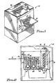
- a temperature control system 10 (FIGS. 3 and 4) suitable for use with a processor 12 (FIGS. 1 and 2) having four user-selectable film modes for the automatic processing of photosensitive film F (FIG. 2), such as for the development of radiographic images for medical diagnostic purposes.
- processor 12 FIGS. 1 and 2
- user-selectable film modes for the automatic processing of photosensitive film F (FIG. 2), such as for the development of radiographic images for medical diagnostic purposes.
- Associated with each mode are default parameters for transport speed; developer and fixer replenishment volumes; developer, fixer and dryer setpoint temperatures; and so forth.
- Such parameters are stored in memory, but can be modified through user input.
- the processor 12 has a feed tray 14 positioned ahead of an entrance opening 15 (FIG. 1).
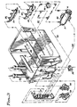
- Patient film F (FIG. 2) entered through entrance opening 15 is transported through processor 12 along a travel path 16 (indicated by arrows in FIG. 2) by a network of conventional motor shaft-driven rollers 17, and eventually into a catch bin 18 at an exit opening 19.
- the path 16 includes travel through a developing station comprising a tank 21 filled with developer chemical; a fixing station comprising a tank 22 filled with fixer chemical; and a wash station comprising a tank 23 filled with wash water or comprising some other appropriate film washing device.
- Processor 12 also includes a drying station 24 comprising oppositely-disposed pluralities of air dispensing tubes 25 or other appropriate film drying mechanism.
- a sensor 26 Positioned proximate opening 15 is a sensor 26, such as a conventional reflective infrared LED sensor array, which provides a signal indicative of film width when film F is presented at the entrance opening 15.
- the film width sensor 26 also provides an indication of the occurrence of passage of the leading edge and trailing edge of film passing point 26 of the processor 12, since the signal from the sensor 26 will change significantly as each leading and trailing edge is encountered.
- a second sensor 27, in the form of a reed switch or the like, may be provided to detect separation of the entrance rollers 28 to signal the beginning of transportation of film F along the path 16.
- the temperature of developer chemical in tank 21 may be controlled by means of a developer recirculation path 30 (shown in dot-dashed lines in FIG. 3) having a pump 31 for drawing developer out of tank 21, passing it through a thermowell 33 incorporating a heater 34 or other suitable heating device, and then passing it back to the tank 21.
- the path 30 also includes means for cooling the developer, such as a solenoid valve 36 which may be operated to redirect the developer through a loop 37 in heat exchange relationship with cooling water in water tank 23.
- the flow of water in tank 23 (see dot-dot-dashed lines in FIG. 3) is under control of a solenoid valve 39.
- a temperature sensor 35 (FIG.
- the sensor 35 may, for example, be a thermocouple provided in the thermowell 33. Developer temperature may be displayed on a panel 38 (FIG. 1) located externally on the processor 12.
- the temperature of fixer chemistry may be controlled in a similar manner by means of a fixer recirculation path 40 (shown in solid lines in FIG. 3) having a pump 41 for drawing fixer out of tank 22, passing it through a thermowell 43 incorporating a heater 44 or other suitable heating device, and then passing it back to the tank 22.
- a temperature sensor 45 such as a thermocouple similar to thermocouple 35, is provided in the tank 22 or recirculation path 40 to monitor the temperature of the fixer. Maintaining the setpoint temperature of the fixer is less critical than maintaining the setpoint temperature of the developer, so no cooling loop is provided.
- the temperature of air in the dryer 24 can be maintained by energizing a blower motor 48 and air heater 49 (FIG. 4) to drive warm air through the tubes 25 (FIG. 2) and across the surface of film F.
- a temperature sensor 52 similar to thermocouple 35 or 45, may be located in the air path to monitor dryer air temperature. It will be appreciated that other ways of controlling processor chemistry and dryer temperatures may be employed.
- Recirculation of developer and fixer takes place when the developer and fixer tanks 21, 22 are full.
- the "full" condition is detected by level sensing sensors 50, 51 (FIG. 4) located in communication with the tanks 21, 22.
- Developer and fixer replenishment occurs automatically if the level falls below a predefined desired level, and after each occurrence of the processing of a preset area of film F.
- Replenishment of developer is accomplished for the developer by energizing a replenishment pump 53 (FIG. 3) connected at its input side to a supply of replenishment developer 54 and at its output side to a filter assembly 55 located in fluid communication with the developer tank 21.
- replenishment is similarly accomplished by energizing of a replenishment pump 56 connected at its input side to a supply of replenishment fixer 57 and at its output side to a filter assembly 58 located in fluid communication with the fixer tank 22.
- the sensors 50, 51 may be of a type having one contact in the form of a probe exposed to the solution and another contact grounded to the case of the heater 34 or 44.
- the probe can be located to monitor solution level in the main tank 21 or 22 or in an associated level-sensing auxiliary reservoir. When the probe becomes immersed in solution, a path is provided to ground and the resistance of the sensor circuit is lowered. The value of the lowered resistance indicates the level of the solution.
- FIG. 4 illustrates a control system usable in implementing an embodiment of the present invention.
- a microprocessor 60 is connected to direct the operation of the processor 12.
- Microprocessor 60 receives input from the user through a mode switch 61 as to what processor mode of operation is desired.
- the system can be configured to enable the user to select among predesignated modes, such as "Kwik” or “K/RA,” “Rapid,” “Standard,” or “Extended” modes, each having predetermined associated film path speed and chemistry temperature parameters prestored in a memory 62.
- the system can also be configured to permit a user to input a desired path speed and temperature directly into memory 62.
- Microprocessor 60 is connected to receive input information from the film width sensor 26, the entrance roller sensor 27, the developer, fixer and dryer temperature sensors 35, 45, 52, the developer and fixer level sensors 50, 51, and from various other sensors and feedback controls.
- the sensors 26, 27 provide the microprocessor 60 with information on the leading and trailing edge occurrences and the width of film F. This can be used together with film speed from a sensor 63 (FIG. 4) which measures the speed of shaft 65 of motor 67 used to drive the rollers 17 (FIG. 2), to give a cumulative processed film area total that guides the control of chemistry replenishment.
- the entrance roller sensor 27 signals when a leading edge of film F has been picked up by the roller path 16. This information can be used together with film speed and known length of the total path 16 to indicate when film F is present along the path 16.
- microprocessor 60 is connected to heater control circuitry 68, 69, cooling control circuitry 70, replenishment control circuitry 72, 73, dryer control circuitry 74, drive motor control circuitry 75 and annunciator control circuitry 77.
- Heater control circuitry 68, 69 is connected to heaters 34, 44, and cooling control circuitry 70 is connected to valves 36, 39 (FIGS. 3 and 4), to control the temperature of the developer and fixer flowing in the recirculation paths 30, 40 (FIG. 3) and, thus, the temperature of the developer and fixer in tanks 21, 22.
- Replenishment control circuitry 72, 73 is connected to valves 53, 56 to control the replenishment of developer and fixer in tanks 21, 22.
- Dryer control circuitry 74 is connected to dryer blower motor 48 and air heater 49 to control the temperature of air in dryer 24.
- Drive motor control circuitry 75 is connected to motor 67 to control the speed of rotation of drive shaft 65 and, thus, of rollers 17. This regulates the speed of travel of film F along film path 16 and, thus, determines the length of time film F spends at each of the stations (i.e., controls development, fixer, wash and dry times).
- Annunciator control circuitry 77 is connected to control the on/off cycles of annunciators in the form of a "Wait" light 78, a "Ready” light 79, and an audible alarm or buzzer 80.
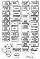
- control system 10 in accordance with the invention is described with reference to FIG. 5 for the control of temperature of chemical in developer tank 21.
- Control of the temperature of fixer in tank 22 can be done similarly, if desired.
- the system When power is applied at start-up, or processor 12 is reset to a different mode (100 in FIG. 5), the system is initialized (101) and system variables, including film speed and setpoint temperature T DS , are set (102).
- pump 53 is deenergized (112) and developer recirculation pump 31 is energized to flow the developer chemical along the recirculation path 30 (114).
- the system 10 is configured so that a replenishment cycle will also take place each time a preset area of film F has been processed.
- Film width sensor 26 at entrance opening 15 is read to determine the presence and width of film F as it passes into the processor 12 (115, 116).
- the cumulative film area is monitored (117) and, when the preset area is reached (118), pump 53 is energized for a preset time t c (119) to deliver a predetermined volume of replenisher chemical into the tank 21.
- Microcomputer 60 uses algorithms and controls to monitor the temperatures of the developer, fixer and dryer air based on signals received from the sensors 35, 45, 52.
- the developer, fixer and dryer thermistors 35, 45, 52 may suitably be connected for shared component processing, to multiplexer circuitry 86 and an analog-to-digital (A/D) converter 87 (FIG. 4).
- the temperature conversions are monitored through a precision resistor 89, which is read at periodic intervals to verify the accuracy of the A/D conversion.
- thermowell 33 While the developer is recirculating (114), thermistor 35 in the thermowell 33 monitors actual developer temperature T DA at time t D (120). The resistance of the thermistor 35 changes inversely with the temperature of the solution. This data is sent to the microprocessor 60, which controls the heating and cooling systems.
- the actual developer temperature T DA is determined by performing an analog-to-digital (A/D) conversion on the resistance of the thermistor 35. This data is then converted to a temperature of °C or o F by means of a software algorithm. The temperature is then compared to the setpoint temperature T DS previously stored in memory 62 to determine if heating or cooling is required (121). The temperature is read periodically at intervals of t, e.g., every 1/2 or 3/4 second.
- Optimum processing quality occurs when the developer temperature is maintained substantially at its setpoint temperature T DS .
- the heating of the developer is controlled by a proportional method.
- Heater 34 is turned on full until the temperature T DA measured by sensor 45 is within 0.5° of the preestablished setpoint T DS .
- Heater 34 then operates on a duty cycle of 75%, until the temperature T DA measured by sensor 45 comes within 0.3° of the setpoint T DS (125, 126).
- Heater 34 then operates on a duty cycle of 50%, until the temperature T DA is within 0.1° of the setpoint T DS (127, 128).
- heater 34 operates on a duty cycle of 25% as the setpoint temperature T DA is approached, until the temperature T DS is reached (127, 129).
- the developer heater shuts off (121, 130).
- a cooling cycle is activated (121, 131). If not already energized, the wash water solenoid 39 is activated to flow water in the tank 23 around the heat exchanger loop 37 (132, 133). The developer cooling solenoid 36 is then energized (135), allowing developer in the recirculating path 30 to circulate through the loop 37. The cooler water in the tank 23 surrounding the heat exchanger 37 acts to cool the developer. The cooler developer then returns to the main recirculation path 30 and back to the tank 23.
- the cooling cycle continues until the developer temperature T DA drops to 0.1° below the setpoint T DS for one reading of the developer thermistor 35 (137).
- the developer cooling solenoid 36 then deenergizes, shutting off the developer supply to the heat exchanger 37 (138). If pump 39 was not already energized when the cooling cycle began, it too is shut off (139, 140).
- the temperature of water flowing in the wash tank 23 should preferably be at a temperature 10°F (6°C) or more below the operating setpoint T DS of the developer temperature.
- the developer heating and cooling systems are responsible for maintaining the developer at the current processing mode temperature setpoint T DS under all operating conditions.
- the developer solution should stabilize at the setpoint temperature T DS within 15-20 minutes after start-up, and within 5 minutes after a mode change.
- the actual temperature T DA and rate R DA of change of actual temperature T DA of the chemical can be monitored to ensure that it is within acceptable limits. Also, the validity of the actual measurements T DA can be verified, and invalid data disregarded for control purposes, in accordance with a procedure as disclosed in US-A-5,245,377.
- Control of developer temperature using proportional heating may be adversely effected by the introduction of a slug of fresh developer at or near room temperature during a replenishment cycle. This is especially so when the developer has already reached a state of equilibrium close to the setpoint temperature T DS . Should the cooler replenisher slug come into contact with the thermistor 35 in thermowell 33 before being fully mixed with the rest of the developer already in the processor 12, a temperature T DA much less than the actual temperature of the whole developer will be recorded (see point 91 in FIG. 7A). When this value is compared with the setpoint T DS at 121, conventional heater duty cycle selection procedures would set a higher duty cycle than necessary to recover from the slight overall cooling effect that will be seen after the slug has become fully mixed.
- the introduction of a slug of replenisher is noted in the control system and taken into account in setting the duty cycle of heater 34.
- the setting of a developer replenishment ("DREP") flag causes the heater duty cycle to be chosen based not only on the current temperature T DA (123, 125, 127, 129), but also on the temperature T DSET of the developer seen before the replenishment cycle occurred.
- a duty cycle of 100% (124) will not be set, unless the prereplenishment temperature T DSET was also less than the setpoint T DS by more than 0.5°. If the deviation from setpoint T DS of the historical temperature T DSET was greater than 0.3°, but not greater than 0.5°, a duty cycle of 75% will be set (125, 153, 126). If the deviation of T DSET was greater than 0.1°, but not greater than 0.3°, a 50% duty cycle will be set (127, 155, 128). And, if the historic value T DSET was within 0.1° of setpoint T DS , a 25% duty cycle is set (127, 155, 129).
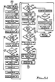
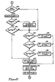
- FIG. 6 shows a modified form of the heater duty cycle selection steps of the process of FIG. 5 wherein, during the period following replenishment and prior to mixing, unless the current measured actual temperature T DA is more than a given amount A° below setpoint T DS (160), the lowest duty cycle will always be set (129).
- FIGS. 7A and 7B show conventional operation; FIG. 7B shows operation with the modification.
- T DA below setpoint T DS occurs in FIG. 7B at point 91 just as in FIG. 7A.
- the selection of a lower duty cycle shows a recovery to a point 93' in FIG. 7B, without overshoot and without the necessity for multiple repetitions of cooling and heating cycles.
- the replenishment and temperature control cycles associated with the fixer chemical in tank 22 can be made similar to those associated with the developer tank 21.
- Tank 22 is both filled and replenished automatically from a connection 57 to a supply of fresh fixer solution.
- fixer is recirculated continuously by a recirculation pump 41 through a thermowell 43 where a thermistor 45 monitors the temperature of the solution.
- the fixer temperature T FA is determined by performing an analog-to-digital (A/D) conversion on the resistance of the thermistor 45 using the same multiplexer circuitry 86, A/D converter 87, and internal A/D converter 88 as for the developer, above. This data is then converted to a temperature in °F or °C by microprocessor 60 by means of a software algorithm. The temperature is then compared to the setpoint T FS stored in memory 62 to determine if heating is required.
- A/D analog-to-digital
- the heater When the temperature T FA is below the setpoint T FS , the heater is turned on. Like the developer, the fixer solution should stabilize at the setpoint temperature T FS within 15-20 minutes after start-up, and within 5 minutes after a mode change.
- the fixer heater 45 is normally operated at full capacity, without proportional regulation of its duty cycle; and the fixer, which operates more effectively at higher temperatures, does not have to be cooled. Nevertheless, there is no reason why proportional heating cannot be used for fixer temperature control, if desired. And, when this is done, regulation following fixer replenishment can proceed as described above for the developer, taking into account misrepresentative temperature readings caused by the cooler slug of fresh fixer.
- air tubes 25 circulate hot air across the film F.
- the tubes 25 are located on both sides of the dryer 24 to dry both sides of the film at the same time.
- the dryer heater 49 heats the air to a setpoint temperature T AS within the range of 90-155°F (38-65.5°C) as set by the user or mode default parameters.
- the actual temperature T AA in the dryer is sensed by a thermistor 52 using the same multiplexer and A/D circuits 86, 87.
- the air temperature T AA is determined by converting the resistance of thermistor 52 into °F or °C. This value is then compared to the setpoint T AS . If the temperature T AR is below the setpoint T AS , the dryer blower 48 and dryer heater 49 are turned on. The blower 48 activates first, with the heater 49 following (this prevents damage to the heater) in response to activation of the vane switch 82 by the blower air. The heater 49 operates at full capacity. When the temperature T AA is above the setpoint T AS , the dryer heater 49 is turned off.
- the processor will enter a standby mode approximately 15 seconds after a film has exited. In the standby mode the water supply is turned off, unless needed for developer cooling; the developer, fixer and dryer temperatures are maintained at their setpoints T DS , T FS and T AS ; and the drive motor 67 is changed to standby operation.
Landscapes
- Physics & Mathematics (AREA)
- General Physics & Mathematics (AREA)
- Photographic Processing Devices Using Wet Methods (AREA)
Abstract
Description
- The present invention relates to processors of film and similar photosensitive media, in general; and, in particular, to a method for the modification of normal proportional heating cycle operation after introduction of replenisher chemical in a system for controlling the temperature of chemicals in such a processor.
- Photosensitive media processors, such as Kodak X-OMAT processors, are useful in applications like the automatic processing of radiographic films for medical imaging purposes. The processors automatically transport sheets or rolls of photosensitive film, paper or the like (hereafter "film") from a feed end of a film transport path, through a sequence of chemical processing tanks in which the film is developed, fixed, and washed, and then through a dryer to a discharge or receiving end. The processor typically has a fixed film path length, so final image quality depends on factors including the composition and temperature of the processing chemicals (the processor chemistry"), and the film transport speed (which determines the length of time the film is in contact with the chemistry).
- In a typical automatic processor of the type to which the invention relates, film transport speed is set at a constant rate and the chemistry is defined according to a preset recommended temperature, e.g. 94°F (34°C), with a specified tolerance range of +/-X°. A temperature control system is provided to keep the chemicals within the specified range, and means is provided for automatically replenishing the chemicals as they are used up.
- Some processors use a thermowell located in a developer recirculation path to maintain a desired recommended developer chemical temperature. The thermowell has a cartridge heater inserted into one end of a hollow tubular body through which the developer is caused to flow by means of a pump. A thermistor protruding into the thermowell flow path serves to monitor the recirculating developer temperature. The duty cycle of the heater is varied, based upon data received from the thermistor, in proportion to the proximity of the measured actual temperature to a preestablished developer setpoint temperature. Until the setpoint temperature is reached, a "wait" light or similar annunciator signals the user that an undertemperature condition exists. Once the setpoint temperature is reached, heating and cooling cycles are initiated, as needed, in accordance with detected temperature variations from the setpoint. Cooling may be accomplished by operation of a solenoid valve which redirects the developer through a loop in the recirculation path which is in heat exchange relationship with cooler water in the wash tank. The fixer, whose temperature is less critical, may have its own thermowell recirculation path or may be maintained at a temperature close to the developer temperature by directing it in heat exchange relationship with the developer.
- Processors have been introduced which are settable as to transport speed and chemistry temperature, so that the same processor can be used for multiple processing modes. A particular mode is often referred to by a shorthand designation indicative of its associated "drop time," which corresponds to the time lapse from entry of the leading edge of a film at the feed end of the processor, until exit of the trailing edge of the same film at the discharge end. Kodak uses the designations "Kwik" or "K/RA," "Rapid," "Standard," and "Extended" to refer to different userselectable operating modes, each of which has its own characteristic transport speed and developer setpoint temperature.
- The operations and functions of automatic film processors are handled under control of electronic circuitry, including a microprocessor connected to various process sensors and subsidiary controls to receive and dispense electronic signals in accordance with predefined software program instructions. Examples of such control circuitry are shown in U.S. Patent No. 4,300,828 and 4,994,837. Earlier European application EP-A-0 551 497 (WO93/03422), entitled Method and Apparatus for Out-of-Rate Error Detection. In a Film Processor", which constitutes prior art in the sense of Article 54(3) EPC, describes a processor temperature control system in which malfunctions in operation of heating and cooling cycles are determined utilizing comparisons of actual and normal rates of change in chemical or dryer air temperature over time. US-A-5,245,377 entitled "Method for Detection of Non-Valid States In a Film Processor Temperature Control System," filed on even date herewith, describes a method for verifying the validity of temperature measurement data based on comparisons of the measured actual temperatures of chemical with predictions as to what valid actual temperature states of the chemicals could be, given the heat gains (or losses) applied in the system during the time interval between measurements.
- In a typical processor of the type to which the invention relates, replenishment of developer or fixer chemical occurs automatically after a predetermined area of film has passed through the processor, and in response to a low level indicated by a chemical level sensor. Replenishment pumps are energized to introduce a slug of fresh developer or fixer from an external source of replenisher chemical. Because the external replenisher source is usually maintained at room temperature and it takes time for the newly introduced slug to mix with the chemical already in the tank, this presents problems for a temperature control system that utilizes a proportional heating cycle. When the unmixed slug of cold replenisher chemical comes into contact with the thermistor, a temperature is measured which does not reflect the temperature of the whole chemical. A duty cycle of a heater chosen based on the amount of deviation of such measured temperature from setpoint may provide a heating rate far in excess of that needed considering the temperature of the mass of fluid as a whole. This is especially troublesome where the duty cycle is chosen based on the temperature of a replenisher slug introduced when the chemical as a whole is already at or near setpoint. In such case, the application of too much heat may cause the temperature to overshoot the setpoint target, requiring the consequential activation of one or more, otherwise unnecessary, cooling cycles before the slug is fully mixed and the temperature is again stabilized.
- It is an object of the present invention to provide a method for modifying the normal operation of a proportional heating cycle after introduction of replenishment chemical in a system for controlling the temperature of chemicals in an automatic film processor. This object is achieved by the method in accordance with
claims - An embodiment of the invention, described in greater detail below, is employed with a general purpose radiographic film processor having means for automatically transporting film through developer, fixer, wash and dryer stations according to a selected one of a plurality of available film processing modes, each having an associated characteristic film transport speed and developer setpoint temperature. Data corresponding to measured actual developer temperatures occurring at successive times is generated for control and diagnostic purposes under microprocessor supervision, based on measurements taken at periodic time intervals by a temperature sensor in contact with developer flowing in a recirculation path. A heater is controlled to maintain the temperature of the developer, with a heater duty cycle chosen based on the magnitude of the deviation of measured developer temperature from setpoint temperature. A signal indicative of the recent operation of a developer replenishment pump is used to modify normal heater control after introduction of a slug of replenisher developer, to select a heater duty cycle consistent with the temperature of the developer prior to replenishment.
- Embodiments of the invention have been chosen for purposes of illustration and description and are shown in the accompanying drawings, wherein:
- FIG. 1 is a perspective view of a processor in which a temperature control system incorporating the present invention can be employed;
- FIG. 2 is a schematic representation of relevant elements of the processor of FIG. 1;
- FIG. 3 is a schematic diagram showing the developer and fixer recirculation paths;
- FIG. 4 is a block diagram of the control system employed in the processor;
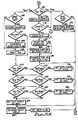
- FIG. 5 is a flow diagram of the operation of the system of FIG. 4;
- FIG. 6 is a modified form of a portion of the flow diagram of FIG. 5; and
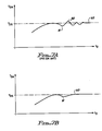
- FIGS. 7A and 7B are graphical representations of typical time variations of chemical temperature over time helpful in understanding the utility of the invention.
- Throughout the drawings, like elements are referred to by like numerals.
- The principles of the invention are illustrated, by way of example, embodied in the form of a temperature control system 10 (FIGS. 3 and 4) suitable for use with a processor 12 (FIGS. 1 and 2) having four user-selectable film modes for the automatic processing of photosensitive film F (FIG. 2), such as for the development of radiographic images for medical diagnostic purposes. Associated with each mode are default parameters for transport speed; developer and fixer replenishment volumes; developer, fixer and dryer setpoint temperatures; and so forth. Such parameters are stored in memory, but can be modified through user input.
- The
processor 12 has afeed tray 14 positioned ahead of an entrance opening 15 (FIG. 1). Patient film F (FIG. 2) entered throughentrance opening 15 is transported throughprocessor 12 along a travel path 16 (indicated by arrows in FIG. 2) by a network of conventional motor shaft-driven rollers 17, and eventually into acatch bin 18 at anexit opening 19. The path 16 includes travel through a developing station comprising atank 21 filled with developer chemical; a fixing station comprising atank 22 filled with fixer chemical; and a wash station comprising atank 23 filled with wash water or comprising some other appropriate film washing device.Processor 12 also includes adrying station 24 comprising oppositely-disposed pluralities ofair dispensing tubes 25 or other appropriate film drying mechanism. - Positioned
proximate opening 15 is asensor 26, such as a conventional reflective infrared LED sensor array, which provides a signal indicative of film width when film F is presented at theentrance opening 15. Thefilm width sensor 26 also provides an indication of the occurrence of passage of the leading edge and trailing edge offilm passing point 26 of theprocessor 12, since the signal from thesensor 26 will change significantly as each leading and trailing edge is encountered. Asecond sensor 27, in the form of a reed switch or the like, may be provided to detect separation of theentrance rollers 28 to signal the beginning of transportation of film F along the path 16. - The temperature of developer chemical in
tank 21 may be controlled by means of a developer recirculation path 30 (shown in dot-dashed lines in FIG. 3) having apump 31 for drawing developer out oftank 21, passing it through athermowell 33 incorporating aheater 34 or other suitable heating device, and then passing it back to thetank 21. Thepath 30 also includes means for cooling the developer, such as asolenoid valve 36 which may be operated to redirect the developer through a loop 37 in heat exchange relationship with cooling water inwater tank 23. The flow of water in tank 23 (see dot-dot-dashed lines in FIG. 3) is under control of asolenoid valve 39. A temperature sensor 35 (FIG. 4) is provided in thetank 21 orrecirculation path 30 to monitor the temperature of the developer. Thesensor 35 may, for example, be a thermocouple provided in thethermowell 33. Developer temperature may be displayed on a panel 38 (FIG. 1) located externally on theprocessor 12. - The temperature of fixer chemistry may be controlled in a similar manner by means of a fixer recirculation path 40 (shown in solid lines in FIG. 3) having a
pump 41 for drawing fixer out oftank 22, passing it through athermowell 43 incorporating aheater 44 or other suitable heating device, and then passing it back to thetank 22. Atemperature sensor 45, such as a thermocouple similar tothermocouple 35, is provided in thetank 22 orrecirculation path 40 to monitor the temperature of the fixer. Maintaining the setpoint temperature of the fixer is less critical than maintaining the setpoint temperature of the developer, so no cooling loop is provided. - The temperature of air in the
dryer 24 can be maintained by energizing a blower motor 48 and air heater 49 (FIG. 4) to drive warm air through the tubes 25 (FIG. 2) and across the surface of film F.A temperature sensor 52, similar tothermocouple - Recirculation of developer and fixer takes place when the developer and
fixer tanks level sensing sensors 50, 51 (FIG. 4) located in communication with thetanks filter assembly 55 located in fluid communication with thedeveloper tank 21. For the fixer, replenishment is similarly accomplished by energizing of areplenishment pump 56 connected at its input side to a supply ofreplenishment fixer 57 and at its output side to a filter assembly 58 located in fluid communication with thefixer tank 22. - The
sensors heater main tank - FIG. 4 illustrates a control system usable in implementing an embodiment of the present invention. As shown, a
microprocessor 60 is connected to direct the operation of theprocessor 12.Microprocessor 60 receives input from the user through amode switch 61 as to what processor mode of operation is desired. The system can be configured to enable the user to select among predesignated modes, such as "Kwik" or "K/RA," "Rapid," "Standard," or "Extended" modes, each having predetermined associated film path speed and chemistry temperature parameters prestored in amemory 62. The system can also be configured to permit a user to input a desired path speed and temperature directly intomemory 62. -
Microprocessor 60 is connected to receive input information from thefilm width sensor 26, theentrance roller sensor 27, the developer, fixer anddryer temperature sensors fixer level sensors sensors microprocessor 60 with information on the leading and trailing edge occurrences and the width of film F. This can be used together with film speed from a sensor 63 (FIG. 4) which measures the speed of shaft 65 ofmotor 67 used to drive the rollers 17 (FIG. 2), to give a cumulative processed film area total that guides the control of chemistry replenishment. Theentrance roller sensor 27 signals when a leading edge of film F has been picked up by the roller path 16. This information can be used together with film speed and known length of the total path 16 to indicate when film F is present along the path 16. - As shown in FIG. 4,
microprocessor 60 is connected toheater control circuitry control circuitry 70,replenishment control circuitry dryer control circuitry 74, drivemotor control circuitry 75 and annunciator control circuitry 77.Heater control circuitry heaters cooling control circuitry 70 is connected tovalves 36, 39 (FIGS. 3 and 4), to control the temperature of the developer and fixer flowing in therecirculation paths 30, 40 (FIG. 3) and, thus, the temperature of the developer and fixer intanks Replenishment control circuitry valves tanks Dryer control circuitry 74 is connected to dryer blower motor 48 andair heater 49 to control the temperature of air indryer 24. Drivemotor control circuitry 75 is connected tomotor 67 to control the speed of rotation of drive shaft 65 and, thus, of rollers 17. This regulates the speed of travel of film F along film path 16 and, thus, determines the length of time film F spends at each of the stations (i.e., controls development, fixer, wash and dry times). Annunciator control circuitry 77 is connected to control the on/off cycles of annunciators in the form of a "Wait" light 78, a "Ready" light 79, and an audible alarm orbuzzer 80. - The operation of the control system 10 in accordance with the invention is described with reference to FIG. 5 for the control of temperature of chemical in
developer tank 21. Control of the temperature of fixer intank 22 can be done similarly, if desired. - When power is applied at start-up, or
processor 12 is reset to a different mode (100 in FIG. 5), the system is initialized (101) and system variables, including film speed and setpoint temperature TDS, are set (102). Thewash water solenoid 39 is energized, allowing water to flow into thetank 23; and the developer solution level is checked by reading sensor 50 (103). If the level is low, a developer replenishment cycle is activated, as necessary, energizingpump 53 to fill the tank 21 (104, 106). If the developer level does not reach a preset target level within a predetermined time (e.g., count 2 = J = 4 minutes), a tank fill error occurs (107, 108). If the correct level is reached, pump 53 is deenergized (112) anddeveloper recirculation pump 31 is energized to flow the developer chemical along the recirculation path 30 (114). The system 10 is configured so that a replenishment cycle will also take place each time a preset area of film F has been processed.Film width sensor 26 at entrance opening 15 is read to determine the presence and width of film F as it passes into the processor 12 (115, 116). The cumulative film area is monitored (117) and, when the preset area is reached (118), pump 53 is energized for a preset time tc (119) to deliver a predetermined volume of replenisher chemical into thetank 21. -
Microcomputer 60 uses algorithms and controls to monitor the temperatures of the developer, fixer and dryer air based on signals received from thesensors dryer thermistors - While the developer is recirculating (114),
thermistor 35 in thethermowell 33 monitors actual developer temperature TDA at time tD (120). The resistance of thethermistor 35 changes inversely with the temperature of the solution. This data is sent to themicroprocessor 60, which controls the heating and cooling systems. - The actual developer temperature TDA is determined by performing an analog-to-digital (A/D) conversion on the resistance of the
thermistor 35. This data is then converted to a temperature of °C or oF by means of a software algorithm. The temperature is then compared to the setpoint temperature TDS previously stored inmemory 62 to determine if heating or cooling is required (121). The temperature is read periodically at intervals of t, e.g., every 1/2 or 3/4 second. - Optimum processing quality occurs when the developer temperature is maintained substantially at its setpoint temperature TDS. A tolerance of ± X°, determined by user input or default, may be allowed (121). If the developer is below setpoint TDS, the
heater 34, located inside thethermowell 33, is controlled to pulse on and off at a duty cycle defined bymicroprocessor 60 based on the temperature data received from the thermistor 35 (122). - The heating of the developer is controlled by a proportional method.
Heater 34 is turned on full until the temperature TDA measured bysensor 45 is within 0.5° of the preestablished setpoint TDS. Heater 34 then operates on a duty cycle of 75%, until the temperature TDA measured bysensor 45 comes within 0.3° of the setpoint TDS (125, 126).Heater 34 then operates on a duty cycle of 50%, until the temperature TDA is within 0.1° of the setpoint TDS (127, 128). And, finally,heater 34 operates on a duty cycle of 25% as the setpoint temperature TDA is approached, until the temperature TDS is reached (127, 129). When the setpoint temperature TDS is reached, the developer heater shuts off (121, 130). - If the developer temperature TDA sensed by the
sensor 45 is 0.3° or more than the setpoint TDS for K=5 consecutive readings, a cooling cycle is activated (121, 131). If not already energized, thewash water solenoid 39 is activated to flow water in thetank 23 around the heat exchanger loop 37 (132, 133). Thedeveloper cooling solenoid 36 is then energized (135), allowing developer in therecirculating path 30 to circulate through the loop 37. The cooler water in thetank 23 surrounding the heat exchanger 37 acts to cool the developer. The cooler developer then returns to themain recirculation path 30 and back to thetank 23. The cooling cycle continues until the developer temperature TDA drops to 0.1° below the setpoint TDS for one reading of the developer thermistor 35 (137). Thedeveloper cooling solenoid 36 then deenergizes, shutting off the developer supply to the heat exchanger 37 (138). Ifpump 39 was not already energized when the cooling cycle began, it too is shut off (139, 140). For most effective functioning of the developer cooling system, the temperature of water flowing in thewash tank 23 should preferably be at a temperature 10°F (6°C) or more below the operating setpoint TDS of the developer temperature. - The developer heating and cooling systems are responsible for maintaining the developer at the current processing mode temperature setpoint TDS under all operating conditions. The developer solution should stabilize at the setpoint temperature TDS within 15-20 minutes after start-up, and within 5 minutes after a mode change. In accordance with a procedure as disclosed in EP-A-0 551 497, the actual temperature TDA and rate RDA of change of actual temperature TDA of the chemical can be monitored to ensure that it is within acceptable limits. Also, the validity of the actual measurements TDA can be verified, and invalid data disregarded for control purposes, in accordance with a procedure as disclosed in US-A-5,245,377.
- Control of developer temperature using proportional heating may be adversely effected by the introduction of a slug of fresh developer at or near room temperature during a replenishment cycle. This is especially so when the developer has already reached a state of equilibrium close to the setpoint temperature TDS. Should the cooler replenisher slug come into contact with the
thermistor 35 inthermowell 33 before being fully mixed with the rest of the developer already in theprocessor 12, a temperature TDA much less than the actual temperature of the whole developer will be recorded (seepoint 91 in FIG. 7A). When this value is compared with the setpoint TDS at 121, conventional heater duty cycle selection procedures would set a higher duty cycle than necessary to recover from the slight overall cooling effect that will be seen after the slug has become fully mixed. Consequently, the application of too great a heat gain will cause the developer to overshoot the target setpoint temperature to a point 92 (FIG. 7A), at which time cooling (with perhaps one or more repetitions of heating followed by cooling) will have to be initiated to restore equilibrium at setpoint TDS at 93. Such temperature control operation is inefficient, and is avoided in accordance with the invention. - In accordance with the invention, the introduction of a slug of replenisher is noted in the control system and taken into account in setting the duty cycle of
heater 34. For the embodiment of FIG. 5, the setting of a developer replenishment ("DREP") flag (144, 145) causes the heater duty cycle to be chosen based not only on the current temperature TDA (123, 125, 127, 129), but also on the temperature TDSET of the developer seen before the replenishment cycle occurred. The developer replenishment flag remains set for a period of time (count 4 = L) sufficient for the replenisher to be mixed enough to avoid the adverse effects of measuring the cooler temperature of the unmixed slug (147, 148). - Prior to replenishment, the value of TDSET is always the same as that of the currently measured temperature TDA (149). However, for the period of time after replenishment occurs and before the slug has sufficiently mixed (i.e. until count 4 = L), the value of TDSET remains at its prereplenishment value (147, 149, 150). During this time, no duty cycle other than the lowest one (129) will be selected unless the deviations from the setpoint TDS of both the current actual temperature TDA and the prereplenishment actual temperature TDSET meet the requisite threshold criteria (123, 125, 127, 151, 153, 155). For example, even though the measured current actual temperature TDA following replenishment is less than the setpoint temperature TDS by more than 0.5° (151), a duty cycle of 100% (124) will not be set, unless the prereplenishment temperature TDSET was also less than the setpoint TDS by more than 0.5°. If the deviation from setpoint TDS of the historical temperature TDSET was greater than 0.3°, but not greater than 0.5°, a duty cycle of 75% will be set (125, 153, 126). If the deviation of TDSET was greater than 0.1°, but not greater than 0.3°, a 50% duty cycle will be set (127, 155, 128). And, if the historic value TDSET was within 0.1° of setpoint TDS, a 25% duty cycle is set (127, 155, 129).
- FIG. 6 shows a modified form of the heater duty cycle selection steps of the process of FIG. 5 wherein, during the period following replenishment and prior to mixing, unless the current measured actual temperature TDA is more than a given amount A° below setpoint TDS (160), the lowest duty cycle will always be set (129).
- The effect of such replenishment modification on normal duty cycle selection can be seen by comparing FIGS. 7A and 7B. FIG. 7A, discussed above, shows conventional operation; FIG. 7B shows operation with the modification. The same dip in temperature TDA below setpoint TDS occurs in FIG. 7B at
point 91 just as in FIG. 7A. However, the selection of a lower duty cycle, in accordance with the invention, shows a recovery to a point 93' in FIG. 7B, without overshoot and without the necessity for multiple repetitions of cooling and heating cycles. - The replenishment and temperature control cycles associated with the fixer chemical in
tank 22 can be made similar to those associated with thedeveloper tank 21.Tank 22 is both filled and replenished automatically from aconnection 57 to a supply of fresh fixer solution. Like the developer, whentank 22 is full, fixer is recirculated continuously by arecirculation pump 41 through athermowell 43 where athermistor 45 monitors the temperature of the solution. - When the fixer solution is circulating in
path 40, aheater 44 in thethermowell 43 maintains the temperature of the solution to increase its effectiveness. This is especially important to support the faster processing modes. The fixer temperature TFA is determined by performing an analog-to-digital (A/D) conversion on the resistance of thethermistor 45 using the same multiplexer circuitry 86, A/D converter 87, and internal A/D converter 88 as for the developer, above. This data is then converted to a temperature in °F or °C bymicroprocessor 60 by means of a software algorithm. The temperature is then compared to the setpoint TFS stored inmemory 62 to determine if heating is required. - When the temperature TFA is below the setpoint TFS, the heater is turned on. Like the developer, the fixer solution should stabilize at the setpoint temperature TFS within 15-20 minutes after start-up, and within 5 minutes after a mode change. The
fixer heater 45 is normally operated at full capacity, without proportional regulation of its duty cycle; and the fixer, which operates more effectively at higher temperatures, does not have to be cooled. Nevertheless, there is no reason why proportional heating cannot be used for fixer temperature control, if desired. And, when this is done, regulation following fixer replenishment can proceed as described above for the developer, taking into account misrepresentative temperature readings caused by the cooler slug of fresh fixer. - As film F is transported through the
dryer 24,air tubes 25 circulate hot air across the film F. Thetubes 25 are located on both sides of thedryer 24 to dry both sides of the film at the same time. Thedryer heater 49 heats the air to a setpoint temperature TAS within the range of 90-155°F (38-65.5°C) as set by the user or mode default parameters. The actual temperature TAA in the dryer is sensed by athermistor 52 using the same multiplexer and A/D circuits 86, 87. - The air temperature TAA is determined by converting the resistance of
thermistor 52 into °F or °C. This value is then compared to the setpoint TAS. If the temperature TAR is below the setpoint TAS, the dryer blower 48 anddryer heater 49 are turned on. The blower 48 activates first, with theheater 49 following (this prevents damage to the heater) in response to activation of thevane switch 82 by the blower air. Theheater 49 operates at full capacity. When the temperature TAA is above the setpoint TAS, thedryer heater 49 is turned off. - As film F leaves the
dryer 28, it passes through theexit opening 19 where it is transported out of the interior of theprocessor 12 and into thetop receiving tray 18. If no new film F enters the processor, the processor will enter a standby mode approximately 15 seconds after a film has exited. In the standby mode the water supply is turned off, unless needed for developer cooling; the developer, fixer and dryer temperatures are maintained at their setpoints TDS, TFS and TAS; and thedrive motor 67 is changed to standby operation. - Those skilled in the art to which the invention relates will appreciate that other substitutions and modifications can be made to the described embodiment without departing from and scope of the invention as described by the claims below.
Claims (9)
- A method of controlling the temperature in the processing of exposed photosensitive media utilizing an apparatus having means for automatically transporting said media from a feed point along a path through chemical, wash and dryer stations, a sensor for sensing the temperature of the chemical at said chemical station, means for changing the temperature of said chemical, and means for introducing replenisher chemical to said chemical station; said method including the steps of:establishing a reference chemical temperature TS; andintroducing a quantity of replenisher chemical to said chemical station utilizing said replenisher chemical introducing means; said method being characterized by :sensing a series of actual temperatures TA of chemical located at said chemical station at particular respective times t, using said chemical temperature sensor;regulating the temperature of said chemical with said chemical temperature changing means, using a heating rate normally set in proportion to the magnitude of the difference between said sensed actual temperatures TA and said reference temperature TS;and signalling the occurrence of said introduction of said replenisher chemical; whereinsaid sensing step comprises sensing an actual temperature T1 at a particular time t1 prior to introducing said replenisher chemical, and sensing an actual temperature T2 at a particular time t2 after introduction of said replenisher chemical; andsaid regulating step comprises modifying the normal setting of said heating rate in response to said signalling of said occurrence of said replenisher chemical introduction, to account for differences in temperature at said introduction, between the temperature of the replenisher chemical and the temperature of the chemical already at the station.
- A method as in Claim 1, wherein said regulating step comprises setting said heating rate at least in part based on said prereplenishment temperature T1, in response to said replenisher chemical introduction signalling.
- A method as in Claim 2, wherein said regulating step comprises, in response to said replenisher chemical introduction signalling, setting said heating rate in proportion to both the difference between said prereplenishment temperature T2 and the reference temperature TS and the difference between said prereplenishment temperature T1 and the reference temperature TS.
- A method as in Claim 1, wherein said signalling step comprises signalling the introduction of said replenisher until the temperature of said replenisher has become substantially the same as the temperature of the rest of said chemical at said station.
- A method as in Claim 1, wherein said regulating step comprises, in response to said replenisher chemical introduction signalling, setting said heating rate to a heating rate less than would be set in the absence of said signalling.
- A method as in Claim 1, wherein said regulating step comprises, in response to said replenisher chemical introduction signalling, setting said heating rate to a predefined single heating rate.
- A method as in Claim 6, wherein said regulating step comprises in response to said replenisher chemical introduction signalling, setting said heating rate to said predefined single rate whenever said current temperature T2 is greater than a predefined temperature.
- A method of controlling the temperature in the processing of exposed photosensitive media utilizing an apparatus having means for automatically transporting said media from a feed point along a path through developer, fixer, wash and dryer stations, a sensor for sensing the temperature of the developer at said developer station, means for changing the temperature of said developer, and means for introducing replenisher developer to said developer station; said method including the steps of:establishing a reference developer temperature TDS; andintroducing a quantity of replenisher developer to said station utilizing said replenisher developer introducing means; said method being characterized by :sensing a series of actual temperatures TDA of developer located at said developer station at particular respective times tD, using said developer temperature sensor;regulating the temperature of said developer with said developer temperature changing means, using a heat rate normally set in proportion to the magnitude of the difference between said sensed actual temperatures TDA and said reference temperature TS; said heating rate being normally set at a first rate for a first deviation of said temperature TDA from said temperature TDS, and being normally set at a second rate, lower than said first rate, for a second deviation, less than said first deviation, of said temperature TDA from said temperature TDS;and signalling the signalling the occurrence of said introduction of said replenisher developer; whereinsaid sensing step comprises sensing an actual temperature TD1 at a particular time tD1 prior to introduction of said replenisher developer, and sensing an actual temperature TD2 at a particular time tD2 after introducing said replenisher developer; andsaid regulating step comprises, in response to said signalling of said replenisher developer introduction, setting said heat rate at said second rate unless both said temperatures TD1 and TD2 are less than said temperature TDS by more than said second deviation.
- A method for controlling the temperature in the processing of exposed photosensitive media utilizing an apparatus having means for automatically transporting said media from a feed point along a path through developer, fixer, wash and dryer stations, a sensor for sensing the temperature of developer at said developer station, means for changing the temperature of said developer; and means for introducing replenisher developer to said developer station; said method including the steps of:establishing a reference developer temperature TDS; andintroducing a quantity of replenisher developer to said station utilizing said replenisher developer introducing means; said method being characterized by :sensing a series of actual temperatures TDA of developer located at said developer station at particular respective times tD, using said developer temperature sensor;regulating the temperature of said developer with said developer temperature changing means, using a heat rate set in proportion to the magnitude of the difference between said sensed actual temperatures TDA and said reference temperature TS; said heating rate being normally set at a first rate for a first deviation of said temperature TDA from said temperature TDS, and being normally set at a second rate lower than said first rate, for a second deviation, less than said first deviation, of said temperature TDA from said temperature TDS;and signalling the occurrence of said introduction of said replenisher developer; whereinsaid regulating step comprises, in response to said signalling of said replenisher developer introduction, setting said heat rate at said second rate, at least for some temperatures TDA deviating from said temperature TDS by more than said second deviation.
Applications Claiming Priority (3)
| Application Number | Priority Date | Filing Date | Title |
|---|---|---|---|
| US07/759,454 US5235371A (en) | 1990-03-16 | 1991-09-13 | Modification of film processor chemistry proportional heating during replenishment |
| US759454 | 1991-09-13 | ||
| PCT/US1992/007636 WO1993006526A1 (en) | 1991-09-13 | 1992-09-10 | Modification of film processor chemistry proportional heating during replenishment |
Publications (2)
| Publication Number | Publication Date |
|---|---|
| EP0557504A1 EP0557504A1 (en) | 1993-09-01 |
| EP0557504B1 true EP0557504B1 (en) | 1996-06-05 |
Family
ID=25055706
Family Applications (1)
| Application Number | Title | Priority Date | Filing Date |
|---|---|---|---|
| EP92919819A Expired - Lifetime EP0557504B1 (en) | 1991-09-13 | 1992-09-10 | Modification of film processor chemistry proportional heating during replenishment |
Country Status (5)
| Country | Link |
|---|---|
| US (1) | US5235371A (en) |
| EP (1) | EP0557504B1 (en) |
| JP (1) | JPH06505572A (en) |
| DE (1) | DE69211326T2 (en) |
| WO (1) | WO1993006526A1 (en) |
Families Citing this family (3)
| Publication number | Priority date | Publication date | Assignee | Title |
|---|---|---|---|---|
| JP3165290B2 (en) * | 1993-07-26 | 2001-05-14 | 富士写真フイルム株式会社 | Processing solution temperature control method for photosensitive material processing equipment |
| JPH0887100A (en) * | 1994-09-20 | 1996-04-02 | Noritsu Koki Co Ltd | Method and apparatus for controlling temperature of photo processor |
| US7118471B2 (en) * | 2004-07-28 | 2006-10-10 | Hall Fabrication | Loin knife blades for use with automatic loin puller apparatus |
Family Cites Families (8)
| Publication number | Priority date | Publication date | Assignee | Title |
|---|---|---|---|---|
| US3337714A (en) * | 1964-02-03 | 1967-08-22 | Werner W Buechner | Heating device |
| US3922701A (en) * | 1972-09-02 | 1975-11-25 | Agfa Gevaert Ag | Apparatus for processing photographic films |
| US4057817A (en) * | 1975-11-07 | 1977-11-08 | Lok-A-Bin Systems, Inc. | Film processor standby control system |
| DE2733030C3 (en) * | 1977-07-21 | 1981-05-27 | Agfa-Gevaert Ag, 5090 Leverkusen | Continuous developing machine |
| US4300828A (en) * | 1980-07-14 | 1981-11-17 | Pako Corporation | Photosensitive sheet processor |
| US4755843A (en) * | 1987-06-12 | 1988-07-05 | Eastman Kodak Company | Temperature control system for a photographic processor |
| US5065173A (en) * | 1990-03-16 | 1991-11-12 | Eastman Kodak Company | Processor with speed independent fixed film spacing |
| US4994837A (en) * | 1990-03-16 | 1991-02-19 | Eastman Kodak Company | Processor with temperature responsive film transport lockout |
-
1991
- 1991-09-13 US US07/759,454 patent/US5235371A/en not_active Expired - Lifetime
-
1992
- 1992-09-10 JP JP5506104A patent/JPH06505572A/en active Pending
- 1992-09-10 DE DE69211326T patent/DE69211326T2/en not_active Expired - Fee Related
- 1992-09-10 WO PCT/US1992/007636 patent/WO1993006526A1/en not_active Ceased
- 1992-09-10 EP EP92919819A patent/EP0557504B1/en not_active Expired - Lifetime
Also Published As
| Publication number | Publication date |
|---|---|
| WO1993006526A1 (en) | 1993-04-01 |
| JPH06505572A (en) | 1994-06-23 |
| DE69211326D1 (en) | 1996-07-11 |
| DE69211326T2 (en) | 1996-12-19 |
| EP0557504A1 (en) | 1993-09-01 |
| US5235371A (en) | 1993-08-10 |
Similar Documents
| Publication | Publication Date | Title |
|---|---|---|
| US4994837A (en) | Processor with temperature responsive film transport lockout | |
| EP0557504B1 (en) | Modification of film processor chemistry proportional heating during replenishment | |
| US3832730A (en) | Apparatus for processing photographic films | |
| US5570154A (en) | Automatic developing apparatus, using solid processing agent dissolved in water, for developing a photosensitive material | |
| US3922701A (en) | Apparatus for processing photographic films | |
| EP0557503B1 (en) | Control of temperature in film processor in absence of valid feedback temperature data | |
| EP0551497B1 (en) | Method and apparatus for out-of-rate error detection in film processor temperature control system | |
| EP0557500B1 (en) | Detecting and disregarding invalid temperature data in a system for controlling the temperature in an automatic film processor | |
| US5065173A (en) | Processor with speed independent fixed film spacing | |
| US5196878A (en) | Processor for photosensitive material | |
| JP2722423B2 (en) | Management method in photosensitive material processing equipment | |
| US5980126A (en) | Automatic developing apparatus and method | |
| JP2951018B2 (en) | Processing unit that keeps the film interval constant independent of the speed | |
| EP1643303A1 (en) | Photo-finishing apparatus for silver halide photosensitive material and control method of processing solution for silver halide photosensitive material | |
| JPH0437752A (en) | Treating liquid temperature controller for photosensitive material processor | |
| JPH01177542A (en) | Method for controlling temperature of processing solution for automatic developing machine | |
| JPS62246059A (en) | Photographic processing device | |
| JPH1184612A (en) | Photosensitive material processing equipment | |
| JPH1130845A (en) | Photographic processing equipment |
Legal Events
| Date | Code | Title | Description |
|---|---|---|---|
| PUAI | Public reference made under article 153(3) epc to a published international application that has entered the european phase |
Free format text: ORIGINAL CODE: 0009012 |
|
| AK | Designated contracting states |
Kind code of ref document: A1 Designated state(s): DE FR GB IT |
|
| 17P | Request for examination filed |
Effective date: 19930909 |
|
| 17Q | First examination report despatched |
Effective date: 19950810 |
|
| GRAH | Despatch of communication of intention to grant a patent |
Free format text: ORIGINAL CODE: EPIDOS IGRA |
|
| GRAA | (expected) grant |
Free format text: ORIGINAL CODE: 0009210 |
|
| ITF | It: translation for a ep patent filed | ||
| AK | Designated contracting states |
Kind code of ref document: B1 Designated state(s): DE FR GB IT |
|
| REF | Corresponds to: |
Ref document number: 69211326 Country of ref document: DE Date of ref document: 19960711 |
|
| ET | Fr: translation filed | ||
| PLBE | No opposition filed within time limit |
Free format text: ORIGINAL CODE: 0009261 |
|
| STAA | Information on the status of an ep patent application or granted ep patent |
Free format text: STATUS: NO OPPOSITION FILED WITHIN TIME LIMIT |
|
| 26N | No opposition filed | ||
| PGFP | Annual fee paid to national office [announced via postgrant information from national office to epo] |
Ref country code: GB Payment date: 19990806 Year of fee payment: 8 |
|
| PGFP | Annual fee paid to national office [announced via postgrant information from national office to epo] |
Ref country code: FR Payment date: 19990901 Year of fee payment: 8 |
|
| PGFP | Annual fee paid to national office [announced via postgrant information from national office to epo] |
Ref country code: DE Payment date: 19990927 Year of fee payment: 8 |
|
| PG25 | Lapsed in a contracting state [announced via postgrant information from national office to epo] |
Ref country code: GB Free format text: LAPSE BECAUSE OF NON-PAYMENT OF DUE FEES Effective date: 20000910 |
|
| GBPC | Gb: european patent ceased through non-payment of renewal fee |
Effective date: 20000910 |
|
| PG25 | Lapsed in a contracting state [announced via postgrant information from national office to epo] |
Ref country code: FR Free format text: LAPSE BECAUSE OF NON-PAYMENT OF DUE FEES Effective date: 20010531 |
|
| PG25 | Lapsed in a contracting state [announced via postgrant information from national office to epo] |
Ref country code: DE Free format text: LAPSE BECAUSE OF NON-PAYMENT OF DUE FEES Effective date: 20010601 |
|
| REG | Reference to a national code |
Ref country code: FR Ref legal event code: ST |
|
| PG25 | Lapsed in a contracting state [announced via postgrant information from national office to epo] |
Ref country code: IT Free format text: LAPSE BECAUSE OF NON-PAYMENT OF DUE FEES;WARNING: LAPSES OF ITALIAN PATENTS WITH EFFECTIVE DATE BEFORE 2007 MAY HAVE OCCURRED AT ANY TIME BEFORE 2007. THE CORRECT EFFECTIVE DATE MAY BE DIFFERENT FROM THE ONE RECORDED. Effective date: 20050910 |