EP0556226B1 - Improvements in or relating to machine tools - Google Patents
Improvements in or relating to machine tools Download PDFInfo
- Publication number
- EP0556226B1 EP0556226B1 EP91918862A EP91918862A EP0556226B1 EP 0556226 B1 EP0556226 B1 EP 0556226B1 EP 91918862 A EP91918862 A EP 91918862A EP 91918862 A EP91918862 A EP 91918862A EP 0556226 B1 EP0556226 B1 EP 0556226B1
- Authority
- EP
- European Patent Office
- Prior art keywords
- ram
- housing
- tool
- relative
- drive shaft
- Prior art date
- Legal status (The legal status is an assumption and is not a legal conclusion. Google has not performed a legal analysis and makes no representation as to the accuracy of the status listed.)
- Expired - Lifetime
Links
- 238000000034 method Methods 0.000 claims description 12
- 238000003754 machining Methods 0.000 description 6
- 238000005520 cutting process Methods 0.000 description 5
- 238000003801 milling Methods 0.000 description 3
- 230000005540 biological transmission Effects 0.000 description 1
- 238000010276 construction Methods 0.000 description 1
- 239000012530 fluid Substances 0.000 description 1
- 238000004519 manufacturing process Methods 0.000 description 1
- 229920003023 plastic Polymers 0.000 description 1
- 239000004033 plastic Substances 0.000 description 1
Images


Classifications
-
- B—PERFORMING OPERATIONS; TRANSPORTING
- B23—MACHINE TOOLS; METAL-WORKING NOT OTHERWISE PROVIDED FOR
- B23Q—DETAILS, COMPONENTS, OR ACCESSORIES FOR MACHINE TOOLS, e.g. ARRANGEMENTS FOR COPYING OR CONTROLLING; MACHINE TOOLS IN GENERAL CHARACTERISED BY THE CONSTRUCTION OF PARTICULAR DETAILS OR COMPONENTS; COMBINATIONS OR ASSOCIATIONS OF METAL-WORKING MACHINES, NOT DIRECTED TO A PARTICULAR RESULT
- B23Q1/00—Members which are comprised in the general build-up of a form of machine, particularly relatively large fixed members
- B23Q1/25—Movable or adjustable work or tool supports
- B23Q1/44—Movable or adjustable work or tool supports using particular mechanisms
- B23Q1/48—Movable or adjustable work or tool supports using particular mechanisms with sliding pairs and rotating pairs
- B23Q1/4828—Movable or adjustable work or tool supports using particular mechanisms with sliding pairs and rotating pairs a single rotating pair followed parallelly by a single sliding pair
-
- B—PERFORMING OPERATIONS; TRANSPORTING
- B23—MACHINE TOOLS; METAL-WORKING NOT OTHERWISE PROVIDED FOR
- B23Q—DETAILS, COMPONENTS, OR ACCESSORIES FOR MACHINE TOOLS, e.g. ARRANGEMENTS FOR COPYING OR CONTROLLING; MACHINE TOOLS IN GENERAL CHARACTERISED BY THE CONSTRUCTION OF PARTICULAR DETAILS OR COMPONENTS; COMBINATIONS OR ASSOCIATIONS OF METAL-WORKING MACHINES, NOT DIRECTED TO A PARTICULAR RESULT
- B23Q1/00—Members which are comprised in the general build-up of a form of machine, particularly relatively large fixed members
- B23Q1/70—Stationary or movable members for carrying working-spindles for attachment of tools or work
-
- Y—GENERAL TAGGING OF NEW TECHNOLOGICAL DEVELOPMENTS; GENERAL TAGGING OF CROSS-SECTIONAL TECHNOLOGIES SPANNING OVER SEVERAL SECTIONS OF THE IPC; TECHNICAL SUBJECTS COVERED BY FORMER USPC CROSS-REFERENCE ART COLLECTIONS [XRACs] AND DIGESTS
- Y10—TECHNICAL SUBJECTS COVERED BY FORMER USPC
- Y10T—TECHNICAL SUBJECTS COVERED BY FORMER US CLASSIFICATION
- Y10T409/00—Gear cutting, milling, or planing
- Y10T409/30—Milling
- Y10T409/303752—Process
-
- Y—GENERAL TAGGING OF NEW TECHNOLOGICAL DEVELOPMENTS; GENERAL TAGGING OF CROSS-SECTIONAL TECHNOLOGIES SPANNING OVER SEVERAL SECTIONS OF THE IPC; TECHNICAL SUBJECTS COVERED BY FORMER USPC CROSS-REFERENCE ART COLLECTIONS [XRACs] AND DIGESTS
- Y10—TECHNICAL SUBJECTS COVERED BY FORMER USPC
- Y10T—TECHNICAL SUBJECTS COVERED BY FORMER US CLASSIFICATION
- Y10T409/00—Gear cutting, milling, or planing
- Y10T409/30—Milling
- Y10T409/30448—Milling with detachable or auxiliary cutter support to convert cutting action
-
- Y—GENERAL TAGGING OF NEW TECHNOLOGICAL DEVELOPMENTS; GENERAL TAGGING OF CROSS-SECTIONAL TECHNOLOGIES SPANNING OVER SEVERAL SECTIONS OF THE IPC; TECHNICAL SUBJECTS COVERED BY FORMER USPC CROSS-REFERENCE ART COLLECTIONS [XRACs] AND DIGESTS
- Y10—TECHNICAL SUBJECTS COVERED BY FORMER USPC
- Y10T—TECHNICAL SUBJECTS COVERED BY FORMER US CLASSIFICATION
- Y10T409/00—Gear cutting, milling, or planing
- Y10T409/30—Milling
- Y10T409/30784—Milling including means to adustably position cutter
- Y10T409/307952—Linear adjustment
- Y10T409/308232—Linear adjustment and angular adjustment
-
- Y—GENERAL TAGGING OF NEW TECHNOLOGICAL DEVELOPMENTS; GENERAL TAGGING OF CROSS-SECTIONAL TECHNOLOGIES SPANNING OVER SEVERAL SECTIONS OF THE IPC; TECHNICAL SUBJECTS COVERED BY FORMER USPC CROSS-REFERENCE ART COLLECTIONS [XRACs] AND DIGESTS
- Y10—TECHNICAL SUBJECTS COVERED BY FORMER USPC
- Y10T—TECHNICAL SUBJECTS COVERED BY FORMER US CLASSIFICATION
- Y10T409/00—Gear cutting, milling, or planing
- Y10T409/30—Milling
- Y10T409/309352—Cutter spindle or spindle support
Definitions
- the present invention relates to a machine tool arrangement and to a method of operating a machine tool arrangement.
- a ram 1 is able to reciprocate in a vertical direction within a housing 2 and, within the ram 1, a torque tube 3 is able to rotate relative to the ram and is constrained to move with the ram.
- the bottom of the torque tube is able to be connected to a machine tool unit and a drive shaft 4 extending through the torque tube is able to rotate relative to the ram and torque tube in order to rotate a tool of the tool unit.
- Such a construction is expensive and complicated to manufacture, as it is necessary to provide a linear guide for the ram and then, within the ram, to also provide separately for the rotational mounting of the torque tube.
- the unit has a large cross-sectional area which prevents the ram from entering openings in workpieces which are smaller than the cross-sectional area of the ram.
- European Patent publication number 0 074 452 discloses a milling head having an outer housing, a sleeve within the housing and a tool spindle within the sleeve.
- the spindle is able to move translationally relative to the housing to a limited extent, and also rotationally relative to the housing in order to connect and disconnect an accessory automatically.
- the translational movement of the spindle is to facilitate the connection and disconnection only.
- the head has an attachment connected to it for a machining operation the attachment cooperates with the outer housing to prevent relative rotation of those parts and the spindle does not move translationally relative to the housing.
- DE-B-1 194 226 and DE-B-1 295 980, respectively, against which claims 1 and 8 are delimited show a rotatable ram that can move translationally to advance or retract the operative position of a tool.
- a machine tool arrangement includes a housing, a ram and a drive shaft, the drive shaft extending through the ram and being rotatable relative to the ram, the ram being movable translationally and pivotally relative to the housing, with relative translational movement of the ram and the housing being arranged to cause the operative position of a tool of the tool unit to advance to or retract, at least a part of the ram including a cylindrical outer surface and at least a part of the housing including an inwardly facing cylindrical surface (54), the cylindrical surfaces of the ram and the housing comprising co-operating portions which enable the ram to move translationally and pivotally relative to the housing, characterised in that the ram includes tool unit engaging means which enable the ram to be connected to a tool unit whereby when the ram is connected to a tool unit, pivotal movement of the ran relative to the housing is arranged to alter the orientation of the rotational axis of a tool in the tool unit relative to the rotational axis of the drive shaft,
- the housing may include clamping means selectively operable to clamp the ram in the housing to ensure that the axis of rotation is not deflected.
- the clamping means may be arranged to cooperate with the ram at two spaced locations.
- connection of the ram with the intermediate portion may be located on the opposite side of the cooperating portions of the ram and housing to that on which the output of the drive shaft is located.
- the intermediate portion and the ram may include locking means, operable to prevent rotation of the ram relative to the intermediate portion.
- the drive shaft may extend beyond one or both ends of the ram.
- the end of the ram may be provided with tool unit engaging means which enable the ram to be connected to a tool unit.
- Control means which may include hydraulic or electric means, may be provided via the intermediate portion to control the tool unit engaging means at the end of the ram.
- the housing may be movable about at least one axis extending transversely to the direction in which the ram is movable translationally relative to the housing.
- a method of operating a machine tool arrangement including a housing, a ram and a drive shaft extending through the ram comprising rotating the drive shaft relative to the ram to cause a tool of a tool unit to rotate about the axis of the tool and moving the ram translationally and pivotally relative to the housing, with relative translational movement of the ram and the housing advancing or retracting a tool of the tool unit whereby an outwardly facing cylindrical surface of the ram co-operates with an inwardly facing cylindrical surface of the housing during both relative translational and pivotal movement, is characterised in that when the ram is moved pivotally relative to the housing the orientation of the axis of rotation of the tool is altered relative to the rotational axis of the drive shaft and rotational movement of the drive shaft causes the tool of the tool unit to rotate about the axis of the tool, with an intermediate portion being connected to the ram and being slidably mounted on the housing with drive means on the intermediate portion causing the ram to rotate relative to the housing,
- the method may comprise the ram moving simultaneously translationally and pivotally relative to the housing.
- the method may comprise causing a surface of the ram to slide and pivot against a surface of the housing.
- the method may comprise applying a clamping means to increase stiffness between the ram and the housing.
- the method may comprise causing rotation of a tool with the drive shaft and simultaneously causing translational or pivotal movement or both of the same whilst a workpiece is being machined with a tool.
- the machine tool 10 includes a cast housing 12 which includes a pair of spaced, parallel vertical rails 14 on which a main transmission carriage 16 may slide up and down in the vertical or Z direction and which is constrained against any rotation.
- the housing 12 is able to move in the horizontal x and y directions as follows.
- the housing 12 is mounted on parallel rails 18 which extend in the y direction and which are secured to their related structure 28 over the full length.
- a motor 20 mounted on the housing drives, via a belt 22, a ring 24 which threadably engages a ball screw 26 which extends parallel with the rails 18.
- the ring is rotatable relative to the housing but is otherwise constrained to move with the housing, whereby rotation of the ring causes the housing to be driven along the ball screw in the y direction with the housing sliding on the rails.
- the direction of movement in the y direction of the housing can be altered by changing the direction of rotation of the ring.
- Each side of the structure 28 (only one of which is shown) is slidably mounted on spaced parallel rails 30 which extend in the x direction.
- Driving means 32 (shown schematically) cause the structure to be slid along the rails 30 in the required direction.
- the carriage 16 is driven up and down in the z direction by a motor 34 mounted on the housing which rotates a ball screw shaft 35 via a belt 38 in the required direction.
- the carriage 16 is suspended on the shaft 36 and threadably engages that shaft which, by rotation, causes the carriage to slide on the rails 14.
- the carriage 16 supports, and carries with it in the vertical direction, a drive shaft 40 and a ram 42 through which the shaft 40 extends.
- the shaft 40 is rotatably driven by a motor 44 mounted on the carriage which drives a pulley 46 connected to the top of the shaft 40.
- the upper part of the housing is in the form of an arch having upwardly extending spaced sides 47 connected at their upper ends by a top 48.
- the lower end of the housing includes a cylindrical guide passage 54 within which the ram is able to slide up and down in the vertical direction and within which the ram can rotate as described later.
- the cylindrical guide passage is lined with a layer including at least some plastics.
- the ram is hardened and precision ground.
- Figure 3 is a detailed cross-sectional view through the ram 42 and the shaft 40 in the region of their co-extent with the carriage. All of the components shown in Figure 3 are constrained to move together with the carriage in the z direction.
- the pulley 46 which drives the shaft 40 is shown at the top of the figure.
- the shaft 40 is rotatably supported in bearings 56 mounted in the carriage and the cylindrical shaft 40 extends downwardly through the ram 42 and is rotatably supported by further bearings (not shown) towards the bottom of the ram.
- the ram 42 is itself rotatable, separate from the shaft 40, upon operation of a motor 60 (shown schematically in Figure 2) which drives a worm 62, as shown in Figure 3.
- the worm 62 engages a worm wheel 64 which surrounds the ram 42 and is fast therewith in order to cause the ram to rotate about the z axis.
- the ram may rotate in either direction in dependence upon the direction of rotation of the worm.
- a thrust and journal bearing 65 is located just above the wormwheel and the bearing acts on the periphery of the ram.
- the bearing 65 transfers the thrust from the cutting tool through the ram up into the sledge and constrains the ram to rotate about the required axis.
- the bearing 65 thereby imparts both axial and rotational stiffness to the ram.
- the lower end of the ram is arranged to engage a tool unit from a tool unit store such as a carousel unit in a conventional manner.
- the downwardly facing surface of the ram includes sockets into which studs from a tool unit can enter and locations devices to accurately align and secure the tool unit to the ram.
- electrical services 64 and hydraulic fluid services 66 are connected to the ram to enable operations of the ram, and in particular the pick up and release of tool units from the bottom of the ram to be performed.
- the shaft 40 is arranged to engage with a socket in a tool unit in order to be able to cause a tool mounted on an output shaft of a tool unit to rotate.
- the tool of the tool unit may rotate about an axis coincident with or parallel to the axis of the ram 42 or may rotate about an axis extending at any angle to the axis of rotation of the ram 42.
- a hirth ring 68 surrounds the ram 42 and is able to engage with downwardly extending teeth 70 secure with the ram 42 in order to bring the ram into the required angular position and maintain the ram in that position.
- the hirth ring 68 is connected to a support 72 by a flexible arm 74.
- a piston 76 is connected to the hirth ring and, upon pressurisation of a chamber 78, can move downwardly in order to disengage the hirth ring 68 from the teeth of the ram (in which position the ram may rotate) or, upon pressurisation of a chamber 80, can move upwardly to cause the hirth ring 68 to engage the teeth or the ram (to prevent the ram from rotating and to bring the ram into the precise angular orientation required).
- the diameter of the bottom of the ram is relatively very small as that portion of the ram extending beneath the housing is caused to rotate and reciprocate by parts located away from the bottom region.
- That machining may comprise mounting the tool unit on the end of the ram having an output shaft extending in the horizontal or any other required direction. Rotation of the shaft 40 then causes rotation of the cutting tool about its axis. At the same time as the cutting tool is rotating about its axis and cutting into the walls of the workpiece the ram can be rotated about its axis to cause the output shaft of the tool unit to rotate in a horizontal plane.
- the housing can also be moved in the x and y directions, separately or together. Furthermore, the ram can move downwardly into the feature being cut to enable the machine tool to cut workpieces which are relatively deep in the z direction.
- the ram can be clamped in the housing by hydraulically operating clamps 82 located at either end of the passage way in the housing, as shown in Figure 3 to provide maximum stiffness to the ram for instance during certain high performance machining operations.
- clamps 82 located at either end of the passage way in the housing, as shown in Figure 3 to provide maximum stiffness to the ram for instance during certain high performance machining operations.
- the ram When the ram is clamped it may still rotate but the clamp ensures that the axis of rotation is not deflected.
- the ram is that part of the device which carries the tool (either directly or indirectly) towards and away from a workpiece and which also absorbs or reacts against the forces tending to deflect a tool from the intended path of milling or cutting.
- the ram on a milling machine is a cantilevered structure which supports the spindle and provides accurate location and support to a variety of attachable auxiliary spindle heads on its forward face which are designed to satisfy a variety of particular machining operations.
- the ram is required to traverse the machine spindle such that its axis follows a precise straight line perpendicular to the X Y Plane of the machine tool with a feed mechanism of such stiffness as to provide for all of the machining operations required, either from the machine spindle directly, or from the variety of attachable auxiliary spindle heads which are supported by it.
- the ram is also required to provide such axial, transverse and torsional stiffness for all of the machining operations required, either from the machine spindle, or from the variety of attachable auxiliary spindle heads which are supported by it when fed in any required combination of Traverses X Y Z.
Landscapes
- Engineering & Computer Science (AREA)
- Mechanical Engineering (AREA)
- Machine Tool Units (AREA)
- Press Drives And Press Lines (AREA)
- Centrifugal Separators (AREA)
Abstract
Description
- The present invention relates to a machine tool arrangement and to a method of operating a machine tool arrangement.
- In a known machine tool, shown schematically in Figure 1, a ram 1 is able to reciprocate in a vertical direction within a housing 2 and, within the ram 1, a
torque tube 3 is able to rotate relative to the ram and is constrained to move with the ram. The bottom of the torque tube is able to be connected to a machine tool unit and adrive shaft 4 extending through the torque tube is able to rotate relative to the ram and torque tube in order to rotate a tool of the tool unit. Such a construction is expensive and complicated to manufacture, as it is necessary to provide a linear guide for the ram and then, within the ram, to also provide separately for the rotational mounting of the torque tube. Furthermore, because the drive shaft is surrounded by the torque tube, and because the torque shaft is surrounded by the ram, the unit has a large cross-sectional area which prevents the ram from entering openings in workpieces which are smaller than the cross-sectional area of the ram. - European Patent publication number 0 074 452 (Line) discloses a milling head having an outer housing, a sleeve within the housing and a tool spindle within the sleeve. The spindle is able to move translationally relative to the housing to a limited extent, and also rotationally relative to the housing in order to connect and disconnect an accessory automatically. However, the translational movement of the spindle is to facilitate the connection and disconnection only. When the head has an attachment connected to it for a machining operation the attachment cooperates with the outer housing to prevent relative rotation of those parts and the spindle does not move translationally relative to the housing.
- DE-B-1 194 226 and DE-B-1 295 980, respectively, against which claims 1 and 8 are delimited show a rotatable ram that can move translationally to advance or retract the operative position of a tool.
- It is an object of the present invention to attempt to overcome at least some of the above disclosed disadvantages.
- According to one aspect of the present invention, a machine tool arrangement includes a housing, a ram and a drive shaft, the drive shaft extending through the ram and being rotatable relative to the ram, the ram being movable translationally and pivotally relative to the housing, with relative translational movement of the ram and the housing being arranged to cause the operative position of a tool of the tool unit to advance to or retract, at least a part of the ram including a cylindrical outer surface and at least a part of the housing including an inwardly facing cylindrical surface (54), the cylindrical surfaces of the ram and the housing comprising co-operating portions which enable the ram to move translationally and pivotally relative to the housing, characterised in that the ram includes tool unit engaging means which enable the ram to be connected to a tool unit whereby when the ram is connected to a tool unit, pivotal movement of the ran relative to the housing is arranged to alter the orientation of the rotational axis of a tool in the tool unit relative to the rotational axis of the drive shaft, and rotational movement of the drive shaft is arranged to cause a tool of the tool unit to rotate about the axis of the tool, the ram being connected to an intermediate portion which intermediate portion is slidably mounted on the housing, the intermediate portion including drive means arranged to cause the ram to rotate relative to the housing with the drive shaft being arranged to be driven by further drive means arranged to move with the intermediate portion.
- The housing may include clamping means selectively operable to clamp the ram in the housing to ensure that the axis of rotation is not deflected. The clamping means may be arranged to cooperate with the ram at two spaced locations.
- The connection of the ram with the intermediate portion may be located on the opposite side of the cooperating portions of the ram and housing to that on which the output of the drive shaft is located.
- The intermediate portion and the ram may include locking means, operable to prevent rotation of the ram relative to the intermediate portion.
- The drive shaft may extend beyond one or both ends of the ram.
- The end of the ram may be provided with tool unit engaging means which enable the ram to be connected to a tool unit. Control means which may include hydraulic or electric means, may be provided via the intermediate portion to control the tool unit engaging means at the end of the ram.
- The housing may be movable about at least one axis extending transversely to the direction in which the ram is movable translationally relative to the housing.
- According to another aspect of the present invention, a method of operating a machine tool arrangement including a housing, a ram and a drive shaft extending through the ram comprising rotating the drive shaft relative to the ram to cause a tool of a tool unit to rotate about the axis of the tool and moving the ram translationally and pivotally relative to the housing, with relative translational movement of the ram and the housing advancing or retracting a tool of the tool unit whereby an outwardly facing cylindrical surface of the ram co-operates with an inwardly facing cylindrical surface of the housing during both relative translational and pivotal movement, is characterised in that when the ram is moved pivotally relative to the housing the orientation of the axis of rotation of the tool is altered relative to the rotational axis of the drive shaft and rotational movement of the drive shaft causes the tool of the tool unit to rotate about the axis of the tool, with an intermediate portion being connected to the ram and being slidably mounted on the housing with drive means on the intermediate portion causing the ram to rotate relative to the housing, the drive shaft being driven by further drive means that move with the intermediate portion.
- The method may comprise the ram moving simultaneously translationally and pivotally relative to the housing.
- The method may comprise causing a surface of the ram to slide and pivot against a surface of the housing.
- The method may comprise applying a clamping means to increase stiffness between the ram and the housing.
- The method may comprise causing rotation of a tool with the drive shaft and simultaneously causing translational or pivotal movement or both of the same whilst a workpiece is being machined with a tool.
- The present invention may be carried into practice in various ways but one embodiment will now be described by way of example and with reference to the accompanying drawings in which:
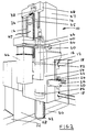
- Figure 2 is a schematic perspective view of a machine tool showing schematically the rotational provision for the ram, and
- Figure 3 is a detailed cross-sectional view showing the means for effecting rotation of the ram.
- As shown schematically in Figure 2, the
machine tool 10 includes acast housing 12 which includes a pair of spaced, parallelvertical rails 14 on which amain transmission carriage 16 may slide up and down in the vertical or Z direction and which is constrained against any rotation. - The
housing 12 is able to move in the horizontal x and y directions as follows. - The
housing 12 is mounted onparallel rails 18 which extend in the y direction and which are secured to theirrelated structure 28 over the full length. Amotor 20 mounted on the housing drives, via abelt 22, aring 24 which threadably engages aball screw 26 which extends parallel with therails 18. The ring is rotatable relative to the housing but is otherwise constrained to move with the housing, whereby rotation of the ring causes the housing to be driven along the ball screw in the y direction with the housing sliding on the rails. The direction of movement in the y direction of the housing can be altered by changing the direction of rotation of the ring. - Each side of the structure 28 (only one of which is shown) is slidably mounted on spaced
parallel rails 30 which extend in the x direction. Driving means 32 (shown schematically) cause the structure to be slid along therails 30 in the required direction. - The
carriage 16 is driven up and down in the z direction by amotor 34 mounted on the housing which rotates aball screw shaft 35 via abelt 38 in the required direction. Thecarriage 16 is suspended on the shaft 36 and threadably engages that shaft which, by rotation, causes the carriage to slide on therails 14. - The
carriage 16 supports, and carries with it in the vertical direction, adrive shaft 40 and aram 42 through which theshaft 40 extends. Theshaft 40 is rotatably driven by amotor 44 mounted on the carriage which drives apulley 46 connected to the top of theshaft 40. - In order to enable the ram, carriage and shaft to move up and down relative to the housing, the upper part of the housing is in the form of an arch having upwardly extending spaced
sides 47 connected at their upper ends by atop 48. - The lower end of the housing includes a
cylindrical guide passage 54 within which the ram is able to slide up and down in the vertical direction and within which the ram can rotate as described later. The cylindrical guide passage is lined with a layer including at least some plastics. The ram is hardened and precision ground. - Figure 3 is a detailed cross-sectional view through the
ram 42 and theshaft 40 in the region of their co-extent with the carriage. All of the components shown in Figure 3 are constrained to move together with the carriage in the z direction. - The
pulley 46 which drives theshaft 40 is shown at the top of the figure. Theshaft 40 is rotatably supported inbearings 56 mounted in the carriage and thecylindrical shaft 40 extends downwardly through theram 42 and is rotatably supported by further bearings (not shown) towards the bottom of the ram. - The
ram 42 is itself rotatable, separate from theshaft 40, upon operation of a motor 60 (shown schematically in Figure 2) which drives aworm 62, as shown in Figure 3. Theworm 62 engages aworm wheel 64 which surrounds theram 42 and is fast therewith in order to cause the ram to rotate about the z axis. The ram may rotate in either direction in dependence upon the direction of rotation of the worm. - A thrust and journal bearing 65 is located just above the wormwheel and the bearing acts on the periphery of the ram. The
bearing 65 transfers the thrust from the cutting tool through the ram up into the sledge and constrains the ram to rotate about the required axis. Thebearing 65 thereby imparts both axial and rotational stiffness to the ram. - The lower end of the ram is arranged to engage a tool unit from a tool unit store such as a carousel unit in a conventional manner. The downwardly facing surface of the ram includes sockets into which studs from a tool unit can enter and locations devices to accurately align and secure the tool unit to the ram.
- As shown in Figure 3,
electrical services 64 andhydraulic fluid services 66 are connected to the ram to enable operations of the ram, and in particular the pick up and release of tool units from the bottom of the ram to be performed. Theshaft 40 is arranged to engage with a socket in a tool unit in order to be able to cause a tool mounted on an output shaft of a tool unit to rotate. The tool of the tool unit may rotate about an axis coincident with or parallel to the axis of theram 42 or may rotate about an axis extending at any angle to the axis of rotation of theram 42. - It will be appreciated that the precise angular position of the
ram 42 relative to the housing will be important in certain circumstances such as when the tool of the tool unit is rotating and being advanced in a direction in the horizontal plane. In order to ensure the precise angular position of the ram, ahirth ring 68 surrounds theram 42 and is able to engage with downwardly extendingteeth 70 secure with theram 42 in order to bring the ram into the required angular position and maintain the ram in that position. Thehirth ring 68 is connected to asupport 72 by aflexible arm 74. Apiston 76 is connected to the hirth ring and, upon pressurisation of achamber 78, can move downwardly in order to disengage thehirth ring 68 from the teeth of the ram (in which position the ram may rotate) or, upon pressurisation of achamber 80, can move upwardly to cause thehirth ring 68 to engage the teeth or the ram (to prevent the ram from rotating and to bring the ram into the precise angular orientation required). - It can be seen from Figure 2 that the diameter of the bottom of the ram is relatively very small as that portion of the ram extending beneath the housing is caused to rotate and reciprocate by parts located away from the bottom region. Thus the machine tool can be used to bore out a relatively small hole in a workpiece. That machining may comprise mounting the tool unit on the end of the ram having an output shaft extending in the horizontal or any other required direction. Rotation of the
shaft 40 then causes rotation of the cutting tool about its axis. At the same time as the cutting tool is rotating about its axis and cutting into the walls of the workpiece the ram can be rotated about its axis to cause the output shaft of the tool unit to rotate in a horizontal plane. If required, the housing can also be moved in the x and y directions, separately or together. Furthermore, the ram can move downwardly into the feature being cut to enable the machine tool to cut workpieces which are relatively deep in the z direction. - The ram can be clamped in the housing by hydraulically operating clamps 82 located at either end of the passage way in the housing, as shown in Figure 3 to provide maximum stiffness to the ram for instance during certain high performance machining operations. When the ram is clamped it may still rotate but the clamp ensures that the axis of rotation is not deflected.
- The ram is that part of the device which carries the tool (either directly or indirectly) towards and away from a workpiece and which also absorbs or reacts against the forces tending to deflect a tool from the intended path of milling or cutting.
- The ram on a milling machine is a cantilevered structure which supports the spindle and provides accurate location and support to a variety of attachable auxiliary spindle heads on its forward face which are designed to satisfy a variety of particular machining operations.
- The ram is required to traverse the machine spindle such that its axis follows a precise straight line perpendicular to the X Y Plane of the machine tool with a feed mechanism of such stiffness as to provide for all of the machining operations required, either from the machine spindle directly, or from the variety of attachable auxiliary spindle heads which are supported by it.
- The ram is also required to provide such axial, transverse and torsional stiffness for all of the machining operations required, either from the machine spindle, or from the variety of attachable auxiliary spindle heads which are supported by it when fed in any required combination of Traverses X Y Z.
Claims (13)
- A machine tool arrangement including a housing (12), a ram (42) and a drive shaft (40), the drive shaft extending through the ram and being rotatable relative to the ram (42), the ram being movable translationally and pivotally, relative to the housing, relative translational movement of the ram and the housing being arranged to cause the operative position of a tool of the tool unit to advance to or retract, at least a part of the ram including a cylindrical outer surface and at least a part of the housing including an inwardly facing cylindrical surface (54), the cylindrical surfaces of the ram and the housing comprising co-operating portions which enable the ram to move translationally and pivotally relative to the housing, characterised in that the ram includes tool unit engaging means which enable the ram to be connected to a tool unit whereby when the ram is connected to a tool unit, pivotal movement of the ram relative to the housing is arranged to alter the orientation of the rotational axis of a tool in the tool unit relative to the rotational axis of the drive shaft, and rotational movement of the drive shaft is arranged to cause a tool of the tool unit to rotate about the axis of the tool, the ram (42) being connected to an intermediate portion (16) which intermediate portion is slidably mounted on the housing (12), the intermediate portion (16) including drive means (60,62) arranged to cause the ram to rotate relative to the housing with the drive shaft being arranged to be driven by further drive means (44,46) arranged to move with the intermediate portion (16).
- An arrangement as claimed in Claim 1 in which the housing includes clamping means (82) which are selectively operable to clamp the ram in the housing to ensure that the axis of rotation is not deflected.
- An arrangement as claimed in Claim 2 in which the clamping means (82) are arranged to co-operate with the ram at two spaced locations.
- An arrangement as claimed in any preceding claim in which the connection of the ram (42) with the intermediate portion (16) is located on the opposite side of the co-operating portions of the ram and housing to that on which the output of the drive shaft (40) is located.
- An arrangement as claimed in any preceding claim in which the intermediate portion (16) and the ram (42) include locking means (68,70) which are operable to prevent rotation of the ram relative to the intermediate portion.
- An arrangement as claimed in any preceding claim in which the drive shaft (40) extends beyond at least one end of the ram.
- An arrangement as claimed in any preceding claim in which the housing (12) is movable about at least one axis extending transversely to the direction in which the ram (42) is movable translationally relative to the housing.
- A method of operating a machine tool arrangement including a housing (12), a ram (42) and a drive shaft (40) extending through the ram comprising rotating the drive shaft relative to the ram to cause a tool of a tool unit to rotate about the axis of the tool and moving the ram translationally and pivotally relative to the housing, with relative translational movement of the ram and the housing advancing or retracting a tool of the tool unit, whereby an outwardly facing cylindrical surface of the ram co-operates with an inwardly facing cylindrical surface of the housing during both relative translational and pivotal movement, characterised in that when the ram is moved pivotally relative to the housing the orientation of the axis of rotation of the tool is altered relative to the rotational axis of the drive shaft (40) and rotational movement of the drive shaft causes the tool of the tool unit to rotate about the axis of the tool, with an intermediate portion being connected to the ram and being slidably mounted on the housing with drive means on the intermediate portion causing the ram to rotate relative to the housing, the drive shaft being driven by further drive means that move with the intermediate portion.
- A method as claimed in Claim 8 comprising moving the ram (42) simultaneously both translationally and pivotally relative to the housing.
- A method as claimed in either of Claims 8 or 9 comprising causing a surface of the ram (42) to slide and pivot against a surface (54) of the housing.
- A method as claimed in any of Claims 8 to 10 comprising causing rotation of a tool with the drive shaft (40) and simultaneously causing translational or pivotal movement or both of the ram whilst a workpiece is being machined with a tool.
- A method as claimed in any of Claims 8 to 11 comprising applying a clamping means to increase the stiffness between the ram and the housing.
- A method of operating a machine tool arrangement as claimed in any of Claims 8 to 12 when using a machine tool arrangement as claimed in any of Claims 1 to 7.
Applications Claiming Priority (4)
| Application Number | Priority Date | Filing Date | Title |
|---|---|---|---|
| GB909024483A GB9024483D0 (en) | 1990-11-10 | 1990-11-10 | Improvements in or relating to machine tools |
| GB9024483 | 1990-11-10 | ||
| PCT/GB1991/001899 WO1992008573A2 (en) | 1990-11-10 | 1991-10-30 | Improvements in or relating to machine tools |
| US08/059,909 US5388934A (en) | 1990-11-10 | 1993-05-10 | Machine tools |
Publications (2)
| Publication Number | Publication Date |
|---|---|
| EP0556226A1 EP0556226A1 (en) | 1993-08-25 |
| EP0556226B1 true EP0556226B1 (en) | 1997-05-02 |
Family
ID=26297933
Family Applications (1)
| Application Number | Title | Priority Date | Filing Date |
|---|---|---|---|
| EP91918862A Expired - Lifetime EP0556226B1 (en) | 1990-11-10 | 1991-10-30 | Improvements in or relating to machine tools |
Country Status (8)
| Country | Link |
|---|---|
| US (1) | US5388934A (en) |
| EP (1) | EP0556226B1 (en) |
| JP (1) | JPH06501427A (en) |
| AU (1) | AU8749891A (en) |
| DE (1) | DE69125944T2 (en) |
| ES (1) | ES2101757T3 (en) |
| GB (1) | GB9024483D0 (en) |
| WO (1) | WO1992008573A2 (en) |
Families Citing this family (4)
| Publication number | Priority date | Publication date | Assignee | Title |
|---|---|---|---|---|
| US20070071545A1 (en) * | 2005-08-26 | 2007-03-29 | Honeywell International, Inc. | Lubricated Hirth serration coupling |
| DE102013012765B4 (en) * | 2013-07-30 | 2025-07-03 | Schuster Maschinenbau Gmbh | Spindle unit for a machining device with a spindle lock |
| US20180000827A1 (en) | 2014-12-19 | 2018-01-04 | Synthon B.V. | Pharmaceutical composition comprising gefitinib |
| CN111906553B (en) * | 2020-07-06 | 2021-12-07 | 蚌埠市富瑞达机床机械制造有限公司 | Liftable machine tool for machining precision instrument |
Family Cites Families (12)
| Publication number | Priority date | Publication date | Assignee | Title |
|---|---|---|---|---|
| US2722161A (en) * | 1952-04-15 | 1955-11-01 | Machines Outils Et D Outil Pro | Turret-head for machine-tools with a rotary spindle |
| DE1194226B (en) * | 1958-08-30 | 1965-06-03 | Reinhard Bohle K G Werkzeugmas | Device for fixing a displaceable quill in machine tools, in particular milling machines |
| DE1295980B (en) * | 1963-06-04 | 1969-05-22 | Honsberg Geb | Fine boring unit |
| DE1271500B (en) * | 1966-01-04 | 1968-06-27 | Froriep Gmbh Maschf | Slide or slide for machine tools, especially vertical lathes |
| DE1552393B1 (en) * | 1966-10-31 | 1969-10-16 | Froriep Gmbh Maschf | Heavy machine tool |
| US3735459A (en) * | 1970-08-28 | 1973-05-29 | W Allen | Multiple axis work head-with dual in line work spindles as disclosed |
| IT1079242B (en) * | 1977-05-27 | 1985-05-08 | Innocenti Santeustacchio Spa | MILLING MACHINE |
| DE8336030U1 (en) * | 1983-12-15 | 1985-05-23 | Werkzeugmaschinenfabrik Adolf Waldrich Coburg Gmbh & Co, 8630 Coburg | DEVICE FOR SWIVELING A TOOL-RECEIVING DEVICE, IN PARTICULAR AN ANGLE MILLING HEAD, AT THE FREE (LOWER) END OF A MILLING SPINDLE SLIDE |
| US4557645A (en) * | 1984-02-27 | 1985-12-10 | Colt Industries Operating Corporation | Tooling attachment adaptor assembly |
| US4570313A (en) * | 1984-12-31 | 1986-02-18 | G. A. Gray Division, The Warner & Swasey Company | Spindle lock-up device |
| JPH0643006B2 (en) * | 1985-11-12 | 1994-06-08 | 豊田工機株式会社 | Attachment tool attachment / detachment device |
| JP2662018B2 (en) * | 1989-02-27 | 1997-10-08 | 東芝機械株式会社 | Attachment attachment / detachment device |
-
1990
- 1990-11-10 GB GB909024483A patent/GB9024483D0/en active Pending
-
1991
- 1991-10-30 WO PCT/GB1991/001899 patent/WO1992008573A2/en not_active Ceased
- 1991-10-30 ES ES91918862T patent/ES2101757T3/en not_active Expired - Lifetime
- 1991-10-30 JP JP3517144A patent/JPH06501427A/en active Pending
- 1991-10-30 EP EP91918862A patent/EP0556226B1/en not_active Expired - Lifetime
- 1991-10-30 AU AU87498/91A patent/AU8749891A/en not_active Abandoned
- 1991-10-30 DE DE69125944T patent/DE69125944T2/en not_active Expired - Fee Related
-
1993
- 1993-05-10 US US08/059,909 patent/US5388934A/en not_active Expired - Fee Related
Also Published As
| Publication number | Publication date |
|---|---|
| JPH06501427A (en) | 1994-02-17 |
| GB9024483D0 (en) | 1991-01-02 |
| ES2101757T3 (en) | 1997-07-16 |
| US5388934A (en) | 1995-02-14 |
| AU8749891A (en) | 1992-06-11 |
| WO1992008573A3 (en) | 1992-07-09 |
| WO1992008573A2 (en) | 1992-05-29 |
| EP0556226A1 (en) | 1993-08-25 |
| DE69125944T2 (en) | 1997-09-11 |
| DE69125944D1 (en) | 1997-06-05 |
Similar Documents
| Publication | Publication Date | Title |
|---|---|---|
| US9162289B2 (en) | Machine tool apparatus and method | |
| US5346343A (en) | Milling head | |
| CN110549166B (en) | Multifunctional movable beam combined machining center for turning, milling, grinding, boring and drilling | |
| KR101689404B1 (en) | Combined lathe and processing method of work | |
| US3513517A (en) | Machining of large hollow cylindrical workpieces | |
| CN110227946B (en) | Six-axis boring and milling machine tool | |
| NO854417L (en) | GRINDING HEAD. | |
| EP0408264B1 (en) | A structural improvement for main shaft of tooling machine | |
| CN105537956A (en) | Hub dead head cutting and drilling integrated machine | |
| CN210208661U (en) | Hard rail compound lathe | |
| CN220128095U (en) | Turning and milling integrated machine | |
| US7721410B2 (en) | Machine tool comprising a clamping device on both sides | |
| US5388934A (en) | Machine tools | |
| CN211804803U (en) | Vertical and horizontal combined machining equipment | |
| EP0406494B1 (en) | An improvement for tool milling machine or the like type complex processing machine | |
| CN1261280C (en) | Multifunctional deep hole working machine | |
| US3200470A (en) | Machine tool | |
| CN116638379B (en) | Integrated processing machine tool | |
| CN219901075U (en) | Rotary positioning mechanism of numerical control machine tool | |
| EP0652074B1 (en) | Machining head for mechanically machining boards, in particular printed circuit boards | |
| CN220051005U (en) | Automatic material processing device for flexible production and manufacturing line | |
| CN110605581A (en) | Upper chip removal deep hole machining mechanism | |
| CN210703559U (en) | Six-shaft boring and milling machine tool | |
| CN211489631U (en) | Novel cross tool table for numerical control core walking vehicle | |
| CN116475848A (en) | Multi-working-procedure integrated machine tool |
Legal Events
| Date | Code | Title | Description |
|---|---|---|---|
| PUAI | Public reference made under article 153(3) epc to a published international application that has entered the european phase |
Free format text: ORIGINAL CODE: 0009012 |
|
| 17P | Request for examination filed |
Effective date: 19930521 |
|
| AK | Designated contracting states |
Kind code of ref document: A1 Designated state(s): BE CH DE ES FR GB IT LI NL SE |
|
| 17Q | First examination report despatched |
Effective date: 19950118 |
|
| GRAG | Despatch of communication of intention to grant |
Free format text: ORIGINAL CODE: EPIDOS AGRA |
|
| GRAH | Despatch of communication of intention to grant a patent |
Free format text: ORIGINAL CODE: EPIDOS IGRA |
|
| GRAH | Despatch of communication of intention to grant a patent |
Free format text: ORIGINAL CODE: EPIDOS IGRA |
|
| RAP1 | Party data changed (applicant data changed or rights of an application transferred) |
Owner name: MARBAIX LAPOINTE LIMITED |
|
| GRAA | (expected) grant |
Free format text: ORIGINAL CODE: 0009210 |
|
| AK | Designated contracting states |
Kind code of ref document: B1 Designated state(s): BE CH DE ES FR GB IT LI NL SE |
|
| PG25 | Lapsed in a contracting state [announced via postgrant information from national office to epo] |
Ref country code: NL Free format text: LAPSE BECAUSE OF FAILURE TO SUBMIT A TRANSLATION OF THE DESCRIPTION OR TO PAY THE FEE WITHIN THE PRESCRIBED TIME-LIMIT Effective date: 19970502 Ref country code: LI Effective date: 19970502 Ref country code: FR Effective date: 19970502 Ref country code: CH Effective date: 19970502 Ref country code: BE Effective date: 19970502 |
|
| REG | Reference to a national code |
Ref country code: CH Ref legal event code: EP |
|
| REF | Corresponds to: |
Ref document number: 69125944 Country of ref document: DE Date of ref document: 19970605 |
|
| REG | Reference to a national code |
Ref country code: ES Ref legal event code: FG2A Ref document number: 2101757 Country of ref document: ES Kind code of ref document: T3 |
|
| PG25 | Lapsed in a contracting state [announced via postgrant information from national office to epo] |
Ref country code: SE Effective date: 19970802 |
|
| PGFP | Annual fee paid to national office [announced via postgrant information from national office to epo] |
Ref country code: GB Payment date: 19970827 Year of fee payment: 7 |
|
| NLV1 | Nl: lapsed or annulled due to failure to fulfill the requirements of art. 29p and 29m of the patents act | ||
| EN | Fr: translation not filed | ||
| PGFP | Annual fee paid to national office [announced via postgrant information from national office to epo] |
Ref country code: ES Payment date: 19971006 Year of fee payment: 7 |
|
| PGFP | Annual fee paid to national office [announced via postgrant information from national office to epo] |
Ref country code: DE Payment date: 19971107 Year of fee payment: 7 |
|
| REG | Reference to a national code |
Ref country code: CH Ref legal event code: PL |
|
| PLBE | No opposition filed within time limit |
Free format text: ORIGINAL CODE: 0009261 |
|
| STAA | Information on the status of an ep patent application or granted ep patent |
Free format text: STATUS: NO OPPOSITION FILED WITHIN TIME LIMIT |
|
| 26N | No opposition filed | ||
| PG25 | Lapsed in a contracting state [announced via postgrant information from national office to epo] |
Ref country code: GB Free format text: LAPSE BECAUSE OF NON-PAYMENT OF DUE FEES Effective date: 19981030 |
|
| PG25 | Lapsed in a contracting state [announced via postgrant information from national office to epo] |
Ref country code: ES Free format text: LAPSE BECAUSE OF NON-PAYMENT OF DUE FEES Effective date: 19981031 |
|
| GBPC | Gb: european patent ceased through non-payment of renewal fee |
Effective date: 19981030 |
|
| PG25 | Lapsed in a contracting state [announced via postgrant information from national office to epo] |
Ref country code: DE Free format text: LAPSE BECAUSE OF NON-PAYMENT OF DUE FEES Effective date: 19990803 |
|
| REG | Reference to a national code |
Ref country code: ES Ref legal event code: FD2A Effective date: 19991113 |
|
| PG25 | Lapsed in a contracting state [announced via postgrant information from national office to epo] |
Ref country code: IT Free format text: LAPSE BECAUSE OF NON-PAYMENT OF DUE FEES;WARNING: LAPSES OF ITALIAN PATENTS WITH EFFECTIVE DATE BEFORE 2007 MAY HAVE OCCURRED AT ANY TIME BEFORE 2007. THE CORRECT EFFECTIVE DATE MAY BE DIFFERENT FROM THE ONE RECORDED. Effective date: 20051030 |