EP0556071B1 - Ticket printer - Google Patents
Ticket printer Download PDFInfo
- Publication number
- EP0556071B1 EP0556071B1 EP93301067A EP93301067A EP0556071B1 EP 0556071 B1 EP0556071 B1 EP 0556071B1 EP 93301067 A EP93301067 A EP 93301067A EP 93301067 A EP93301067 A EP 93301067A EP 0556071 B1 EP0556071 B1 EP 0556071B1
- Authority
- EP
- European Patent Office
- Prior art keywords
- ticket
- blanks
- feed
- medium
- printer
- Prior art date
- Legal status (The legal status is an assumption and is not a legal conclusion. Google has not performed a legal analysis and makes no representation as to the accuracy of the status listed.)
- Expired - Lifetime
Links
Images













Classifications
-
- G—PHYSICS
- G07—CHECKING-DEVICES
- G07B—TICKET-ISSUING APPARATUS; FARE-REGISTERING APPARATUS; FRANKING APPARATUS
- G07B1/00—Machines for printing and issuing tickets
Definitions
- the former airline ticket printer has an advantage in that the precut ticket blanks can be easily magnetically recorded and printed. These tickets are a sort of high-priced securities, and so there is a need of managing the blanks therefor. However, not only is it difficult to manage such separate ticket blanks, but they are also likely to be missing by wrongdoing or in error. In addition, much difficulty is encountered in finding them, when missing.
- the pre-feeder unit 4 is designed such that each ticket blank la previously cut and separated there is put in a ready-for-further-feeding state and, by an issuance order, is fed to the MS unit 5, thereby improving the issuance speed.
- a right-hand frame 48' is provided with a biasing spring 49 that serves to engage each cut ticket blank 1a with a left-hand frame 48, so that it can be put in order in the widthwise direction.
- the magnet MG1 is first driven to close up the retracted pinch roller 44a so as to retract the cutter 47a, as shown in Fig. 12(B).
- the pulse motor PM 3 for the cutter is rotated counterclockwise (or in the CCW direction) to move the link 46 by the cam 45 in the right-handed direction in this figure, thereby retracting the cutter 47a.
- the rotation of this pulse motor PM 3 is put off when the output of the sensor S4 is low, indicating that the cutter has reached its retracted position, as shown in Fig. 11.
- the medium 1 can then be cut easily and surely, because tension is imparted to the medium 1, as shown in Fig. 13(A), and because the perforation 17 in the medium 1 is cut on both its sides, as shown at 18.
- the manually-inserting portion 5b includes a shutter 56 located on an inserting port 21 and a magnet MG3 that opens the shutter 56 in association with hand insertion, thereby switching the gate 54 over to the hand-inserting portion 4b.
- the horizontal location of the thermal head 60 is assured by engaging the pin 603 extending from the center of the bracket 600 within the positioning groove 609 in the center of the hanger 608 and biasing the opposite side thereof by means of the sheet spring 604, as shown in Fig. 19, thereby making the positioning of the thermal head 60 easier.
- the attachment of the swing lever 606 to the bracket 600 is achieved in much the opposite manners as mentioned above, i.e., by fitting the pin 603 extending from the bracket 600 into the positioning groove 610 in the hanger 608 and then forcing therein the side of the bracket 600 on which the sheet spring 604 is attached.
- the second procedure may also be achieved by using a stepping motor for driving the driving pulley in place of the encoder, but there is a need of increasing or decreasing the stepping number of the motor.
- Fig. 27 represents the functions of CPU 70 of Fig. 26 in a blocked form, and the functions of the control block 70 will now be explained with reference thereto.
Landscapes
- Physics & Mathematics (AREA)
- General Physics & Mathematics (AREA)
- Electronic Switches (AREA)
- Ticket-Dispensing Machines (AREA)
Description
- The present invention relates generally to a ticket printer and, more particularly, to a ticket printer for issuing a valuable ticket in which ticketing data is both magnetically recorded and printed by recording and printing ticketing data on it.
- In airline and other industries, a reservation and ticketing system for airline or other tickets, called a computer reservation system or CRS for short, has been built up so as to deal with intensive passenger-conscious services. A problem of vital importance for such a system designed to accommodate a recently increasing number of passengers is to make its services (for reservation and fare adjustment) efficient.
- For that reason, the use of airline tickets provided with magnetic strips or stripes so as to control these services in bulk, called automated ticket/boarding pass or ATB for short, is now spreading. These tickets are required to have a high storage stability of printed data and to have the ability to be printed easily as well. A ticket printer for them for its part is required to make ticket management easy and to render ticketing less time- and labor-consuming as well.
- Tickets issued from a conventional ticket printer have made use of plain paper and been printed on wire-dot, electrophotographic and other printing systems. The wire-dot printing system involves some grave problems such as (1) loud noise, (2) low print resolution and (3) slow printing speed, and the electrophotographic printing system has again some serious problems such as (1) an increase in hardware size, (2) a rise in hardware cost and (3) susceptibility to environmental changes (printing is difficult at high humidity in particular). In recent years, hardware working on a thermal-dot printing system making use of a heat transfer ink ribbon has been developed.
- This thermal-dot printing system making use of a heat transfer ink ribbon makes no noise, has a high print resolution and a high printing speed, achieves reductions in hardware size and cost and dispenses with any maintenance, and so lends itself well to issuing airline tickets.
- However, some serious problems with the conventional thermal-dot printing system making use of a heat transfer ink ribbon are that (1) the heat transfer ink ribbon costs much and incurs some considerable expense for maintenance, and (2) the heat transfer ink ribbon is troublesome to handle, because it must be replaced by new one whenever a certain number of prints are obtained.
- Consequently, it is now desired to use printing hardware working on a direct thermal printing system - in which case heat-sensitive paper is directly printed - and making no use of any heat transfer ink ribbon. In the case of airline tickets that are a sort of securities, however, there are the following problems.
- (1) Generally, the thermal-printing paper is a paper that is obtained by coating a heat-sensitive layer comprising a leucodye, a color developer and a binder onto a paper substrate at a thickness of a few µm. When heated by a thermal printing element, the leucodye and color developer are fused to give rise to a color-developing chemical reaction. However, this color-developing zone, when stored over an extended period, disappears, thus rendering the thermally printed paper valueless.
- (2) A printed thermal-printing paper, when coming into contact with an organic solvent such as alcohol, a plasticizer and oils and fats, breaks up the chemical reaction, causing the color-developing zone to disappear.
- Conventional airline ticket printers have been broken down into two types, one in which a stock of precut ticket blanks are fed out one by one for magnetic recording and printing, and the other in which a stock of continuous paper blank is magnetically recorded and printed.
- The former airline ticket printer has an advantage in that the precut ticket blanks can be easily magnetically recorded and printed. These tickets are a sort of high-priced securities, and so there is a need of managing the blanks therefor. However, not only is it difficult to manage such separate ticket blanks, but they are also likely to be missing by wrongdoing or in error. In addition, much difficulty is encountered in finding them, when missing.
- The latter airline ticket printer has an advantage in that the continuous ticket blank can conveniently be managed, because whether or not something wrong is occuring can be easily determined by finding the presence of cutouts. However, it is difficult to make magnetic records and prints on a continuous form of ticket blank, and this form of ticket blank costs much time and labor, because it is required for an operator to separate it into individual tickets and hand them to passengers.
- WO90/08944 discloses a ticket dispensing printer in which fan-folded tickers are separated by a burster blade. During bursting the rollers holding the card stock are held so that they cannot rotate in response to the tension forces created by the downwards movement of the burster blade.
- EP 0416795 describes a ticket printer having a bursting blade. In one embodiment the feed rollers are driven in opposite directions to tension the paper during cutting with the bursting blade.
- The invention envisages the use of a valuable form of ticket which, even when printed using a direct thermal printing system, does not lose the printed information.
- The ticket permits ticketing data to be magnetically recorded and printed, and may include a base, a heat-sensitive layer applied on one side of the base, a protective layer applied on the heat-sensitive layer and a magnetic recording layer applied on the other side of the base.
- Because the protective layer is applied to the heat-sensitive layer, such tickets can be proof against contact with solvents, plasticizers, and so on. Besides, the ticket can be used in the form of a security, because the color-developing zone will not be erased, even when formed by a simple direct thermal printing system, and so is high in terms of storage stability.
- Because the magnetic recording layer is applied on the opposite side of the base to the side on which the heat-sensitive layer is formed and so the heat-sensitive layer is available over the full side to be printed, it is possible to make effective use of a ticket that has a limited area. With such tickets the magnetic recording layer is not affected by the heat of a thermal recording element, and so that data magnetically recording there is invariable; it is therefore possible to make sufficient prints and record the magnetic data reliably.
- The invention is intended to provide a ticket printer for issuing such tickets. In particular some embodiments of the invention provide a ticket printer which enables ticket blanks to be easily managed and which is capable of issuing a valuable form of tickets individually. Ticket printers according to other embodiments of the invention may be so compact in size that they can be located between desks.
- According to the invention there is provided a ticket printer for magnetically recording and printing ticketing data on ticket blanks for issuance, including:
- ticket blank holder means for holding a continuous form of medium having perforations that can be separated along the perforations into individual ticket blanks;
- magnetic recording means for magnetically recording ticket data on a magnetic layer of the individual ticket blanks;
- printing means for printing ticket data on each ticket blank for issuance; and
- pre-feeder means for feeding the continuous medium from the ticket blank holder means, cutting the continuous medium along the perforation into the said individual ticket blanks and feeding these individual ticket blanks to the magnetic recording means, the pre-feeder means including:
- feed rollers for feeding the continuous medium and the individual ticket blanks; and a cutter provided between the feed rollers, for cutting the continuous medium as aforesaid;
- in which the pre-feeder means further includes driving means for forwardly driving both feed rollers when said continuous medium is to be fed and is further adapted to hold the first feed roller in the feed path and forwardly drive the second feed roller in the feed path when the continuous medium is to be cut, thereby applying tension to the medium on both sides of the perforation.
- This ticket printer makes magnetic recording and printing easy and dispenses with separating tickets after issuance, because, even when a continuous form of medium is used, it is cut through the pre-feeder unit to individual ticket blanks and these individual ticket blanks are magnetically recorded and printed, and so the valuable ticket blanks can be easily controlled as a continuous form of medium and, besides, can be magnetically recorded and printed individually.
- Other features and advantages of the present invention will be apparent from the following description taken in conjunction with the accompanying drawings.
-
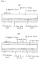
- Figure 1 is a sectional view of one example of an airline ticket ;
- Figure 2 is an upper view of the airline ticket of Fig. 1,
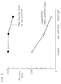
- Figure 3 is a characteristic graph that shows the storage stability of the airline ticket of Fig. 1,
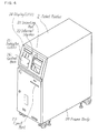
- Figure 4 is an illustration of the appearance of the airline ticket printer according to a comparative example
- Figure 5 is a perspective view of the airline ticket printer of Fig. 4 in which all the units are drawn out,
- Figure 6 is a sectional view of the airline ticket printer of Fig. 4,
- Figure 7 is a sectional view of the pre-feeder unit of the airline ticket printer of Fig. 6,
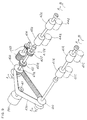
- Figure 8 is an exploded perspective view of the pre-feeder unit of Fig. 7,
- Figure 9 is a perspective view of the pre-feeder unit of Fig. 8 that is in a finished-up state,
- Figure 10 is an illustration showing part of the pre-feeder unit of Fig. 7,
- Figure 11 is a performance time chart of the pre-feeder unit of Fig. 7,
- Figure 12 is a first illustration of how the pre-feeder unit of Fig. 7 works,
- Figure 13 is a second illustration of how the pre-feeder unit of Fig. 7 works,
- Figure 14 is a sectional view of the MS unit of the airline ticket printer of Fig. 6,
- Figure 15 is a perspective view of the MS unit of Fig. 14,
- Figure 16 is a view illustrating part of the MS unit of Fig. 14,
- Figure 17 is a sectional view of the printer unit of the airline ticket printer of Fig. 6,
- Figure 18 is a front view showing part of the printer unit of Fig. 17,
- Figure 19 is a view illustrating part of the printer unit of Fig. 17,
- Figure 20 is a representation that illustrates the attachment or detachment of the head in the printer unit of Fig. 17,
- Figure 21 is a view that shows the construction of another pre-feeder unit, shown as another comparative example.
- Figure 22 is an illustration of how the pre-feeder unit of Fig. 21 works,
- Figure 23 is a view that illustrates the construction of an embodiment of the pre-feeder unit,
- Figure 24 is an illustration of how the pre-feeder unit of Fig. 23 works,
- Figure 25 is an illustration of where the MS unit of Fig. 16 starts to write,
- Figure 26 is a block diagram that provides an illustration of how the write start position of the MS unit of Fig. 16 is corrected,
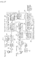
- Figure 27 is a block diagram that illustrates the function of a main controller unit shown in Fig. 26,
- Figure 28 is a flow chart for correcting the write start position of the MS unit of Fig. 16, and
- Figure 29 is an illustration of how the block of Fig. 27 works.
- Referring first to Figs. 1-3, there is shown an airline ticket of the type that may be produced by tne ticket printer according to the invention.
- As illustrated in Fig. 1(A), an airline ticket blank, shown generally by la, comprises a
paper base 13 that is provided on its one (back) side with a heat-sensitive layer 14 having on its surface aprotective layer 15 formed of water-soluble resin. On the opposite (front) side of thepaper base 13 there is provided amagnetic stripe 11. This heat-sensitive layer 14 is composed of an irreversible pigment, a developer and a binder. - Thus, the provision of the
protective layer 15 on the surface of the heat-sensitive layer 14 can physically prevent a solvent such as alcohol, a plasticizer, and so on from entering the heat-sensitive layer 14. This in turn makes it possible to prevent a solvent such as alcohol, a plasticizer, and so on from coming into contact with the portion of the heat-sensitive layer 14 that develops color by chemical reactions, thereby breaking up such chemical reactions and so resulting in fade-out. - The irreversible pigment is used as the color-developing dye in the heat-
sensitive layer 14, so that the ticket according to this example can stand up to long-term storage and so is best suited as a reservation ticket. - The
magnetic stripe 11 is provided on the side of thepaper base 13 that is opposite to the side on which the heat-sensitive layer 14 is provided, so that the heat-sensitive layer 14 is available all over the surface for printing, thus assuring adequate printing. In addition, themagnetic stripe 11 is unlikely to receive printing heat directly and so the magnetically recorded data thereon are unlikely to change. - Another example of the ticket shown in Fig. 1(B) follows the construction shown in Fig. 1(A) with the exception that an additional
protective layer 16 is provided on the side of thepaper base 13 with themagnetic stripe 11 formed on it. According to this embodiment, it is possible to prevent solvents, plasticizers, etc., from penetrating into the heat-sensitive layer 14 through thepaper base 13, and so it is possible to improve the storage stability of the ticket further. - As illustrated in Fig. 2, this airliner ticket blank la is in the form of
continuous paper 1 that is provided withfolds 19 perforated, as shown at 17, for its easy separation with suitable equipment. Further, eachperforation 17 is cut in from both edges, as shown at 18, for easier separation of each ticket blank. It is here noted that one ticket blank la is divided by afold 19 from another, and provided with additional two perforations 17', so that a ticket collector can receive the stub when it is used. - As can be seen from Fig. 3 that is a storage stability diagram, a conventional heat-sensitive ticket having no
protective layer 15 decreases in terms of the residual rate of the color-developing zone to 50% with respect to a solvent, 30% with respect to oils and fats and 10% with respect to a plasticizer, but the heat-sensitive ticket of the invention, shown in Fig. 1(A), is of good-enough storage stability, because the residual rate of the color-developing zone is nearly invariable, i.e., 100% with respect to a solvent, 100% with respect to oils and fats and 90% with respect to a plasticizer. - The airliner ticket printer according to a comparative example will now be explained with reference to Figs. 4, 5 and 6.
- Referring first to Fig. 4, there is perspectively shown an airliner ticket printer shown generally at 2. This ticket printer is built up of a
housing 20, aninlet port 21 through which an unrecorded, unprinted ticket blank is inserted for printing and magnetic recording, an internal stacker orhopper 22 for storing printed, magnetically recorded ticket blanks, and anejection port 23 for ejecting the printed, magnetically recorded ticket blanks.Reference numeral 24 represents a display (e.g., a liquid-crystal display - LCD) for guidance and other purposes, 25 an indicator (e.g., a light-emitting diode - LED) for providing an indication of what state the ticket printer is in, and so on, and 26 a control panel that is covered and includes keys for various operations. - Referring then to Figs. 5 and 6, the
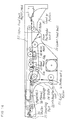
printer 2 includes in its lower portion ticketblank stock holders 3a and 3b in which thecontinuous paper 1 shown in Fig. 2 is set in order and kept in stock. Theprinter 2 further includes apre-feeder unit 4 in which thecontinuous paper 1 fed from the ticketblank stock holders 3a and 3b is cut and separated into individual tickets blanks la and the ticket blanks are put in order in the widthwise direction and then in a ready-for-further-feeding state, an MS (magnetic recording)unit 5 for magnetically recording on themagnetic stripe 11 of each separated ticket blank la ticketing data (for instance, destination, departure and arrival dates and times, flight number, seat number, and so on), and aprinter unit 6 for thermally printing on theside 12, to be printed, of the magnetically recorded ticket blank 1a, ticketing data (for instance, destination, departure and arrival dates and times, flight number, seat number, and so on) for issuance. - Also built in the
printer 2 areslide rails 27a and 27b for pulling out of thehousing 20 the ticketblank stock holders 3a and 3b,pre-feeder unit 4,MS unit 5,printer unit 6, and so on, and areject unit 28 for keeping somedefective tickets 1a, if any, in stock. - In the instant example, individual ticket blanks la are stocked in the form of the
continuous paper 1. This is because the respective ticket blanks la must have been serially numbered owing to being the originals of securities. The tickets being in the form of continuous paper means that pilferage is by no means feasible, unless the paper is cut; in other words, as long as the tickets are in a continuous form, it can be judged that something wrong such as pilferage has not occurred. In the case where ticket blanks are stocked in a separate state, some considerable time and labor are needed for determining whether or not pilferage has occurred, thus making their control difficult. However, if they are in a continuous form, they can then be easily controlled as securities. - On the other hand, some difficulty is involved in feeding continuous paper directly for magnetic recording, and the continuous paper, if ejected, must be cut manually. For these reasons, the printer is designed such that the
continuous paper 1 is cut and separated into individual ticket blanks through thepre-feeder unit 4, and they are then magnetically recorded through theMS unit 5 and finally printed through theprinter unit 6 for issuance. - In addition, the
pre-feeder unit 4 is designed such that each ticket blank la previously cut and separated there is put in a ready-for-further-feeding state and, by an issuance order, is fed to theMS unit 5, thereby improving the issuance speed. - Furthermore, the
printer unit 6 works on a direct printing mode making use of a thermal head, so that printing can be made easily and in a timesaving and laborsaving manner as well. - The ticket printer according to this example is reduced in height and in depth as well by locating the
ticket stock holders 3a and 3b in its lower region and locating the pre-feeder, MS andprinter units pre-feeder unit 4 diagonally to extend the ticket blank feed passage from the lower portion to the back side thereof and then from the back side to the front side thereof. - In order to print and magnetically record data on a manually inserted ticket blank, the ticket blank is inserted into the
MS unit 5 through theinlet port 21 for magnetic recording and then printed through theprinter unit 6 for issuance. The provision of theinternal stacker 22 enables a large quantity of tickets for party travelers, for instance, to be stacked up and issued. - Each part of such an airliner ticket printer will now be explained at great length. Reference will first be made to Figs. 7, 8, 9 and 10.
- As can be seen from Fig. 7, there are provided
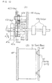
ticket suction ports 40a and 40b through which thecontinuous paper 1 is sucked from the ticketblank stock holders 3a and 3b,feed rollers pinch rollers 41c and 41d for feeding the paper while it is held between them and thefeed rollers ejection rollers pinch rollers 44a and 44b for feeding the paper while it is held between them and therollers rollers timing belts 43a and 43b for rotating therollers - Magnets MG1 and MG2 are provided for engaging or disengaging the
pinch rollers 44a and 44b with or from therollers Reference numeral 45 represents a cam for driving alink 46 linearly, PM3 a pulse motor for rotating thecam 45, 46 a link designed to move linearly by the rotation of thecam link 46 for burst-cutting theperforation 17 in thecontinuous paper 1. S3 represents a sensor for sensing the location of thelink 46, thereby detecting that thecutters 47a and 47b are at their positions available for cutting, and S4 denotes another sensor for sensing the location of thelink 46, thereby detecting that thecutters 47a and 47b are at their retracted positions. - As can be seen from Figs. 8 and 9, the
feed rollers unit frame 48 of thepre-feeder unit 4. Thisfeed roller 41a is provided with agear 410 that meshes with thetiming belt 43a driven by adriving gear 411 of the pulse motor PM1. Similarly, thefeed roller 42a is provided with agear 420 that meshes with thetiming belt 43a, agear 421 integral with thegear 420, agear 422 andauxiliary gears - As illustrated in Fig. 10(A), the
gears feed roller 42a are provided therethrough with a one-way clutch 421a that works only in the direction shown at B in this figure, and thegear 422 is provided therethrough with a one-way clutch 422a as well, which works only in the direction shown at B in this figure. Then, theauxiliary gear 423 meshes with thegear 421, theauxiliary gear 424 meshes with theauxiliary gear 423, and thegear 422 meshes with theauxiliary gear 424. - As can be seen from Fig. 10(A), as the
timing belt 43a is driven in the direction B, the rotations of thegears feed roller 42a by way of the one-way clutch 421a, so that thefeed roller 42a can rotate in the direction B or forwardly. At this time, thegear 422 is rotated in the direction A or backwardly by thegear 421 through the auxiliary gears 423 and 424, but it remains idle by the operation of the one-way clutch 422a. - As the
timing belt 43a is driven in the direction A in Fig. 10(A), thegears gear 422 to rotate by thegear 421 by way of theauxiliary gears feed roller 42a by the one-way clutch 422a, thereby rotating thefeed roller 42a in the direction B or forwardly in this figure. - Thus, the
feed roller 42a can be rotated in the direction B or forwardly, irrespective of whether thetiming belt 43a is fed in the direction A (forwardly) or B (backwardly), enabling the medium to be fed forwardly. - As illustrated in Fig. 10(B), a right-hand frame 48' is provided with a biasing
spring 49 that serves to engage each cut ticket blank 1a with a left-hand frame 48, so that it can be put in order in the widthwise direction. - While the arrangement shown in Figs. 8-10 has been described chiefly with reference to the suction port 40a that corresponds to the ticket blank holder 3a shown in Fig. 7, it is understood that this is true of the
suction port 40b that corresponds to the ticketblank holder 3b. - How the
pre-feeder unit 4 works will now be explained with reference to Figs. 11, 12 and 13. - In their initial state shown in Fig. 12(A), the
cutters 47a and 47b are at their ready-to-cut positions, and so block up the feed passage. In this state, the operator operates an associated lever, not shown, to retract the pinch roller 41c, and then inserts thecontinuous paper 1 into the suction port 40a until it abuts against the back of thecutter 47a. Thereafter, the operator operates the lever to close up the pinch roller 41c, and then inserts the leading end of thecontinuous paper 1 between thefeed roller 41a and the pinch roller 41c for setting the continuous medium in place. - Then, the magnet MG1 is first driven to close up the retracted
pinch roller 44a so as to retract thecutter 47a, as shown in Fig. 12(B). Subsequently, thepulse motor PM 3 for the cutter is rotated counterclockwise (or in the CCW direction) to move thelink 46 by thecam 45 in the right-handed direction in this figure, thereby retracting thecutter 47a. The rotation of thispulse motor PM 3 is put off when the output of the sensor S4 is low, indicating that the cutter has reached its retracted position, as shown in Fig. 11. - With the pulse motor PM1 for paper feed rotated counterclockwise (or in the forward direction), the
feed rollers 41 and 42a are then rotated in the forward direction by thetiming belt 43a for paper feed. The pulse motor PM1 stops upon theperforation 17 of the medium 1 reaching the location of thecutter 47a. This is because the output of the sensor S1 decreases upon detecting that the leading end of the medium 1 passes by. In this state, theperforation 17 in the medium (continuous paper) 1 is positioned at the location of thecutter 47a. - Then, the PM1 for paper feeding is rotated 2 to 5 steps clockwise CW (or in the direction), as shown in Fig. 13(A). This in turn causes a reversal of the
feed roller 41a and a forward rotation of thefeed roller 42a by the operations of the above-mentioned one-way clutches 421 and 422a shown in Fig. 10, thereby pulling themedium 1 by both thefeed rollers medium 1, thereby making it easy to cut themedium 1. - With no tension imparted to the
medium 1, thecontinuous medium 1 may become loose at the location of the cutter due to a difference in the feed speed between thefeed rollers feed rollers - As shown in Fig. 13(B), the
pulse motor PM 3 for the cutter is further rotated counterclockwise to move thelink 46 by thecam 45 in the left-handed direction in this figure, so that thecutter 47a can beat theperforation 17 of themedium 1 for burst-cutting. - The medium 1 can then be cut easily and surely, because tension is imparted to the
medium 1, as shown in Fig. 13(A), and because theperforation 17 in themedium 1 is cut on both its sides, as shown at 18. - After the cutting of the medium is completed, the
pulse motor PM 1 is rotated 40 steps clockwise (or in the CW direction), as shown Fig. 11. This in turn causes a reversal of thefeed roller 41a and a forward rotation of thefeed roller 42a by the operations of the above-mentioned one-way clutches 421a and 422a shown in Fig. 10, thus separating thecut medium 1a from thecontinuous medium 1 and putting it in a ready-for-further-feeding state on the ejection port side. - After that, as the magnet MG1 is put off, as shown in Fig. 11, the
pinch roller 44a is retracted to enable eachcut medium 1a to be widthwise engaged with the left-hand frame 48 by the biasingspring 49 attached to the right-handed side frame 48', shown in Fig. 10(B). In this manner, the pre-feeding of each ticket blank is completed. - Upon receipt of an issuance command, the sequences from Fig. 12(B) occur, and the
cut medium 1a that is standing ready for further feeding is fed to themagnetic recording unit 5, while thecontinuous medium 1 is fed and cut and then allowed to stand ready for further feeding. - Because the set
continuous paper 1 is precut intoindividual ticket blanks 1a ready for further feeding, each ticket blank 1a can be fed to themagnetic recorder unit 5 just upon receipt of issuance instructions, thereby improving issuance speed. - While the operations of the parts located on the suction port (40a) side corresponding to the ticket blank holder 3a have been described with reference to Figs. 12 and 13, it is understood that those on the suction port (40b) side corresponding to the ticket
blank holder 3b operate similarly. In this case, the cutter-drivingPM 3,cam 45 and link 46 are commonly used. - The
magnetic recording unit 5 will now be explained with reference to Figs. 14, 15 and 16. - As shown in Fig. 14, the MS (magnetic recording)
unit 5 includes a manually-inserting portion 5b for receiving a manually inserted ticket blank, an MS read-write unit 5a for magnetically recording data on themagnetic stripe 11 of the ticket blank and a portion 5c in which the manually inserted ticket blank stands ready for further feeding. As shown in Figs. 14 and 15, anupper feed belt 52 is provided all over the hand-inserting portion 5c, the MS read-write portion 5a and the portion 5c. - The MS read-
write unit 5a is provided with alower feed belt 53 for feeding the ticket blank 1a while it is held between the upper andlower feed belts write head 50 for magnetically recording data on themagnetic stripe 11 of the ticket blank 1a and aread head 51 for read-after-write check. - Further, there are provided a
guide roller 50a opposite to thewrite head 50, aguide roller 51a opposite to the readhead 51, agate 54 for guiding the magnetically recordedticket 1a to theprinter unit 6 or the hand-inserting portion 5b, and adischarge roller 55 for ejecting theticket 1a into theprinter unit 6. - The manually-inserting portion 5b includes a
shutter 56 located on an insertingport 21 and a magnet MG3 that opens theshutter 56 in association with hand insertion, thereby switching thegate 54 over to the hand-inserting portion 4b. - The standby portion 5c includes a
roller 57 opposite to theupper feed belt 52 and a magnet MG4 for moving and engaging theroller 57 toward and with theupper feed belt 52. - As shown in Fig. 16, the MS read-
write unit 5a includes a biasingspring 58 attached to a right-hand frame 59', which serves to bias the ticket blank 1a a left-hand frame (guide) 59 at the write and readheads - Explaining this operation, the ticket blank 1a fed from the
pre-feeder unit 4 is supplied, while it is sandwiched between the upper andlower feed belts write head 50 where data are magnetically recorded on themagnetic stripe 11 of the ticket blank 1a. Then, it is further fed to the readhead 51 where the data are read, and ejected into the printer unit through theejection roller 55 by way of thegate 54. - In this case, it is assured that the data can be written onto the magnetic stripe by the
write head 50 and read therefrom by the readhead 51, because the ticket blank 51a is carried while it is biased by the biasingspring 58 against the left-hand guide 59 on the side of which there are theheads feed belts magnetic stripe 11 by thehead 50 and read therefrom by thehead 51. - In the case of the manually inserted ticket blank, on the other hand, the
shutter 56 is opened by the magnet MG3 and thegate 54 is actuated to connect the hand-inserting portion 5b with the MS read-write portion 5a. Then, the ticket blank 1a is fed by theupper feed belt 52 through the insertingport 21 and the read-write portion 5a to the standby portion 5c where it stands ready for further feeding. - Upon receiving an issuance order, the magnet MG4 of the standby portion 5c is driven to feed the ticket blank 1a to the MS read-
write unit 5a while theroller 57 is engaged with theupper belt 52. Through the MS read-write unit 5a, the ticket blank 1a is fed while it is sandwiched between the lower andlower belts magnetic stripe 11 of the ticket blank 1a and read therefrom by the readhead 51. Then, the ticket blank 1a is ejected by theejection roller 55 into theprinter unit 6 by way of thegate 54. - The
printer unit 6 will now be explained with reference to Fig. 17. - In Fig. 17,
reference numeral 60 represents a line thermal head for the thermal printing of the heat-sensitive ticket blank including the protective layer, shown in Fig. 1, 61 a platen that is located in opposition to thethermal head 60, 62 a lever for keeping the space between thethermal head 60 and theplaten 61 constant, and MG5 a magnet for driving thelever 62. -
Reference numeral 63 stands for a feed belt for feeding the printedticket 1a toward theejection port 23, 64 a feed belt for carrying the printedticket 1a to the hopper (internal stacker) 22, 65 a gate for guiding the printedticket 1a to thehopper 22 or thedischarge port 23, and MG6 a magnet for driving thegate 65 for switching-over. -
Reference numeral 66 denotes a gate for guiding the printedticket 1a to thereject box 28 or theejection portion 23, MG7 a magnet for driving thegate 66 for switching-over, and PM4 a pulse motor for driving thefeed belt 64, etc. - Explaining this operation, the ticket blank 1a fed from the
MS unit 5 strikes on thethermal head 60 where its leading end is properly positioned and whence it is fed to theplaten 61, in the course of which it is linearly printed. - In order to eject the ticket blank 1a into the
ejection port 23, the magnet MG6 is put on to locate thegate 65 at a position shown by a dotted line in Fig. 17. Thegate 66 is then located at a position shown by a solid line in this figure, so that theticket 1a can be ejected into theejection port 23. For ejection into thehopper 22, on the other hand, the magnet MG6 is put off to locate thegate 65 at the position shown by a solid line in Fig. 17, thereby guiding theticket 1a into thehopper 22. - If the ticket is rejected due to some error in magnetic recording, etc., on the other hand, the magnet MG7 is then put on to locate the
gate 66 at the position shown by a dotted line in Fig. 17, thereby guiding thatticket 1a into thereject box 28. - In what follows, the
printer unit 5 will be explained more specifically with reference to Figs. 18, 19 and 20. - As shown in Figs. 18 and 19, the
thermal head 60 is made up of a thermal line head including an array of heat elements corresponding to one line, which are arranged in the axial direction of theplaten 61, and is attached to abracket 600 by means of a fixing screw 600-1. At both ends of thebracket 600 there are positioningshafts bracket 600 there are apin 603 and a sheet spring 604. - On the other hand, the
printer unit 6 is provided with aswing lever 606 that swings around itsfulcrum 607. Thisswing lever 606 is provided with ahanger 608, and biased counterclockwise (see Fig. 18) by aspring 605. Thishanger 608 receives both thepin 603 and the sheet spring 604 at its center, as shown in Figs. 19(A) and (B), and is provided with apositioning groove 609 that comes into contact with thebracket 600. Theprinter unit 6 is also provided in its frame with apositioning groove 610 that engages with thepositioning shaft 602 of thebracket 600. - Further, an
axis 61a of theplaten 61 opposite to thethermal head 60 is provided with alever 62 that swings around an axis X to force up (the printing line portion of) thethermal head 60 against the biasing force of thespring 605. Thislever 62 is limited by astopper 620 in terms of the position at which it swings clockwise in Fig. 18, biased clockwise by aspring 621, and driven counterclockwise by themagnet MG 5 through a lever X. - In such an arrangement, the
lever 62 abuts against thestopper 620 by thespring 621, so that it can be limited in terms of the position at which it swings, thereby spacing thethermal head 60 about 0.1-0.2-mm away from theplaten 61. - At this time, the
tickets 1a ejected through theejection rollers 55 of theMS unit 5 abut against the diagonally positionedthermal head 60, so that their leading ends can be in alignment. - Subsequent driving of the
magnet MG 5 causes thelever 62 to swing clockwise around the axis X through a shaft X of the lever X that swings around an axis Y, thereby releasing the upward displacement of thethermal head 60. This in turn causes thethermal head 60 to be engaged with theplaten 61 following the biasing force of thespring 605, enabling theplaten 61 to be fed and so making thermal recording by thethermal line head 60 possible. - At this time, the location of the
thermal head 60 with respect to theplaten 61 is assured by engaging thepositioning shaft 602 of the bracket 600 - to which thethermal head 60 is fixed - within thepositioning groove 610 in the frame. - The horizontal location of the
thermal head 60, on the other hand, is assured by engaging thepin 603 extending from the center of thebracket 600 within thepositioning groove 609 in the center of thehanger 608 and biasing the opposite side thereof by means of the sheet spring 604, as shown in Fig. 19, thereby making the positioning of thethermal head 60 easier. - Further, the
thermal head 60 is designed to be rotatable around thepin 603 fitted within thepositioning groove 609 in thehanger 608, as shown in Fig. 19(B), so that it can turn following theplaten 61, keeping printing pressure constant. This in turn enables printing density to be kept constant in dependence on a paper thickness variation, eccentricity of theplaten 61, and so on. - The attachment or detachment of the
bracket 600 that supports thethermal head 60 in place will now be explained more specifically with reference to Fig. 20. For detachment of thethermal head 60 from theswing lever 606 of thebracket 600 that supports it in place, thespring 605 is removed to swing theswing lever 606 upward in Fig. 18. Then, thebracket 600 that fixes thethermal head 60 in place is disengaged from theplaten 61 and from within thepositioning groove 610. Subsequently, a push is given by a finger to the sheet spring 604 of thebracket 600, as shown in Fig. 20(A) to deform the sheet spring 604, thereby detaching the pawl of the sheet spring 604 from thehanger 608. Finally, thebracket 600 with thethermal head 60 fixed to it is turned downward, whereby thebracket 600 with thethermal head 60 fixed to it can be disengaged from thehanger 608. - The attachment of the
swing lever 606 to thebracket 600 is achieved in much the opposite manners as mentioned above, i.e., by fitting thepin 603 extending from thebracket 600 into thepositioning groove 610 in thehanger 608 and then forcing therein the side of thebracket 600 on which the sheet spring 604 is attached. - After that, while the
spring 605 is attached to theswing lever 606, thepositioning shaft 602 of thebracket 600 is fitted in thepositioning groove 610 in the frame, so that thethermal head 60 andplaten 61 can be regulated in terms of their positions. - Thus, the attachment or detachment of the
thermal head 60 to or from the associatedbracket 600 is easily achievable by providing thepositioning groove 609 in thehanger 608 and engaging or disengaging thepin 603 and sheet spring 604 of thebracket 600 within or from thatgroove 609. - Further, the printing line of the
thermal head 60 and theplaten 61 can be regulated in terms of their positions by engaging thepositioning shaft 602 of thebracket 600 within thepositioning groove 610 in the frame. - Still further, the line
thermal head 60 is designed to be rotatable around thepositioning groove 610 in thehanger 608 in the line direction, thus enabling printing pressure and density to be made uniform in the horizontal direction. - In addition, the printer unit can be achieved simply and inexpensively, because the mechanism for attachment or detachment of the
thermal head 60 is made integral with the mechanism for making density uniform. - In what follows, how to ticket will be explained chiefly with reference to Figs. 6 and 7.
- In the
pre-feeder unit 4, thecontinuous paper 1 held in the ticketblank holders 3a and 3b is first cut, biased and put in a ready-for-further-feeding state. - Upon receiving a ticketing command, the
pre-feeder unit 4 is actuated to feed each cut ticket blank 1a to theMS unit 5 where it is biased and data is magnetically recorded on itsmagnetic stripe 11 and then it is fed to theprinter unit 6. - In the
printer unit 6, the data is thermally recorded by thethermal head 60 on theticket blanks 1a with their leading ends in order, and they are then ejected into theejection port 23 or thehopper 22. - Following the feed of the cut ticket blanksla by the
pre-feeder unit 4, the nextcontinuous paper 1 may be fed, positioned and separated by cutting into individual ticket blanksla for making ready-to-feed. In other words, the next cut ticket blanks la are made ready-for-further-feeding while the preceding cut ticket blanks la are magnetically recorded and thermally printed, thus improving the issuance speed of tickets. - The ticket
blank holders 3a and 3b hold airliner ticket blanks in the form of continuous paper, and so the management of the securities can not only be easily achieved, but something wrong can immediately be found as well. In addition, the continuous paper is separated by cutting into individual ticket blanks la, and so not only is it assured that they are magnetically recorded and thermally printed, but there is also no need of separating the continuous paper into individual ticket blanks after ejection. - While the instant example has been described with reference to airliner tickets, it is understood that the invention is applicable to other securities or tickets such as passenger or reservation tickets.
- Next, another comparative example of the
pre-feeder unit 4 will be explained with reference to Figs. 21 and 22. - As shown in Figs. 21(a) and 21(b) that are the perspective and side views of such an embodiment, a
gear 425 is coaxially fixed to a shaft of afeed roller 42a, which in turn meshes with agear 423. Thegears gears way clutches 421a and 422a, respetively. The driving shaft is provided at its one end with atoothed pulley 420. It is noted thatpulleys belt 43a. - The one-
way clutches 421a and 422a are mounted such that thegears pulley 420 is rotated in the direction shown by an arrow A, the one-way clutch 422a disengages thegear 422 to keep it idle, while the one-way clutch 421a is actuated to rotate thegear 421 and thereby rotate thegear 425 through thegear 423, so that thefeed rollers 420 can be rotated in the feed direction of thecontinuous paper 1. - When the
pulley 420 is rotated in the direction shown by an arrow B, on the other hand, the one-way clutch 421a disengages thegear 421 to keep it idle, while the one-way clutch 422a is actuated to rotate thegear 422 and then thegear 425, so that thefeed roller 42a can again be rotated in the feed direction of thecontinuous paper 1. - According to the
pre-feeder unit 4 of the construction mentioned above, thecontinuous paper 1 fed from the ticket-blank holder 3a is fed in the feed direction by the forward rotation, i.e., rotation shown by the arrow A, of the motor PM1, because thepulleys feed rollers - With the
continuous paper 1 fed to a predetermined position, the motor PM1 stops, and then rotates in the opposite direction, i.e., the direction shown by the arrow B in Fig. 21. Thereupon, thepulleys feed roller 41a in the opposite direction and the rotation of thefeed roller 42a in the forward direction. - Consequently, the
continuous paper 1 is pulled and tensioned regardless of the presence or absence of looseness, because thefeed rollers - Then, the
continous paper 1 is cut along theperforations 17 intoindividual ticket blanks 1a by thecutter 47a. - The
tickets 1a are then carried by driving thefeed rollers write unit 5. - In the ensuing description, an embodiment of the
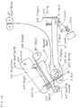
pre-feeder unit 4 in accordance with the invention will now be explained with reference to Figs. 23 and 24. - The construction shown in Fig. 23 follows that of the example illustrated with reference to Fig. 21, with the exception that when the motor PM1 is rotated in the opposite direction (the direction shown by an arrow B), the
feed roller 41a is caused to stop rather than rotate in the opposite direction. According to the example shown in Fig. 21, when thefeed roller 41a is rotated in the opposite direction, thecontinuous paper 1 is cut, but the rest of thecontinuous paper 1 may be fed back in that moment. The instant embodiment is provided to avoid this. - More specifically, the axis of the
feed roller 41a is provided at its one end with atoothed pulley 410 through a one-way clutch 410a, as illustrated in Fig. 23. Consequently, it is when the motor PM1 is driven in the forward direction (or in the direction shown by an arrow A) that the one-way clutch 410a is so actuated that thefeed roller 41a can rotate in the forward direction (or in the direction A). In contrast, it is when the motor PM1 is driven in the opposite direction (or in the direction shown by an arrow B) that the one-way clutch 410a disengages thepulley 410, so that it can be kept idle, thereby keeping thefeed roller 41a from rotation. - When the motor PM1 is driven in the opposite direction (or in the direction B), the
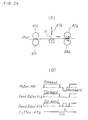
feed roller 42a is rotated in the feed direction, but thefeed roller 41a is not rotated by the rotational force of thepulley 410. Consequently, a sag in thecontinuous paper 1 is temporarily pulled, and so tension is imparted to thecontinuous paper 1. Subsequently, the continuous paper is fed by thefeed roller 42a under that tension, so that, as shown in the time chart presented in the form of Fig. 24(B), thecontinuous paper 1 can be cut along theperforation 17 by thecutter 47a at a timing at which that sag is pulled by thefeed roller 41a just after the backward driving of the motor PM1. - The
feed roller 41a is then not rotated, and so the feeding-back of the rest of thecontinuous paper 1 is avoided, thus enabling the distance to the next cutting position to be reduced. The time reduction achieved per ticket is slight, but the total ticketing time can be much reduced in the case of issuing a large number of tickets sequentially. - It will now be described how to regulate the position of the
MS unit 5 at which data recording is initiated. - As shown in Fig. 25(A), the main part of the
MS unit 5 is built up of a sensor SS for sensing the leading end of each ticket blank 1a, awrite head 50 disposed behind the sensor SS by a predetermined distance LI, aread head 51 located behind thewrite head 50 and a sensor ES located behind the readhead 51 for sensing the trailing end of each ticket blank 1a. - With each ticket blank 1a - that has been fed from the ticket blank holder 2a and is now ready to leave in the pre-feeder unit 4 - fed out of the
pre-feeder unit 4 as per ticketing instructions, it is fed by thebelt mechanism 52 to the passage for theMS unit 5. When the ticket blank 1a is carried to a given position through a predetermined distance S after its leading end has been sensed by the sensor SS, as shown in Fig. 25(B), boarding reservation data (departure date and time, flight number, passenger's name, and so on) sent out of external equipment is magnetically recorded by thewrite head 50 on themagnetic stripe 11 of the ticket blank 1a. - The data recorded on the
magnetic stripe 11 of the ticket blank 1a is reproduced by the readhead 51 for checkup. If there is no error, the ticket blank 1a is fed to theprinter unit 6 where the data is printed and then it is sent out of the issuance port. Then, when the print is ended, the completion of ticketing is notified. This enables the succeedingticket 1a to be ready to leave thepre-feeder unit 4. - It is here to be noted that the position of a predetermined distance S taken by the ticket blank 1a after its leading end has been detected lies at the position of a distance L2 from the leading end of the
magnetic stripe 11 to the write head 50 (i.e., L2=S-L1), and this distance L2 must lie within a certain tolerable range with respect to a predetermined size. - In other words, the writing of the data onto the magnetic stripe by the
write head 50 is initiated after the lapse of a time period t from the detection of the leading end of theticket 1a by the sensor SS to the time at which the leading end of the ticket blank 1a would reach the position of the distance S. - When the distance L2 is too short, reading is unlikely to occur because some difficulty is involved in the synchronization of the read signals, whereas when it is too long, some data are unlikely to be recorded because the recording zone of the
magnetic stripe 11 becomes narrow. For assuring stable reading and recording region, there are thus the ISO and JIS standards (e.g., 7.44 mm±1.0 mm). - However, the given distance S depends on the accuracy of the spacing between the sensor SS and the
write head 50 and, besides, there is an error in the accuracy of mechanical feeding by thebelt mechanism 52, which in turn gives rise to an error in the distance L2. For this reason, after data is actually recorded on the ticket blank 1a, the recording initiation position from the leading end of the magnetic strip of theticket 1a is measured to regulate the quantity of the error alone. So far, this regulation has been achieved by the following procedures. - The first procedure, as already mentioned above, involves recording data on the
magnetic stripe 11 of theticket 1a and visualizing the magnetic pattern with the use of a developer to measure the distance L2 to the write start position on the ticket blank 1a under a scaled magnifier. In the process of this development, themagnetic stripe 11 is treated with a developer composed of a mixture of a volatile liquid with magnetic powders. Then, the volatile component volatilizes, leaving the magnetic powders on the data part. - When the results of this measurement teach that the error deviates from the prescribed value, the relative distance between the sensor SS and the
write head 50 is adjusted as by changing the position at which the sensor SS is mounted, again, followed by magnetic recording and development to measure the recording start location. In other words, the first procedure is a sort of the method of trial and error. - The first procedure may be achieved by a mere displacement of the position of the sensor SS is mounted but, in this case, it is sometimes required to provide some mechanism for the fine adjustment of the location of the sensor SS.
- In the second procedure that is similar to the first procedure in that data is recorded on the
magnetic stripe 11 of the ticket blank 1a and then developed, the distance of movement of the ticket blank 1a from the time where the sensor SS detects the leading end of theticket 1a to the recording start time. - To be more specific, an encoder, not illustrated, is provided on the driving pulley of the
belt mechanism 52 for feeding theticket 1a. Then, the distance of movement of theticket 1a is calculated. It is when the sensor SS reaches a given calculated value t after detecting the leading end of the ticket blank 1a that thewrite head 50 starts to record. - This is followed by development and measurement. The recording start position, when there is an error, is regulated by increasing or decreasing this calculated (or set) value.
- It is noted that the second procedure may also be achieved by using a stepping motor for driving the driving pulley in place of the encoder, but there is a need of increasing or decreasing the stepping number of the motor.
- A problem with the above-mentioned conventional procedures, however, is that they are all time- and labor consuming, because of involving the steps of development, measurement and regulation after the recording of data on the magnetic stripe of a ticket blank.
- According to the instant example, this problem is solved by making it possible to regulate automatically the recording start position on a ticket blank by the mere insertion of the ticket blank.
- Fig. 26 is a block diagram presented for achieving this. In Fig. 26, a
control panel 26 is similar to that shown in Figs. 4 and 5, and includes a correction-mode indicating button 260 for setting the mode for determining a correction value for the recording start position on aticket 1a. Aclock generator 75 generates a clock signal of a frequency F. - A
clock counter 76, when the correction-mode indicating button 260 is pushed down, is actuated to count the number of all clock signals M sent out of theclock generator 75 from the time a sensor SS detects the leading end of the ticket la to the time the sensor SS detects the trailing end of theticket 1a. Fig. 29(b) represents the timings of the sensor-detected signal and the clock signals, and counts the time during which theticket 1a of accurate size passes by the sensor SS by the clock signals of frequency F. This is to measure the feed speed accurately. - A
RAM 77 stores the value of the frequency F of the clock signals sent out of theclock generator 75 and a recording frequency F of data "0" generated from a data-generator block 71 at a correction mode to be described later. A data-reception block 78 receives the data to be recorded, which is sent out of an external device. - A
main control block 70 includes a CPU and a control program memory, and the CPU controls each block according to the control program in the memory, feeding a ticket blank 1a, making a given record on themagnetic stripe 11 of the ticket blank 1a, reproducing the record for checkup, and printing data on the ticket blank 1a for ejection. - Further, the CPU, when the correction-mode-indicating button 260 is pushed down, is actuated to detect an error in the recording start position by a series of controls shown in Fig. 27, and thereby execute the automatic correction of the recording start position.
-
Reference numeral 72 stands for a motor driver that drives a motor M upon receipt of instructions fromCPU 70 to drive feedingbelts Reference numeral 73 denotes a sensor amplifier that amplifies the output of the sensor SS for output toCPU reproduction head 51 for output toCPU 70. - Fig. 27 represents the functions of
CPU 70 of Fig. 26 in a blocked form, and the functions of thecontrol block 70 will now be explained with reference thereto. - In Fig. 27, a cycle counter block 70-1 is constructed from a
peak detector sub-block 80, a cycle detector sub-block 81 and acounter 82, and a calculator block 70-2 is built up of a feedspeed calculator sub-block 83, a recording density calculator sub-block 84, a recording startposition calculator sub-block 85 and a correctiontime calculator sub-block 88. In what follows, the function of each block will be explained. - A feed
time setting block 92 is made up of a memory, and initially set there is a theoretical write start time t until the leading end of a ticket blank 1a is detected to start recording data, wherein t = Distance S to the recording start position to be described later/Feed Speed V. However, this preset t, when the correction time Δt to be described later is found, is replaced by a correction time t'(=t+Δt). - A block 71 (see Fig. 26) for generating data at the correction-mode time stores data "0" and "1" and, when the correction mode is indicated by pushing down the correction-mode-indicating button 260, is actuated to generate the data "0" that is recorded from the time the sensor SS detects the leading end of a ticket blank 1a to the time the data-recording start time (i.e., the feeding time t of the ticket blank 1a) and the data "1" that is recorded from the data-recording start time. Fig. 29(a) represents the timings of the sensor-detected signals and the recording signals. It is noted that the magnetic inversion cycles of the data "0" and "1" lie at a ratio of 2 to 1, and that the magnetic inversion cycle of the data "0" or the recording frequency is f.
- In the cycle counter block 70-1, the peak of the output signal corresponding to the magnetic inversion of the data read on the read
head 51 is detected by thepeak detector sub-block 80 from the leading end of the ticket blank 1a having the data "0" and "1" recorded thereon, as shown in Fig. 29(c)(1), and the number of all cycles N until the changing of the data from "0" to "1" is detected is counted by thecounter 82, as shown in Figs. 29(c)(2) and 29 (c)(3). - In other words, the
counter 82 counts the changing cycle of the data from "0" to "1" in terms of the number of all cycles detected by the cycle detector sub-block 81. Fig. 29(c)(4) represents a signal detecting that the peak signal cycle is reduced because of the changing of the data from "0" to "1". - In the feed
speed calculator sub-block 83, an actual feed speed V given by LF/M is found, wherein F is the clock frequency read fromRAM 77, M is all the clock signals counted by the clock counter and L is the length of the ticket blank 1a. - In the recording density calculator sub-block 84, a recording density given by f/V is found, wherein f is the recording frequency read from
RAM 77 and V is the actual feed speed. - The recording start
position calculator block 85 is built up of adistance calculator 86 and acomparator 87. In thedistance calculator 86, a distance S from the sensor SS to the recording start position given by NV/F is found, wherein N is the total cycle number N counted by the cycle calculator block 70-1 and f/V is the recording density calculated by the recording density calculator sub-block 84. In thecomparator 87, the absolute value Δs of a difference between the measured distance S and a preset distance S0 to the recording start position is found and compared with a prescribed value SL for an allowable tolerance limit set in an allowable-value setting block 91 to make determination of whether ΔS>SL or ΔS≤SL. When ΔS>S1, themain control block 71 is notified of the "need" of correcting the recording start position, and when ΔS≤SL, themain control block 71 is notified of the "no need" of correcting the recording start position. - The correction
time calculator block 88 includes acorrection data calculator 89 and a correctionfeed time calculator 90, and thecorrection data calculator 89, when there is the "need" of correcting the recording start position, calculates the correction time Δt given by ΔS/V, where ΔS is the difference found by thecomparator 87 and V is the feed speed, according to instructions from themain control block 71. With the correction time Δt found, the correction time feedtime calculator block 90 is actuated to correct the feed (write start) time t that is initially set in the feedtime setting block 92 with the correction time Δt. That is, the correction feed time t'=t±Δt is calculated. - In the ensuing description, the operation of the instant example will be explained with reference to the flow chart of Fig. 28.
- (1) First, the power source of the apparatus is put on and the correction-mode-indicating button 260 is pressed down to set the correction mode.
Then, a ticket blank 1a (of accurate length L) for testing purposes is inserted through the insertingport 21, shown in Figs. 4 and 5, whence it is fed through theMS unit 5 to the unit 5c where the manually inserted ticket blank stands for further feeding, as is the case with the cut ticket blank. From this unit 5c, it is fed to the MS read-write unit 5a. When the leading end of the ticket blank 1a is here detected by the sensor SS, theclock counter 76 is triggered to count the number of all clock signals (of frequency F) generated until the sensor SS detects the trailing end of the ticket blank 1a. Then, the accurate actual feed speed V is found in the feedspeed calculator block 83 from the length L of the ticket blank 1a and the total clock signals M; in other words, it is calculated from V=L x F/M. - (2) Further, the recording density f/V is found in the recording density calculator block 84 by dividing the recording frequency f read from
RAM 77 by the feed speed V. - (3) From the time the sensor SS detects the leading end of the ticket blank 1a, on the other hand, recording is made with the use of the feed (write start) time t initially set in the feed
time setting block 92. Before the recording start time t, themain control block 70 outputs continuously the data "0" from adata generation unit 71 that works at the correction value-determining time for recording them on themagnetic stripe 11 of the ticket blank 1a by thewrite head 50. After the recording start time t, the data is changed to "1" for recording. - (4) Now, the data "0" is read by the read
head 51 from the leading end of the fed ticket blank 1a, and the counter 82 counts the total cycle number N until the cycle detector sub-block 81 detects that the data is changed from "0" to "1". - (5) The counted total cycle number N and the recording density f/V calculated at Step (2) are fed to the recording start
position calculator block 85, where the distance S to the recording start position is found by thedistance calculator 86; in other words, the distance is calculated from S=N x V/f. - (6) In the
comparator 87, the absolute value ΔS (=S-S0) of the difference between the distance S and the preset distance S0 to the recording start position is found and compared with the prescribed value SL in the allowablevalue setting block 91 to provide determination of ΔS>SL or ΔS≤SL, notifying themain control block 71 of the "need" or "no need" of correcting the distance S. When there is no need, no correction occurs. Hence, subsequent-recording of the ticket blanks 1A is done with the use of the write start time t that is initially set in the feedtime setting unit 12. - (7) When there is the "need" of correcting the distance S, ΔS is divided by the feed speed V - that is found by in the feed speed calculator block 83 - by the
correction data calculator 89 in the correctiontime calculator block 88 to find the correction time Δt (=ΔS/V). - (8) Then, the intially set recording start time t is read form the feed
time setting block 92, and the correction feed time t'=t+Δt is found in the correctionfeed time calculator 90 by the correction time Δt. The correction feed time t" is then renewed in the feedtime setting block 92 in place of the initially set feed time t. - (9) After that, the ticket blank la is fed to the
printer unit 6 where the correction value (i.e., ΔS) is printed for issuance through an issuance port. This enables the operator to confirm the quantity of regulation. Finally, the correction-mode-indicating button 260 is again pressed down to release the correction mode, making the correction of the recording start position complete. - After the passing of the time t' from the time the sensor SS detects the leading end of the ticket blank 1a, the
write head 50 starts to write the data with the use of the thus corrected write start time (feed time) t', whereby the data is written onto the ticket blank la from the position away from the leading end by the given distance L1. Such correction is usually done when hardware is forwarded from plants or in-situ replacement of the whole or a part of theMS unit 5. - Therefore, the instant example can dispense with some post-data-recording steps of development, measurement and regulation that are required for conventional correction procedures, and so can eliminate troublesome development and measurement works and works for regulating the distances of the sensor SS and write
head 50 for correcting the recording start position on the ticket blank 1a. - While the instant embodiment has been described as making correction only when the difference ΔS, when found, exceeds the allowable value SL, it is understood that only the feed time Δt corresponding to the difference ΔS may be corrected irrespective of the allowable value SL.
Claims (8)
- A ticket printer for magnetically recording and printing ticketing data on ticket blanks for issuance, including:ticket blank holder means (3a,3b) for holding a continuous form of medium having perforations that can be separated along the perforations into individual ticket blanks;magnetic recording means (5) for magnetically recording ticket data on a magnetic layer of the individual ticket blanks;printing means (6) for printing ticket data on each ticket blank for issuance; andpre-feeder means (4) for feeding the continuous medium from the ticket blank holder means, cutting the continuous medium along the perforation into the said individual ticket blanks and feeding these individual ticket blanks to the magnetic recording means, the pre-feeder means including:feed rollers (41,42) for feeding the continuous medium and the individual ticket blanks; and a cutter (47a) provided between the feed rollers, for cutting the continuous medium as aforesaid;in which the pre-feeder means further includes driving means for forwardly driving both feed rollers (41,42) when said continuous medium is to be fed;characterised in that the driving means is further adapted to hold the first feed roller (41) in the feed path and forwardly drive the second feed roller (42) in the feed path when the continuous medium is to be cut, thereby applying tension to the medium on both sides of the perforation.
- A ticket printer as recited in claim 1, wherein the pre-feeder means (4), after feeding the continuous form of medium and cutting it along the perforations into individual ticket blanks, enables the blanks to stand ready for further feeding.
- A ticket printer as recited in claims 1 or 2, wherein the ticket blank holder means (3a,3b) is located in a lower portion of the apparatus body and the magnetic recording (5) and printing (6) means are located in an upper portion of the apparatus body, so that the ticket blanks can be fed by the pre-feeder means (4) from the ticket blank holder means (3a,3b) to the rear of the magnetic recording means (5) in the upper portion of the apparatus body.
- A ticket printer as recited in any of claims 1 to 3, in which the pre-feeder means (4) is designed to feed the continuous form of medium until a perforation in the medium is located at a cutter position, and then to cut the medium by a cutter (47a,47b).
- A ticket printer as recited in any of claims 1 to 4, wherein the pre-feeder means (4) is provided with a biasing mechanism (49) for biasing the ticket blanks to one side.
- A ticket printer as recited in any of claims 1 to 5, wherein the magnetic recording means (5) includes a biasing mechanism that, during feeding of the cut ticket blanks by a belt, biases the fed ticket blanks to one side.
- A ticket printer as recited in any of claims 1 to 6, wherein the printing means (6) includes a printing mechanism (60) for positioning the leading ends of the magnetically recorded ticket blanks and then printing the ticket blanks.
- A ticket printer as recited in any preceding claim, in which the printing means is a thermal printer.
Applications Claiming Priority (10)
| Application Number | Priority Date | Filing Date | Title |
|---|---|---|---|
| JP25613/92 | 1992-02-13 | ||
| JP4025613A JP2570047B2 (en) | 1992-02-13 | 1992-02-13 | Tension applying mechanism |
| JP12192692A JP2786371B2 (en) | 1992-05-14 | 1992-05-14 | Thermal head support structure |
| JP12192892A JPH05314333A (en) | 1992-05-14 | 1992-05-14 | Ticket issuing machine |
| JP121927/92 | 1992-05-14 | ||
| JP121928/92 | 1992-05-14 | ||
| JP4121927A JP3012735B2 (en) | 1992-05-14 | 1992-05-14 | Ticket issuing machine |
| JP121926/92 | 1992-05-14 | ||
| JP4309130A JP2906880B2 (en) | 1992-11-19 | 1992-11-19 | Automatic correction method of recording start position of recording medium and medium recording apparatus |
| JP309130/92 | 1992-11-19 |
Publications (3)
| Publication Number | Publication Date |
|---|---|
| EP0556071A2 EP0556071A2 (en) | 1993-08-18 |
| EP0556071A3 EP0556071A3 (en) | 1993-12-29 |
| EP0556071B1 true EP0556071B1 (en) | 1997-09-17 |
Family
ID=27520754
Family Applications (1)
| Application Number | Title | Priority Date | Filing Date |
|---|---|---|---|
| EP93301067A Expired - Lifetime EP0556071B1 (en) | 1992-02-13 | 1993-02-15 | Ticket printer |
Country Status (3)
| Country | Link |
|---|---|
| US (1) | US6338436B1 (en) |
| EP (1) | EP0556071B1 (en) |
| DE (1) | DE69313889T2 (en) |
Families Citing this family (13)
| Publication number | Priority date | Publication date | Assignee | Title |
|---|---|---|---|---|
| ZA929840B (en) * | 1991-12-19 | 1993-06-23 | Telkor Pty Ltd | Ticket issuing device. |
| DE69313889T2 (en) | 1992-02-13 | 1998-01-15 | Fujitsu Ltd | Ticket printer |
| WO2000079488A1 (en) * | 1999-06-17 | 2000-12-28 | Thales E-Transactions S.A. | Ticket printing device, in particular transport tickets, of different formats |
| DE10039699C2 (en) * | 2000-08-14 | 2003-12-04 | Wincor Nixdorf Int Gmbh | Device for processing betting slips |
| JP3664644B2 (en) * | 2000-10-06 | 2005-06-29 | 日立オムロンターミナルソリューションズ株式会社 | Magnetic head support structure and magnetic card reader |
| JP4575032B2 (en) * | 2004-05-31 | 2010-11-04 | 富士通株式会社 | Medium processing apparatus and medium issuing apparatus using the same |
| US7059794B2 (en) * | 2004-06-28 | 2006-06-13 | Transact Technologies Incorporated | Methods and apparatus for bursting perforated paper stock |
| US8164775B2 (en) * | 2006-09-26 | 2012-04-24 | Intermec Ip Corp. | Apparatus and method for automated ticket and boarding |
| DE102008018597A1 (en) * | 2008-04-11 | 2009-10-15 | Daniel Bossert | Method for controlling a workflow |
| WO2012057961A2 (en) | 2010-10-27 | 2012-05-03 | Kraft Foods Global Brands Llc | Magnetically closable product accommodating package |
| DE102012001121C5 (en) * | 2012-01-23 | 2018-01-04 | Leonhard Kurz Stiftung & Co. Kg | Security document, method for producing a security document and method for producing an individualized security document |
| GB2515993B (en) * | 2013-04-08 | 2016-04-27 | Innovative Tech Ltd | A banknote and voucher handling apparatus |
| JP7073971B2 (en) * | 2018-08-02 | 2022-05-24 | セイコーエプソン株式会社 | Printing equipment |
Family Cites Families (23)
| Publication number | Priority date | Publication date | Assignee | Title |
|---|---|---|---|---|
| GB1333161A (en) * | 1970-01-30 | 1973-10-10 | Windmoeller & Hoelscher | Severing apparatus for severing lengths of tube from flattened scored tubing |
| JPS50992Y1 (en) * | 1970-02-27 | 1975-01-11 | ||
| US3902954A (en) * | 1971-11-12 | 1975-09-02 | Fmc Corp | Apparatus for making bottom seal thermoplastic bags |
| CA974164A (en) * | 1972-05-30 | 1975-09-09 | Standard Register Company (The) | Burster apparatus |
| JPS5556949A (en) | 1978-10-25 | 1980-04-26 | Nippon Koku Kk | Continuous sheet feeder |
| DE2937312A1 (en) * | 1979-09-14 | 1981-03-26 | Rena Büromaschinenfabrik GmbH & Co, 82041 Deisenhofen | Machine for transverse slitting of computer print out - is arranged vertically to minimise space requirement |
| JPS57144793A (en) * | 1981-03-05 | 1982-09-07 | Ricoh Co Ltd | Heatsensitive recording material |
| US4637286A (en) * | 1984-07-24 | 1987-01-20 | Allied Corporation | Staple cutting for fiber reinforcement material |
| US4670636A (en) * | 1984-09-19 | 1987-06-02 | General Electric Company | Heat assisted parting of amorphous alloys |
| EP0184132B1 (en) * | 1984-11-30 | 1990-04-11 | Fuji Photo Film Co., Ltd. | Thermal recording apparatus |
| US4691605A (en) * | 1985-07-22 | 1987-09-08 | Sanders Associates, Inc. | Cutter assembly with rotating knife blade |
| US4895466A (en) * | 1988-01-20 | 1990-01-23 | Datamax Corporation | Processor for forms with multi-format data |
| FR2628084B1 (en) * | 1988-01-22 | 1991-08-30 | Dassault Electronique | DEVICE FOR PROCESSING TITLES, IN PARTICULAR AIR TRANSPORT TITLES COMPRISING MAGNETIC INFORMATION |
| JP2731164B2 (en) * | 1988-06-02 | 1998-03-25 | 株式会社東芝 | Automatic ticket gate system |
| US5229586A (en) * | 1988-10-28 | 1993-07-20 | Tokyo Electric Co., Ltd. | Card issuing apparatus having sequential processing units |
| IT215262Z2 (en) * | 1988-11-21 | 1990-09-11 | Meschi Ind Grafica | STRAPPERINA FOR TAPES OF MATERIALS IN SHEETS SUCH AS PAPER TAPES. |
| US4928133A (en) * | 1989-02-03 | 1990-05-22 | Sci Systems, Inc. | Printer and method |
| US5206489A (en) * | 1989-02-17 | 1993-04-27 | Datacard Corporation | Magnetic encoding device for cards |
| JP2901075B2 (en) * | 1989-04-26 | 1999-06-02 | 共同印刷株式会社 | Magnetic card |
| US5133615A (en) * | 1989-09-07 | 1992-07-28 | Tokyo Electric Co., Ltd. | Ticket issuing machine |
| US5268561A (en) * | 1990-08-28 | 1993-12-07 | Oki Electric Industry Co. Ltd. | Ticket issuing apparatus |
| DE69313889T2 (en) | 1992-02-13 | 1998-01-15 | Fujitsu Ltd | Ticket printer |
| US5309176A (en) * | 1992-08-25 | 1994-05-03 | Sci Systems, Inc. | Airline ticket printer with stepper motor for selectively engaging print head and platen |
-
1993
- 1993-02-15 DE DE69313889T patent/DE69313889T2/en not_active Expired - Fee Related
- 1993-02-15 EP EP93301067A patent/EP0556071B1/en not_active Expired - Lifetime
-
1995
- 1995-04-14 US US08/422,770 patent/US6338436B1/en not_active Expired - Fee Related
Also Published As
| Publication number | Publication date |
|---|---|
| DE69313889D1 (en) | 1997-10-23 |
| EP0556071A3 (en) | 1993-12-29 |
| DE69313889T2 (en) | 1998-01-15 |
| EP0556071A2 (en) | 1993-08-18 |
| US6338436B1 (en) | 2002-01-15 |
Similar Documents
| Publication | Publication Date | Title |
|---|---|---|
| US5122967A (en) | Postage stamp and dispensing system therefor | |
| US4924240A (en) | Feed for thermal printing ribbon | |
| US7637678B2 (en) | System and method for determining the status of a label in a roll of label stock | |
| US6338436B1 (en) | Variable ticket and ticket printer | |
| US4679953A (en) | Paper feeding and ejecting device for a printing apparatus | |
| US6350005B1 (en) | Method and apparatus for processing recording media having embedded information | |
| US4895466A (en) | Processor for forms with multi-format data | |
| US5529414A (en) | Paper feeding apparatus for printer | |
| US6846118B2 (en) | Printing system, printing method, and recording medium | |
| US4899172A (en) | Method and apparatus for perforating indicia on used thermal transfer ribbon within a cassette | |
| JP3012735B2 (en) | Ticket issuing machine | |
| JP2571848B2 (en) | Printing device for printed photos | |
| JPH054227B2 (en) | ||
| JPS6145572Y2 (en) | ||
| JPH05314333A (en) | Ticket issuing machine | |
| JPH1035039A (en) | Ticket issuing device | |
| JPH08320952A (en) | Recording medium processing device | |
| HK1092577B (en) | System and method for determining the status of a label in a roll of label stock | |
| HK1139495A (en) | System and method for determining the status of a label in a roll of label stock | |
| JPH0512519A (en) | Magnetic medium ticket issuing control method and magnetic medium ticket issuing device | |
| JPH07272018A (en) | Recording medium position detecting device and recording medium position detecting method | |
| JPH09226222A (en) | Image forming device | |
| JPS6147335A (en) | Label-feed controller for lebel printer |
Legal Events
| Date | Code | Title | Description |
|---|---|---|---|
| PUAI | Public reference made under article 153(3) epc to a published international application that has entered the european phase |
Free format text: ORIGINAL CODE: 0009012 |
|
| AK | Designated contracting states |
Kind code of ref document: A2 Designated state(s): DE FR GB |
|
| PUAL | Search report despatched |
Free format text: ORIGINAL CODE: 0009013 |
|
| AK | Designated contracting states |
Kind code of ref document: A3 Designated state(s): DE FR GB |
|
| 17P | Request for examination filed |
Effective date: 19940623 |
|
| 17Q | First examination report despatched |
Effective date: 19951020 |
|
| GRAG | Despatch of communication of intention to grant |
Free format text: ORIGINAL CODE: EPIDOS AGRA |
|
| GRAH | Despatch of communication of intention to grant a patent |
Free format text: ORIGINAL CODE: EPIDOS IGRA |
|
| GRAH | Despatch of communication of intention to grant a patent |
Free format text: ORIGINAL CODE: EPIDOS IGRA |
|
| GRAA | (expected) grant |
Free format text: ORIGINAL CODE: 0009210 |
|
| AK | Designated contracting states |
Kind code of ref document: B1 Designated state(s): DE FR GB |
|
| REF | Corresponds to: |
Ref document number: 69313889 Country of ref document: DE Date of ref document: 19971023 |
|
| ET | Fr: translation filed | ||
| PLBE | No opposition filed within time limit |
Free format text: ORIGINAL CODE: 0009261 |
|
| STAA | Information on the status of an ep patent application or granted ep patent |
Free format text: STATUS: NO OPPOSITION FILED WITHIN TIME LIMIT |
|
| 26N | No opposition filed | ||
| REG | Reference to a national code |
Ref country code: GB Ref legal event code: IF02 |
|
| PGFP | Annual fee paid to national office [announced via postgrant information from national office to epo] |
Ref country code: DE Payment date: 20090213 Year of fee payment: 17 |
|
| PGFP | Annual fee paid to national office [announced via postgrant information from national office to epo] |
Ref country code: GB Payment date: 20090211 Year of fee payment: 17 |
|
| PGFP | Annual fee paid to national office [announced via postgrant information from national office to epo] |
Ref country code: FR Payment date: 20090213 Year of fee payment: 17 |
|
| GBPC | Gb: european patent ceased through non-payment of renewal fee |
Effective date: 20100215 |
|
| REG | Reference to a national code |
Ref country code: FR Ref legal event code: ST Effective date: 20101029 |
|
| PG25 | Lapsed in a contracting state [announced via postgrant information from national office to epo] |
Ref country code: FR Free format text: LAPSE BECAUSE OF NON-PAYMENT OF DUE FEES Effective date: 20100301 |
|
| PG25 | Lapsed in a contracting state [announced via postgrant information from national office to epo] |
Ref country code: DE Free format text: LAPSE BECAUSE OF NON-PAYMENT OF DUE FEES Effective date: 20100901 |
|
| PG25 | Lapsed in a contracting state [announced via postgrant information from national office to epo] |
Ref country code: GB Free format text: LAPSE BECAUSE OF NON-PAYMENT OF DUE FEES Effective date: 20100215 |