EP0555094A2 - Beam landing correction apparatus for a cathode ray tube - Google Patents
Beam landing correction apparatus for a cathode ray tube Download PDFInfo
- Publication number
- EP0555094A2 EP0555094A2 EP93300876A EP93300876A EP0555094A2 EP 0555094 A2 EP0555094 A2 EP 0555094A2 EP 93300876 A EP93300876 A EP 93300876A EP 93300876 A EP93300876 A EP 93300876A EP 0555094 A2 EP0555094 A2 EP 0555094A2
- Authority
- EP
- European Patent Office
- Prior art keywords
- correction
- landing
- magnetic field
- mislanding
- landing correction
- Prior art date
- Legal status (The legal status is an assumption and is not a legal conclusion. Google has not performed a legal analysis and makes no representation as to the accuracy of the status listed.)
- Withdrawn
Links
Images


Classifications
-
- H—ELECTRICITY
- H01—ELECTRIC ELEMENTS
- H01J—ELECTRIC DISCHARGE TUBES OR DISCHARGE LAMPS
- H01J29/00—Details of cathode-ray tubes or of electron-beam tubes of the types covered by group H01J31/00
- H01J29/003—Arrangements for eliminating unwanted electromagnetic effects, e.g. demagnetisation arrangements, shielding coils
-
- H—ELECTRICITY
- H04—ELECTRIC COMMUNICATION TECHNIQUE
- H04N—PICTORIAL COMMUNICATION, e.g. TELEVISION
- H04N9/00—Details of colour television systems
- H04N9/12—Picture reproducers
- H04N9/16—Picture reproducers using cathode ray tubes
- H04N9/29—Picture reproducers using cathode ray tubes using demagnetisation or compensation of external magnetic fields
-
- H—ELECTRICITY
- H01—ELECTRIC ELEMENTS
- H01J—ELECTRIC DISCHARGE TUBES OR DISCHARGE LAMPS
- H01J2229/00—Details of cathode ray tubes or electron beam tubes
- H01J2229/0007—Elimination of unwanted or stray electromagnetic effects
- H01J2229/003—Preventing or cancelling fields entering the enclosure
- H01J2229/0038—Active means
Definitions
- the present invention relates to a landing correction apparatus for preventing a possible degradation of chromatic purity caused by an influence of a geomagnetism in a color television receiver.
- a landing position of an electron beam is varied by an influence of a geomagnetism to result in a change in luminance and chromaticity of the image picture displayed on the display screen.
- a cathode ray tube for use in a high vision system where high density phosphor elements having a fine pitch is adopted, there occurs a greater degree of a landing error of an electron beam (referred to as “mislanding" hereinafter) due to the influence of the geomagnetism.
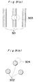
- the degree of electron beam mislanding depends on the arrangement of the phosphor elements.
- the stripe type arrangement has a greater tolerance for the beam landing because no substantial change takes place in luminance efficiency of the phosphor element when the beam landing position varies in the lengthwise direction of the stripe phosphor element.
- reference numerals 301 and 302 denote phosphor elements
- reference numerals 303 and 304 depicted by broken lines denote mislanding positions of electron beams.
- the mislanding of electron beams is corrected using a landing correction coil through which an appropriate electric current is flowed for canceling the influence of the geomagnetism.
- a conventional electron beam landing correction apparatus there has been employed, for example, a beam landing correction apparatus for a color cathode ray tube as disclosed in the Japanese Patent (Unexamined) Laid-Open Publication No. HEI 2-29187.
- the apparatus comprises a cathode ray tube (CRT) 101 having a display panel 101a, a deflection yoke 102, periphery landing correction coils C1 through C6 for correcting the mislanding of electron beams in peripheral portions of the screen, photosensors Ps1 through Ps6 for detecting the mislanding, a gun center coil 107 for correcting the mislanding of the electron beams at the center portion of the screen, and a measurement coil 108 for generating an auxiliary deflection magnetic field for measuring the mislanding amount.
- CTR cathode ray tube
- the apparatus further comprises a sample/hold circuit (S/H) 109 for sampling and holding an output of each photosensor, a multiplexer 110, an analog-to-digital (A/D) converter 111, a digital calculation circuit 112, a measurement control circuit 113, a demultiplexer 114, a latch 115, a digital-to-analog (D/A) converter 116, a drive circuit 117 for driving the landing correction coils, and a video circuit 118 for processing a video signal.
- S/H sample/hold circuit
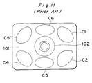
- Fig. 11 shows an arrangement of the periphery landing correction coils C1 through C6 for correcting the mislanding of the electron beams at the peripheral portions of the screen.
- Figs. 12 (a) and 12 (b) show an arrangement of photosensors Ps1 through Ps6 for detecting the luminance on the screen.
- the positions of the photosensors Ps1 through Ps6 corresponds to the positions of the landing correction coils C1 through C6 at the peripheral portions of the screen.
- the photosensors are covered by a frame member 137.
- a phosphor element 139 is provided on the inner surface of the display panel 101a at the face plate of the cathode ray tube 101.
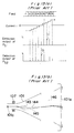
- Figs. 13 (a) and 13 (b) are charts for explaining a mislanding detection operation, while Fig. 14 shows a relationship between the beam landing position and the light quantity detected by a photosensor.
- a measurement current i which is applied to the mislanding amount measurement coil 108 from the measurement control circuit 113, the current i increases in steps from a negative potential region to a positive potential region for measuring the mislanding amount in each field as shown in Fig. 13 (a).
- a control signal e is supplied from the measurement control circuit 113 to the video circuit 118 so that the video circuit 118 provides, for example, a video signal for generating a green or white raster to the cathode 101c of the cathode ray tube 101.
- the deflection center in the deflection yoke position is changed as indicated by the beam loci in Fig. 13 (b). That is, the beam is applied to the position on the screen from a cathode 101c passing through an aperture mask 146 and the beam landing position is moved in the horizontal direction of the screen as indicated by arrows in Fig. 13 (b) (vertical direction in the figure).
- Reference numeral 143 denotes a center beam when no deflection is applied
- numeral 144 denotes an electron beam deflected by the geomagnetism
- numeral 145 denotes a mislanding-corrected beam deflected by the gun center coil 107.
- Light quantity detection outputs of the photosensors Ps1 through Ps6 are sampled every field in the sample/hold circuit 109 as shown in Fig. 13 (a), and the sampled data is transmitted via the multiplexer 110 to the analog-to-digital converter 111 and then supplied to the digital calculation circuit 112 in a form of a digital signal.
- the detected light quantity output of the phosphors takes its maximum value at the optimum landing position and gradually decrease as it departs from the optimum landing position as shown in Fig. 14. Since the mislanding amount differs in different portions of the screen, the optimum field number at which the maximum light quantity can be obtained differs in each photosensor.
- the digital calculation circuit 112 calculates measurement currents i1, i2, ..., i6 corresponding to the position of each of the photosensors Ps1 through Ps6 at which the maximum output is obtained. Furthermore, an average or a weighted average of the current values are calculated to obtain a correction current d0 to be applied to the gun center coil 107.
- the correction current d0 is a direct current which is used for the landing correction in a center area of the screen.
- correction currents d1, d2, ..., d6 are calculated from the measurement currents i1, i2, ..., i6.
- the correction currents d1, d2, ..., d6 calculated in the calculation circuit 112 are each output via the demultiplexer 114 to the latch circuit 115 and further converted into an analog form by means of the digital-to-analog (D/A) converter 116 to be subsequently supplied via the drive circuit 117 to each of the periphery landing correction coils C1 through C6.
- D/A digital-to-analog
- correction currents d1, d2, ..., d6 are direct currents to be supplied to the correction coils at the peripheral portions of the cathode ray tube to correct the beam mislanding which cannot be removed by the gun center coil 107.
- the optimum landing position is specified to the point at which the light quantity detected by the photosensor is at its maximum value without taking any matter of chromaticity into consideration, and therefore there also arises another problem that no sufficient uniformity in chromaticity can be achieved in the displayed picture even when a landing correction is effected.
- the present invention provides a beam landing correction apparatus which is capable of correcting with high accuracy the influence of the geomagnetism which extends irregularly in a cathode ray tube and which has a higher intensity in the peripheral portions of the cathode ray tube.
- the present invention provides a beam landing correction apparatus capable of effecting a quantitative landing correction with high accuracy in a short time by detecting chromaticity data and luminance data on the screen to obtain a beam mislanding amount and to generate a correction current corresponding to the mislanding amount to achieve an automatic correction operation.
- the present invention provides a beam landing correction apparatus capable of uniformizing the chromaticity and luminance on the screen by detecting the chromaticity data as well as luminance data of a display image of a video signal on the display screen, obtaining a mislanding amount according to the detected chromaticity and luminance data, and supplying a correction current corresponding to the mislanding amount to the afore-mentioned landing correction coils to effect an automatic landing correction.
- the beam landing correction apparatus of the first embodiment comprises a plurality of landing correction coils arranged on peripheral portions of a cathode ray tube (CRT), where the landing correction coils consist of x-axis direction correction coils 1 through 4 for correcting mislanding in the x-axis direction and y-axis direction correction coils 5 through 8 for correcting mislanding in the y-axis direction.
- CRT cathode ray tube
- the landing correction coils 1 through 8 are arranged by pairing each of the x-axis direction correction coils 1 through 4 with each of the y-axis direction correction coils 5 through 8 at four peripheral corner portions of the cathode ray tube because large mislanding of electron beams is caused due to a concentration of the geomagnetism at the peripheral portions of the cathode ray tube by an influence of a frame member and the like supporting the cathode ray tube.
- the x-axis direction correction coils and the y-axis direction correction coils are arranged at peripheral portions of the cathode ray tube in such a manner that the magnetic fields generated by the x-axis direction correction coils and the magnetic fields generated by the y-axis direction correction coils cross each other at right angles.
- the apparatus further comprises a static landing correction coil 9 for correcting static mislanding of electron beams, which is arranged at a neck portion of the cathode ray tube.
- the apparatus is further comprised of a drive section 10 for supplying an electric correction signal to each of the landing correction coils 1 through 9, a control section 11 for controlling the drive section 10 to generate an appropriate correction signal to be supplied to the drive section 10 so as to cancel the influence of the geomagnetism, and a display section 12 for supplying a video signal to the cathode ray tube to display an image of the video signal on a screen of the cathode ray tube.
- the mislanding of beams can be corrected with high accuracy using the resultant correction magnetic field combination of the x-axis component and y-axis component of the correction magnetic field.
- a pair of the x-axis direction correction coil 1 and the y-axis direction correction coil 6 serve as a landing correction coil pair for correcting the beam mislanding in the upper right portion of the screen of the cathode ray tube in the figure.
- Figs. 2 (a) and 2 (b) show the influence of the geomagnetism exerted on the electron beam movement.
- Figs. 2 (a) shows the influence of the geomagnetic field in different geographical directions East, West, South and North and
- Figs. 2 (b) shows the influence of the vertical magnetic fields exerted on the movement of an electron beam, where the electron beam on the screen receives different influence depending on the geographical direction and the northern or southern hemispheric condition.
- the influence of the geomagnetism exerted on the beam movement is an important factor in terms of color purity. Therefore, a uniform image can be displayed by performing landing corrections particularly at peripheral portions with landing correction coils arranged at the peripheral four corner portions of the screen to completely effect cancellation of the influence of the geomagnetism. It is noted here that the cancellation of the influence of the geomagnetism can be achieved by controlling the polarity and the quantity of a direct current potential to be supplied to the landing correction coils in each direction.
- reference numeral 40 denotes a geomagnetism vector causing a beam mislanding
- reference numeral 41 denotes an electron beam vector.
- the beam mislanding occurs for the reason that the Lorentz's force is exerted on the electron beam to displace the landing position of the electron beam in the cathode ray tube.
- the magnitude of the Lorentz's force causing the beam mislanding depends on the value of sin ⁇ .
- the Lorentz's force can be made zero when the geomagnetic direction and the electron beam direction coincide with each other.
- a high-accuracy correction can be achieved by varying the magnitude and direction of the correction magnetic field vector generated by the x-axis direction correction coil and the y-axis direction correction coil to vary the geomagnetic direction thereby making the geomagnetic direction coincide with the electron beam direction.
- peripheral landing correction coils 1 through 8 as in the present embodiment, it becomes possible to reduce a correlation on the display screen of a color television, i.e., it is possible to prevent a phenomenon that a correction effected at a portion increases a mislanding amount at another portion.
- the static correction coil 9 is provided at the neck portion of the cathode ray tube to permit a static correction of the beam mislanding.
- Figs. 3 (a) and 3 (b) show a modified example of the landing correction apparatus having the same construction as that of the first embodiment except employing a magnetic field detecting section (MFDS) and a geomagnetism direction setting section.
- the beam landing correction apparatus comprises partial landing correction coils 13 through 20, a static correction coil 21, a drive section 22 for supplying a correction current signal to the above-mentioned correction coils, in the same manner as that of the first embodiment.
- the apparatus further comprises a magnetic field detection section (MFDS) 23 for externally detecting the intensity and direction of the geomagnetism at various portions of the display screen, a control section 24 for controlling the drive section 22 by generating a control signal in response to receiving the geomagnetic field intensity and direction output from the magnetic field detection section 23, a display section 25 for displaying an image on the screen of the cathode ray tube, and a setting section 26 for manually setting the direction of the geomagnetism, thereby to achieve an automatic landing correction.
- MFDS magnetic field detection section
- the automatic landing correction of the landing correction apparatus is realized by providing the magnetic field detection section 23 for detecting the intensity and direction of the geomagnetism.
- the output of the magnetic field detection section (MFDS) 23 is transmitted to the control section 24 which generates a control signal according to the received detection values of the intensity and direction of the geomagnetism thereby to control the drive section 22 for supplying a correction current signal to each of the correction coils 13 through 20 and 21.
- correction data corresponding to the intensity and direction of the geomagnetism are already stored in the control section 24 as described in the first embodiment. It is also possible to manually set the direction of the geomagnetism by providing the setting section 26.
- partial landing correction coils 1 through 8 and 13 through 20 have rectangular shapes in the present embodiment, it is of course effective that they have other shapes.
- Fig. 4 (a) shows a beam landing correction apparatus in accordance with a second embodiment of the present invention
- Fig. 4 (b) shows an arrangement of the partial landing correction coils, which has a similar construction to that of the first embodiment except employing a mislanding error detection section (MEDS).
- the present apparatus comprises peripheral landing correction coils 27 through 34, a static correction coil 35, a drive section 36 for supplying a correction current to the above-mentioned correction coils in the same manner as that of the first embodiment.
- the apparatus further comprises a mislanding error detection section (MEDS) 37 for detecting the luminance and chromaticity on the screen of the color television display to detect a mislanding of an electron beam, a control section 38 for generating a control signal according to an output from the mislanding error detection section (MEDS) 37 to control the drive section 36, and a display section 39 for displaying an image on the screen of the cathode ray tube.
- a mislanding error detection section (MEDS) 37 for detecting the luminance and chromaticity on the screen of the color television display to detect a mislanding of an electron beam
- a control section 38 for generating a control signal according to an output from the mislanding error detection section (MEDS) 37 to control the drive section 36
- a display section 39 for displaying an image on the screen of the cathode ray tube.
- the following describes the operation of the landing correction apparatus of the second embodiment having the construction mentioned above.
- the mislanding error detection section (MEDS) 37 By arranging the mislanding error detection section (MEDS) 37 at a portion to be subjected to a landing correction, the luminance and chromaticity data at the portion to be corrected is taken in by means of a photoelectric transfer element PE to detect the beam mislanding according to the luminance and chromaticity data obtained.
- the mislanding error detected by the detection section (MEDS) 37 is transmitted to the control section 38, which generates a control signal according to the mislanding error data output from the detection section (MEDS) 37 to control the drive section 36 thereby to effect an automatical landing correction.
- control section 38 The following describes the operation of the control section 38 in detail. Although the amount of the mislanding error is evaluated based on the luminance and chromaticity data in the present embodiment, it is necessary to determine a convergence condition which is the decisive factor in the automatical landing correction.
- Y and r represent respectively an error in luminance and an error in chromaticity with respect to reference values
- Y1 represents the luminance at the correction point
- x and y represent the chromaticity values at the correction point
- Y0 represents the reference value in luminance
- x0 and y0 represent the reference values in chromaticity.
- the control section 38 By obtaining the mislanding error at the correction point according to the above equations, the control section 38 generates the control signal to control the drive section 36 which generates an electric correction current to be flowed through each of the landing correction coils 27 through 34 and 35 such that the mislanding evaluation amount at the correction point comes closer to the reference value.
- the convergence condition is determined while attaching great importance to the chromaticity, i.e., the value r in the above equation. This is because the chromaticity does not always come closest to the reference value at the point where the maximum luminance is achieved, and making much of the uniformity on the display screen in a color television receiver, the convergence condition should be determined putting more weight on the chromaticity.
- a concrete convergence condition is determined as follows. That is, the point at which the error in chromaticity r is in a specified permissive range and the maximum luminance is achieved in the same range is determined to be the convergence point.
- the value r i.e., a distance from the reference value is within 0.01 on the chromaticity diagram in determining the above-mentioned permissive range.
- the mislanding correction is performed by obtaining the mislanding error on the display screen of the color television receiver to be corrected by the control section 38 and by applying an electric correction signal corresponding to the detected mislanding error flowing through the correction coils 27 through 34 and 35 to determine the optimum convergence point.
- the procedure of the landing correction is that, a static landing correction at the center of the screen of the color television receiver is firstly effected, and thereafter a partial landing correction is effected at the peripheral portions of the screen.
- the correction is effected with more weight put on the chromaticity between the luminance and chromaticity in the two-dimensional area of an image in the second embodiment, the correction may be effected putting more weight on the luminance at need.
- Figs. 5 through 7 shows a beam landing correction apparatus in accordance with a third embodiment of the present invention.
- the apparatus comprises an x-axis direction correction coil Cx for correcting a mislanding in a horizontal direction on the screen of the cathode ray tube and a y-axis direction correction coil Cy for correcting a mislanding in a vertical direction on the screen of the cathode ray tube.
- the apparatus also comprises amplifier sections 209 and 210 for supplying a correction current to the coils, and a gain control section (GCS) 211 for adjusting the gain of the amplifier sections 209 and 210, which constitutes landing correction means and drive means therefor.
- GCS gain control section
- the apparatus further comprises a correction magnetic field direction setting section (CMFDS) 212 for setting the magnetic field direction of the landing correction which is effected by the resultant combined vector formed by the two coils of the x-axis direction correction coil Cx and the y-axis direction correction coil Cy, a correction magnetic field intensity adjustment section (CMFIAS) 213 for adjusting the landing correction magnetic field intensity, and a control section 214 for controlling the correction magnetic field direction setting section (CMFDS) 212 and the correction magnetic field intensity adjustment section (CMFIAS) 213.
- CMFDS correction magnetic field direction setting section
- CMFIAS correction magnetic field intensity adjustment section
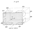
- the x-axis direction correction coil Cx consisting of landing correction coils 215 through 218 and the y-axis direction correction coil Cy consisting of landing correction coils 219 through 222 are arranged at peripheral portions of the cathode ray tube in such a manner that the magnetic fields generated by x-axis direction correction coils 215 through 218 and the magnetic fields generated by y-axis direction correction coils 219 through 222 cross each other at right angles in the same manner as in the first and second embodiments.
- reference numeral 319 denotes an x-y plane component of the geomagnetism
- reference numeral 320 denotes a correction magnetic field vector generated by the landing correction coils
- reference numeral 321 denotes the resultant combined vector of the correction magnetic field generated by the landing correction coil and the geomagnetism
- reference numeral 322 denotes a target value of the vector to which the magnetic field direction and magnetic field intensity shall be adjusted.
- the resultant combined vector 321 of the correction magnetic field 320 and the geomagnetic vector 319 coincide with the target value 322 of the vector
- the resultant combined vector of the z-axis direction component (component in the direction toward the screen) of the geomagnetism and the target value 322 coincides with the electron beam direction to allow the influence of the mislanding due to the geomagnetism to be canceled.
- the control procedure of the operation is as follows. First, the correction magnetic field direction setting section (CMFDS) 212 generates correction magnetic field direction setting data 234 and 235, so that the gain control section (GCS) 211 adjusts the gain of the amplifier sections 209 and 210 by supplying gain control data 236 and 237 to the amplifier sections 210 and 209 so that the data 236 and 237 are used for the gain control of the amplifier sections 209 and 210.
- CMFDS correction magnetic field direction setting section
- GCS gain control section
- the correction magnetic field intensity adjustment section (CMFIAS) 213 generates correction magnetic field intensity adjustment data 239 which is supplied to the amplifier sections 209 and 210, and the ratio of the correction current flowing through the x-axis direction correction coil Cx to the correction current flowing through the y-axis direction correction coil Cy is made constant, thereby allowing the intensity of the correction magnetic field generated by the landing correction coil to be varied while fixing the landing correction magnetic field direction.
- CMFIAS correction magnetic field intensity adjustment section
- the magnetic field direction setting and magnetic field intensity setting operations are effected by means of the control section 214 to successively vary the direction and intensity of the landing correction magnetic field and the instantaneous landing condition on the display screen is evaluated in the color television receiver, so that an optimum correction magnetic field can be determined in algorism.
- the landing correction coil pairs of the x-axis direction correction coil Cx and the y-axis direction correction coil Cy are arranged serving as landing correction means at the peripheral portions of the cathode ray tube as shown in Fig. 6 and the currents flowing through the landing correction coils are controlled in the manner mentioned above, a simple and digitally-controlled landing adjustment can be achieved with high accuracy.
- correction direction (resultant combined vector) and the correction intensity can be controlled arbitrarily in the third embodiment, either one may be only controlled at need.
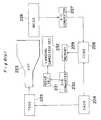
- the present apparatus comprises a cathode ray tube (CRT) 223 for displaying a received video image on the screen of the color television receiver, a correction area designation section (CADS) 224 for designating an area to be subject to landing correction, and a test signal generating section (TSGS) 225 for generating a test signal to be displayed on the screen corresponding to the correction area data designated by the correction area designation section (CADS) 224.
- CTR cathode ray tube
- CADS correction area designation section
- TGS test signal generating section
- the apparatus further comprises a mislanding error detection section (MEDS) 226 for detecting a mislanding error based on the test signal displayed on the television receiver screen, an analog-to-digital converter section 227 for converting the analog mislanding error data into digital data, and a correction data generating section (CDGS) 228 for generating correction magnetic field data corresponding to the correction area designated by the correction area designation section (CADS) 224 depending on the A/D converted mislanding error data.
- the correction magnetic field data generated by the correction data generating section (CDGS) 228 is stored in a memory section 229 corresponding to the designated correction area.
- the correction magnetic field data is converted into an analog value through a digital-to-analog converter section 230, and a drive section 231 receives the analog correction magnetic field data to drive a landing correction section 232 based on the correction magnetic field data.
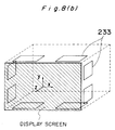
- the landing correction section 232 comprises four pairs of landing correction coils for x-axis direction correction and y-axis direction correction. The arrangement of the x-axis and y-axis direction correction coil pairs is shown in Fig. 8 (b) in the same manner as in the preceding embodiments 1 to 3.
- reference numeral 233 denotes a landing correction coil pair comprised of two coils of the x-axis direction correction coil and y-axis direction correction coil, and the landing correction coil pairs are arranged at the four corners of the peripheral portions of the cathode ray tube in the same manner as in the preceding embodiments.
- the direction and intensity of the correction magnetic field can be independently controlled by means of the landing correction coil pair 233 as described in the third embodiment.
- the procedure of performing a landing adjustment operation on the display screen of the cathode ray tube 223 is as following:
- an area to be subjected to a landing correction is designated by the correction area designation section (CADS) 224.
- the test signal generating section (TSGS) 225 displays a test signal for landing correction in the area to be corrected on the screen of the cathode ray tube 223.
- the mislanding error detection section (MEDS) 226 detects the mislanding error in the area to be corrected.
- the error data detected by the mislanding error detection section (MEDS) 226 is converted into digital data through the analog-to-digital converter section 227 to be supplied to the correction data generating section (CDGS) 228.
- the correction data generating section (CDGS) 228 generates magnetic field intensity data and magnetic field direction data optimum for the correction based on the supplied error data.
- the memory section 229 stores the optimum correction data of the magnetic field intensity and direction data which is supplied on occasion to the drive section 231 via the digital-to-analog converter section 230. Then the drive section 231 drives the landing correction section 232 according to the optimum correction data.
- the landing correction coils are arranged at peripheral portions of the cathode ray tube in the embodiments 1 to 4, it is of course effective that they are arranged in other positions.
- a correction coil pair comprised of the x-axis direction correction coil and the y-axis direction correction coil is provided at each of four peripheral corner portions of the cathode ray tube, and by virtue of the resultant combined vector of the magnetic fields of the x-axis and y-axis direction correction coils, it becomes possible to correct with high accuracy the mislanding attributed to the concentration of the geomagnetism at the peripheral portions of the cathode ray tube due to the influence of the frame and the like.
- the control means controls the drive means to generate a landing correction signal according to the output from the magnetic field detection means, so that the automatical landing correction can be achieved by detecting the magnetic field intensity and direction of the geomagnetism and generating the correction signal corresponding to the detected intensity and direction data of the geomagnetic field.
- the luminance and chromaticity on the screen of the color television display is detected by the mislanding error detection section to obtain the mislanding error, so that a quantitative landing correction can be achieved in a short time with high accuracy by driving the correction coils using a correction signal corresponding to the mislanding error data.
- a high-accuracy landing correction can be achieved by means of an algorithmic control to thereby allow a simple and high-accuracy landing adjustment to be achieved by means of a digital control.
- the mislanding error detection section detects the mislanding error on the display screen of a color television receiver to supply an optimum correction data of the direction and intensity of the correction magnetic field to the landing correction coil pair comprised of the x-axis direction correction coil and the y-axis direction correction coil according to the mislanding error quantity, a high-accuracy automatic landing correction can be achieved providing a great practical effect.
- Any system of the present invention is very effective particularly when it is applied to a shadow mask type CRT for the high-vision system.
Abstract
Description
- The present invention relates to a landing correction apparatus for preventing a possible degradation of chromatic purity caused by an influence of a geomagnetism in a color television receiver.
- Generally in a color television receiver in which a display image is formed on a display screen by scanning phosphor elements through deflection of an electron beam, a landing position of an electron beam is varied by an influence of a geomagnetism to result in a change in luminance and chromaticity of the image picture displayed on the display screen. Particularly in a cathode ray tube for use in a high vision system where high density phosphor elements having a fine pitch is adopted, there occurs a greater degree of a landing error of an electron beam (referred to as "mislanding" hereinafter) due to the influence of the geomagnetism.
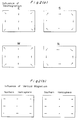
- The degree of electron beam mislanding depends on the arrangement of the phosphor elements. With regard to the arrangement of the phosphor elements, for instance, when comparing a stripe type arrangement as shown in Fig. 9 (a) with a dot type arrangement as shown in Fig. 9 (b), the stripe type arrangement has a greater tolerance for the beam landing because no substantial change takes place in luminance efficiency of the phosphor element when the beam landing position varies in the lengthwise direction of the stripe phosphor element. In Figs. 9(a) and 9(b),
reference numerals reference numerals - The mislanding of electron beams is corrected using a landing correction coil through which an appropriate electric current is flowed for canceling the influence of the geomagnetism. As a conventional electron beam landing correction apparatus, there has been employed, for example, a beam landing correction apparatus for a color cathode ray tube as disclosed in the Japanese Patent (Unexamined) Laid-Open Publication No. HEI 2-29187.
- The above mentioned conventional landing correction apparatus is briefly explained with reference to Figs. 10 through 14.
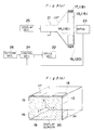
- Referring to Figs. 10 and 12, the apparatus comprises a cathode ray tube (CRT) 101 having a
display panel 101a, adeflection yoke 102, periphery landing correction coils C1 through C6 for correcting the mislanding of electron beams in peripheral portions of the screen, photosensors Ps1 through Ps6 for detecting the mislanding, agun center coil 107 for correcting the mislanding of the electron beams at the center portion of the screen, and ameasurement coil 108 for generating an auxiliary deflection magnetic field for measuring the mislanding amount. The apparatus further comprises a sample/hold circuit (S/H) 109 for sampling and holding an output of each photosensor, amultiplexer 110, an analog-to-digital (A/D)converter 111, adigital calculation circuit 112, ameasurement control circuit 113, ademultiplexer 114, alatch 115, a digital-to-analog (D/A)converter 116, adrive circuit 117 for driving the landing correction coils, and avideo circuit 118 for processing a video signal. - Fig. 11 shows an arrangement of the periphery landing correction coils C1 through C6 for correcting the mislanding of the electron beams at the peripheral portions of the screen.
- Figs. 12 (a) and 12 (b) show an arrangement of photosensors Ps1 through Ps6 for detecting the luminance on the screen. In Fig. 12 (a), the positions of the photosensors Ps1 through Ps6 corresponds to the positions of the landing correction coils C1 through C6 at the peripheral portions of the screen. The photosensors are covered by a
frame member 137. Aphosphor element 139 is provided on the inner surface of thedisplay panel 101a at the face plate of thecathode ray tube 101. - The following describes the operation of the conventional landing correction apparatus having the above-mentioned construction with reference to Figs. 13 and 14. Figs. 13 (a) and 13 (b) are charts for explaining a mislanding detection operation, while Fig. 14 shows a relationship between the beam landing position and the light quantity detected by a photosensor.
- First, regarding a measurement current i which is applied to the mislanding
amount measurement coil 108 from themeasurement control circuit 113, the current i increases in steps from a negative potential region to a positive potential region for measuring the mislanding amount in each field as shown in Fig. 13 (a). In the above case, a control signal e is supplied from themeasurement control circuit 113 to thevideo circuit 118 so that thevideo circuit 118 provides, for example, a video signal for generating a green or white raster to thecathode 101c of thecathode ray tube 101. - According to change of the current flowing through the
measurement coil 108, the deflection center in the deflection yoke position is changed as indicated by the beam loci in Fig. 13 (b). That is, the beam is applied to the position on the screen from acathode 101c passing through anaperture mask 146 and the beam landing position is moved in the horizontal direction of the screen as indicated by arrows in Fig. 13 (b) (vertical direction in the figure).Reference numeral 143 denotes a center beam when no deflection is applied, andnumeral 144 denotes an electron beam deflected by the geomagnetism, andnumeral 145 denotes a mislanding-corrected beam deflected by thegun center coil 107. - Light quantity detection outputs of the photosensors Ps1 through Ps6 are sampled every field in the sample/
hold circuit 109 as shown in Fig. 13 (a), and the sampled data is transmitted via themultiplexer 110 to the analog-to-digital converter 111 and then supplied to thedigital calculation circuit 112 in a form of a digital signal. - The detected light quantity output of the phosphors takes its maximum value at the optimum landing position and gradually decrease as it departs from the optimum landing position as shown in Fig. 14. Since the mislanding amount differs in different portions of the screen, the optimum field number at which the maximum light quantity can be obtained differs in each photosensor.
- The
digital calculation circuit 112 calculates measurement currents i₁, i₂, ..., i₆ corresponding to the position of each of the photosensors Ps1 through Ps6 at which the maximum output is obtained. Furthermore, an average or a weighted average of the current values are calculated to obtain a correction current d₀ to be applied to thegun center coil 107. The correction current d₀ is a direct current which is used for the landing correction in a center area of the screen. - Meanwhile, correction currents d₁, d₂, ..., d₆ are calculated from the measurement currents i₁, i₂, ..., i₆. The correction currents d₁, d₂, ..., d₆ calculated in the
calculation circuit 112 are each output via thedemultiplexer 114 to thelatch circuit 115 and further converted into an analog form by means of the digital-to-analog (D/A)converter 116 to be subsequently supplied via thedrive circuit 117 to each of the periphery landing correction coils C1 through C6. The above-mentioned correction currents d₁, d₂, ..., d₆ are direct currents to be supplied to the correction coils at the peripheral portions of the cathode ray tube to correct the beam mislanding which cannot be removed by thegun center coil 107. - However, in the above-mentioned landing correction coil arrangement as in the conventional example, although the strength of the magnetic field formed by the correction coils can be controlled, the direction of the landing correction magnetic field formed by the correction coils cannot be controlled, and therefore the influence of the geomagnetism directed in a variety of directions cannot be cancelled, resulting in involving a problem that the beam mislanding cannot be corrected with high accuracy.
- Furthermore, the optimum landing position is specified to the point at which the light quantity detected by the photosensor is at its maximum value without taking any matter of chromaticity into consideration, and therefore there also arises another problem that no sufficient uniformity in chromaticity can be achieved in the displayed picture even when a landing correction is effected.
- According to a first aspect of this invention a beam landing correction apparatus for correcting a beam mislanding due to a geomagnetism in a cathode ray tube comprises:
landing correction means including at least a plurality of coil pairs each of which is comprised of two correction coils of which magnetic field axes cross each other at right angles, the correction coil pairs arranged on the peripheral portions of the cathode ray tube;
drive means for supplying a landing correction signal to said landing correction means for correcting the beam mislanding; and
control means for controlling said drive means. - The present invention provides a beam landing correction apparatus which is capable of correcting with high accuracy the influence of the geomagnetism which extends irregularly in a cathode ray tube and which has a higher intensity in the peripheral portions of the cathode ray tube.
- According to a second aspect of the present invention, a beam landing correction apparatus for correcting a beam mislanding due to a geomagnetism in a color television receiver for receiving video information comprises:
display means for displaying the received video information on a display screen in the color television receiver;
landing correction means for correcting the beam mislanding;
drive means for supplying a landing correction signal to said landing correction means;
landing error detection means for detecting beam mislanding quantity based on a luminance and chromaticity distribution in a two-dimensional area on the display screen of said display means;
control means for controlling said drive means according to the detected error data output from said landing error detection means. - The present invention provides a beam landing correction apparatus capable of effecting a quantitative landing correction with high accuracy in a short time by detecting chromaticity data and luminance data on the screen to obtain a beam mislanding amount and to generate a correction current corresponding to the mislanding amount to achieve an automatic correction operation.
- According to a third aspect of the present invention, a beam landing correction apparatus for correcting a beam mislanding due to a geomagnetism in a cathode ray tube comprises:
landing correction means including at least a plurality of landing correction coil pairs each of which is comprised of two correction coils of which correction magnetic field axes cross each other at right angles;
drive means for driving said landing correction means;
correction magnetic field direction setting means for setting a magnetic field direction for the correction magnetic field to be generated by said landing correction means;
correction magnetic field intensity adjustment means for varying the intensity of the correction magnetic field without exerting any substantial influence on the correction magnetic field direction; and
control means for controlling said correction magnetic field direction setting means and said correction magnetic field intensity adjustment means. - The present invention provides a beam landing correction apparatus capable of uniformizing the chromaticity and luminance on the screen by detecting the chromaticity data as well as luminance data of a display image of a video signal on the display screen, obtaining a mislanding amount according to the detected chromaticity and luminance data, and supplying a correction current corresponding to the mislanding amount to the afore-mentioned landing correction coils to effect an automatic landing correction.
- According to a fourth aspect of the present invention, a beam landing correction apparatus for correcting a beam mislanding due to a geomagnetism in a color television receiver for receiving video information comprises:
display means for displaying the received video information on a display screen in the color television receiver;
landing correction means for correcting the beam mislanding;
correction area designation means for designating an area to be subject to landing correction;
test signal generating means for displaying a test signal on the display screen of said display means according to an output of said correction area designation means;
mislanding error detection means for detecting a mislanding error in the correction area designated by said correction area designation means;
correction magnetic field data generating means for generating correction magnetic field data corresponding to the correction area designated by said correction area designation means according to a mislanding error data output from said mislanding error detection means;
memory means for storing the correction magnetic field data generated by said correction magnetic field data generating means; and
drive means for driving said landing correction means according to the correction magnetic field data output from said memory means. - Particular embodiments of the present invention will now be described with reference to the accompanying drawings, in which:-
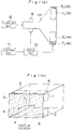
- Fig. 1 (a) is a block diagram of a beam landing correction apparatus in accordance with a first embodiment of the present invention;
- Fig. 1 (b) is a schematic view showing an arrangement of landing correction coils of the first embodiment;
- Figs. 2 (a), 2 (b), and 2 (c) are explanatory views of the operation of the first embodiment;
- Fig. 3 (a) is a block diagram of a modified example of the first embodiment;
- Fig. 3 (b) is a schematic view showing an arrangement of landing correction coils of Fig. 3 (a);
- Fig. 4 (a) is a block diagram of a beam landing correction apparatus in accordance with a second embodiment of the present invention;
- Fig. 4 (b) is a schematic view showing an arrangement of landing correction coils of the second embodiment;
- Fig. 5 is a block diagram of a beam landing correction apparatus in accordance with a third embodiment of the present invention;
- Fig. 6 is a schematic view showing an arrangement of landing correction coils of the third embodiment;
- Fig. 7 is an explanatory view of the operation of the third embodiment;
- Fig. 8 (a) is a block diagram of a beam landing correction apparatus in accordance with a fourth embodiment of the present invention;
- Fig. 8 (b) is a schematic view showing an arrangement of landing correction coils of the fourth embodiment;
- Figs. 9 (a) and 9 (b) are explanatory views of tolerances in beam landing in different arrangements of phosphor elements;
- Fig. 10 is a block diagram of a conventional beam landing correction apparatus;
- Fig. 11 is a schematic view showing an arrangement of landing correction coils of the conventional apparatus;
- Figs. 12 (a) and 12 (b) are schematic views showing an arrangement of photosensors in the conventional apparatus;
- Fig. 13 (a) and 13 (b) are explanatory views of the operation of the conventional apparatus; and
- Fig. 14 is an explanatory view showing a relationship between the light quantity and the beam landing positions in the conventional apparatus.
- The following describes a first embodiment of a beam landing correction apparatus according to the present invention with reference to Figs. 1 through 3.
- Referring to Figs. 1(a) and 1(b), the beam landing correction apparatus of the first embodiment comprises a plurality of landing correction coils arranged on peripheral portions of a cathode ray tube (CRT), where the landing correction coils consist of x-axis direction correction coils 1 through 4 for correcting mislanding in the x-axis direction and y-axis direction correction coils 5 through 8 for correcting mislanding in the y-axis direction.
- The landing correction coils 1 through 8 are arranged by pairing each of the x-axis direction correction coils 1 through 4 with each of the y-axis direction correction coils 5 through 8 at four peripheral corner portions of the cathode ray tube because large mislanding of electron beams is caused due to a concentration of the geomagnetism at the peripheral portions of the cathode ray tube by an influence of a frame member and the like supporting the cathode ray tube. The x-axis direction correction coils and the y-axis direction correction coils are arranged at peripheral portions of the cathode ray tube in such a manner that the magnetic fields generated by the x-axis direction correction coils and the magnetic fields generated by the y-axis direction correction coils cross each other at right angles.
- The apparatus further comprises a static
landing correction coil 9 for correcting static mislanding of electron beams, which is arranged at a neck portion of the cathode ray tube. - The apparatus is further comprised of a
drive section 10 for supplying an electric correction signal to each of the landing correction coils 1 through 9, acontrol section 11 for controlling thedrive section 10 to generate an appropriate correction signal to be supplied to thedrive section 10 so as to cancel the influence of the geomagnetism, and adisplay section 12 for supplying a video signal to the cathode ray tube to display an image of the video signal on a screen of the cathode ray tube. - The following describes the operation of the beam landing correction apparatus of the first embodiment having the construction mentioned above.
- In the first embodiment, by arranging a plurality of landing correction coil pairs provided by pairing each of the x-axis direction correction coils 1 through 4 with each of the y-axis direction correction coils 5 through 8 at four peripheral corner portions of the cathode ray tube, the mislanding of beams can be corrected with high accuracy using the resultant correction magnetic field combination of the x-axis component and y-axis component of the correction magnetic field. For example, a pair of the x-axis
direction correction coil 1 and the y-axisdirection correction coil 6 serve as a landing correction coil pair for correcting the beam mislanding in the upper right portion of the screen of the cathode ray tube in the figure. - The following describes in detail the above-mentioned operation with reference to Figs. 2 (a) through 2 (c).
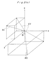
- Figs. 2 (a) and 2 (b) show the influence of the geomagnetism exerted on the electron beam movement. Figs. 2 (a) shows the influence of the geomagnetic field in different geographical directions East, West, South and North and Figs. 2 (b) shows the influence of the vertical magnetic fields exerted on the movement of an electron beam, where the electron beam on the screen receives different influence depending on the geographical direction and the northern or southern hemispheric condition.
- Particularly, in a cathode ray tube (CRT) having a fine shadow mask pitch, the influence of the geomagnetism exerted on the beam movement is an important factor in terms of color purity. Therefore, a uniform image can be displayed by performing landing corrections particularly at peripheral portions with landing correction coils arranged at the peripheral four corner portions of the screen to completely effect cancellation of the influence of the geomagnetism. It is noted here that the cancellation of the influence of the geomagnetism can be achieved by controlling the polarity and the quantity of a direct current potential to be supplied to the landing correction coils in each direction.
- Referring to Fig. 2 (c),
reference numeral 40 denotes a geomagnetism vector causing a beam mislanding, whilereference numeral 41 denotes an electron beam vector. The beam mislanding occurs for the reason that the Lorentz's force is exerted on the electron beam to displace the landing position of the electron beam in the cathode ray tube. In order to remove the mislanding of the electron beam, there are two methods, one for removing the geomagnetic vector to be zero, and the other for making thegeomagnetic vector 40 coincide with theelectron beam vector 41. The following describes the latter method in more detail. - Assuming now that the
geomagnetic vector 40 and theelectron beam vector 41 meet at an angle ϑ, the magnitude of the Lorentz's force causing the beam mislanding depends on the value of sin ϑ. In other words, the Lorentz's force can be made zero when the geomagnetic direction and the electron beam direction coincide with each other. By this way, the occurrence of the mislanding due to the geomagnetism can be prevented. - In order to effect the former one of the above-mentioned two mislanding cancellation methods, there must be employed three-dimensional correction coil means for correcting the beam mislanding in the x-, y-, and z-axes directions. However, it is difficult to provide the z-direction correction coil without preventing the electron beam projection to the screen regarding the construction of the color television receiver, and therefore the latter method is more practical.
- For the above reasons, it is necessary to provide landing correction coil pairs capable of generating magnetic fields in the x-axis and y-axis directions in order to achieve a high-accuracy correction with cancellation of the influence of the geomagnetism, and therefore it is required to vary the component force in the x-y plane of the geomagnetic vector by means of the resultant combined vector of correction component forces in the x-axis and y-axis directions to make the geomagnetic direction coincide with the electron beam direction.
- Taking the aforementioned factors of the beam mislanding due to the geomagnetism into account, it is impossible to make the geomagnetic direction coincide with the electron beam direction even by fixing the magnetic field direction generated by the landing correction coil and varying the magnitude of the magnetic field as exemplified in Fig. 1 (b). In other words, a high-accuracy correction can be achieved by varying the magnitude and direction of the correction magnetic field vector generated by the x-axis direction correction coil and the y-axis direction correction coil to vary the geomagnetic direction thereby making the geomagnetic direction coincide with the electron beam direction.
- Further by providing the peripheral landing correction coils 1 through 8 as in the present embodiment, it becomes possible to reduce a correlation on the display screen of a color television, i.e., it is possible to prevent a phenomenon that a correction effected at a portion increases a mislanding amount at another portion. In the present embodiment, further the
static correction coil 9 is provided at the neck portion of the cathode ray tube to permit a static correction of the beam mislanding. - Figs. 3 (a) and 3 (b) show a modified example of the landing correction apparatus having the same construction as that of the first embodiment except employing a magnetic field detecting section (MFDS) and a geomagnetism direction setting section. Referring to Figs. 3 (a) and 3 (b), the beam landing correction apparatus comprises partial landing correction coils 13 through 20, a
static correction coil 21, adrive section 22 for supplying a correction current signal to the above-mentioned correction coils, in the same manner as that of the first embodiment. The apparatus further comprises a magnetic field detection section (MFDS) 23 for externally detecting the intensity and direction of the geomagnetism at various portions of the display screen, acontrol section 24 for controlling thedrive section 22 by generating a control signal in response to receiving the geomagnetic field intensity and direction output from the magneticfield detection section 23, adisplay section 25 for displaying an image on the screen of the cathode ray tube, and asetting section 26 for manually setting the direction of the geomagnetism, thereby to achieve an automatic landing correction. - The following describes the operation of the landing correction apparatus having the construction mentioned above. The automatic landing correction of the landing correction apparatus is realized by providing the magnetic
field detection section 23 for detecting the intensity and direction of the geomagnetism. The output of the magnetic field detection section (MFDS) 23 is transmitted to thecontrol section 24 which generates a control signal according to the received detection values of the intensity and direction of the geomagnetism thereby to control thedrive section 22 for supplying a correction current signal to each of the correction coils 13 through 20 and 21. It is noted that correction data corresponding to the intensity and direction of the geomagnetism are already stored in thecontrol section 24 as described in the first embodiment. It is also possible to manually set the direction of the geomagnetism by providing thesetting section 26. - Although the partial landing correction coils 1 through 8 and 13 through 20 have rectangular shapes in the present embodiment, it is of course effective that they have other shapes.
- Fig. 4 (a) shows a beam landing correction apparatus in accordance with a second embodiment of the present invention, while Fig. 4 (b) shows an arrangement of the partial landing correction coils, which has a similar construction to that of the first embodiment except employing a mislanding error detection section (MEDS). Referring to Figs. 4 (a) and 4 (b), the present apparatus comprises peripheral landing correction coils 27 through 34, a
static correction coil 35, adrive section 36 for supplying a correction current to the above-mentioned correction coils in the same manner as that of the first embodiment. The apparatus further comprises a mislanding error detection section (MEDS) 37 for detecting the luminance and chromaticity on the screen of the color television display to detect a mislanding of an electron beam, acontrol section 38 for generating a control signal according to an output from the mislanding error detection section (MEDS) 37 to control thedrive section 36, and adisplay section 39 for displaying an image on the screen of the cathode ray tube. - The following describes the operation of the landing correction apparatus of the second embodiment having the construction mentioned above. By arranging the mislanding error detection section (MEDS) 37 at a portion to be subjected to a landing correction, the luminance and chromaticity data at the portion to be corrected is taken in by means of a photoelectric transfer element PE to detect the beam mislanding according to the luminance and chromaticity data obtained. The mislanding error detected by the detection section (MEDS) 37 is transmitted to the
control section 38, which generates a control signal according to the mislanding error data output from the detection section (MEDS) 37 to control thedrive section 36 thereby to effect an automatical landing correction. - As described above, according to the present embodiment, it becomes possible to automatically perform a landing correction with high accuracy and quantitative correction to be effected in a short time.
- The following describes the operation of the
control section 38 in detail. Although the amount of the mislanding error is evaluated based on the luminance and chromaticity data in the present embodiment, it is necessary to determine a convergence condition which is the decisive factor in the automatical landing correction. - Therefore, the mislanding error is obtained according to the equations as follows.

where Y and r represent respectively an error in luminance and an error in chromaticity with respect to reference values, Y₁ represents the luminance at the correction point, x and y represent the chromaticity values at the correction point, Y₀ represents the reference value in luminance, and x₀ and y₀ represent the reference values in chromaticity. - By obtaining the mislanding error at the correction point according to the above equations, the
control section 38 generates the control signal to control thedrive section 36 which generates an electric correction current to be flowed through each of the landing correction coils 27 through 34 and 35 such that the mislanding evaluation amount at the correction point comes closer to the reference value. In the present case, the convergence condition is determined while attaching great importance to the chromaticity, i.e., the value r in the above equation. This is because the chromaticity does not always come closest to the reference value at the point where the maximum luminance is achieved, and making much of the uniformity on the display screen in a color television receiver, the convergence condition should be determined putting more weight on the chromaticity. - A concrete convergence condition is determined as follows. That is, the point at which the error in chromaticity r is in a specified permissive range and the maximum luminance is achieved in the same range is determined to be the convergence point. In the above case, according to the result of a visual image quality evaluation experiment, it is appropriate that the value r, i.e., a distance from the reference value is within 0.01 on the chromaticity diagram in determining the above-mentioned permissive range.
- In a manner as described above, the mislanding correction is performed by obtaining the mislanding error on the display screen of the color television receiver to be corrected by the
control section 38 and by applying an electric correction signal corresponding to the detected mislanding error flowing through the correction coils 27 through 34 and 35 to determine the optimum convergence point. The procedure of the landing correction is that, a static landing correction at the center of the screen of the color television receiver is firstly effected, and thereafter a partial landing correction is effected at the peripheral portions of the screen. - Although the correction is effected with more weight put on the chromaticity between the luminance and chromaticity in the two-dimensional area of an image in the second embodiment, the correction may be effected putting more weight on the luminance at need.
- Figs. 5 through 7 shows a beam landing correction apparatus in accordance with a third embodiment of the present invention.
- In Fig. 5, the apparatus comprises an x-axis direction correction coil Cx for correcting a mislanding in a horizontal direction on the screen of the cathode ray tube and a y-axis direction correction coil Cy for correcting a mislanding in a vertical direction on the screen of the cathode ray tube. The apparatus also comprises
amplifier sections amplifier sections control section 214 for controlling the correction magnetic field direction setting section (CMFDS) 212 and the correction magnetic field intensity adjustment section (CMFIAS) 213. - Referring to Fig. 6, the x-axis direction correction coil Cx consisting of landing correction coils 215 through 218 and the y-axis direction correction coil Cy consisting of landing correction coils 219 through 222 are arranged at peripheral portions of the cathode ray tube in such a manner that the magnetic fields generated by x-axis direction correction coils 215 through 218 and the magnetic fields generated by y-axis direction correction coils 219 through 222 cross each other at right angles in the same manner as in the first and second embodiments.
- The following describes the operation of the landing correction apparatus of the third embodiment having a construction as mentioned above.
- Referring to Fig. 7, it is assumed that,
reference numeral 319 denotes an x-y plane component of the geomagnetism,reference numeral 320 denotes a correction magnetic field vector generated by the landing correction coils,reference numeral 321 denotes the resultant combined vector of the correction magnetic field generated by the landing correction coil and the geomagnetism, andreference numeral 322 denotes a target value of the vector to which the magnetic field direction and magnetic field intensity shall be adjusted. When the resultant combinedvector 321 of the correctionmagnetic field 320 and thegeomagnetic vector 319 coincide with thetarget value 322 of the vector, the resultant combined vector of the z-axis direction component (component in the direction toward the screen) of the geomagnetism and thetarget value 322 coincides with the electron beam direction to allow the influence of the mislanding due to the geomagnetism to be canceled. - The control procedure of the operation is as follows. First, the correction magnetic field direction setting section (CMFDS) 212 generates correction magnetic field
direction setting data amplifier sections gain control data amplifier sections data amplifier sections intensity adjustment data 239 which is supplied to theamplifier sections - In other words, by varying the correction magnetic field intensity with the correction magnetic field direction fixed, it becomes possible to determine whether or not the correction magnetic field intensity can be adjusted to the
target vector value 322 in the correction magnetic field direction. Therefore, the magnetic field direction setting and magnetic field intensity setting operations are effected by means of thecontrol section 214 to successively vary the direction and intensity of the landing correction magnetic field and the instantaneous landing condition on the display screen is evaluated in the color television receiver, so that an optimum correction magnetic field can be determined in algorism. - As described above, the landing correction coil pairs of the x-axis direction correction coil Cx and the y-axis direction correction coil Cy are arranged serving as landing correction means at the peripheral portions of the cathode ray tube as shown in Fig. 6 and the currents flowing through the landing correction coils are controlled in the manner mentioned above, a simple and digitally-controlled landing adjustment can be achieved with high accuracy.
- Although the correction direction (resultant combined vector) and the correction intensity can be controlled arbitrarily in the third embodiment, either one may be only controlled at need.
- The following describes a beam landing correction apparatus in accordance with a fourth embodiment of the present invention with reference to Figs. 8 (a) and 8 (b).
- Referring to Fig. 8 (a), the present apparatus comprises a cathode ray tube (CRT) 223 for displaying a received video image on the screen of the color television receiver, a correction area designation section (CADS) 224 for designating an area to be subject to landing correction, and a test signal generating section (TSGS) 225 for generating a test signal to be displayed on the screen corresponding to the correction area data designated by the correction area designation section (CADS) 224. The apparatus further comprises a mislanding error detection section (MEDS) 226 for detecting a mislanding error based on the test signal displayed on the television receiver screen, an analog-to-
digital converter section 227 for converting the analog mislanding error data into digital data, and a correction data generating section (CDGS) 228 for generating correction magnetic field data corresponding to the correction area designated by the correction area designation section (CADS) 224 depending on the A/D converted mislanding error data. The correction magnetic field data generated by the correction data generating section (CDGS) 228 is stored in amemory section 229 corresponding to the designated correction area. The correction magnetic field data is converted into an analog value through a digital-to-analog converter section 230, and adrive section 231 receives the analog correction magnetic field data to drive alanding correction section 232 based on the correction magnetic field data. Thelanding correction section 232 comprises four pairs of landing correction coils for x-axis direction correction and y-axis direction correction. The arrangement of the x-axis and y-axis direction correction coil pairs is shown in Fig. 8 (b) in the same manner as in the precedingembodiments 1 to 3. - Referring to Fig. 8 (b),
reference numeral 233 denotes a landing correction coil pair comprised of two coils of the x-axis direction correction coil and y-axis direction correction coil, and the landing correction coil pairs are arranged at the four corners of the peripheral portions of the cathode ray tube in the same manner as in the preceding embodiments. - The following describes the operation of the landing correction apparatus of the fourth embodiment constructed as mentioned above.
- The direction and intensity of the correction magnetic field can be independently controlled by means of the landing
correction coil pair 233 as described in the third embodiment. The procedure of performing a landing adjustment operation on the display screen of thecathode ray tube 223 is as following: - Firstly, an area to be subjected to a landing correction is designated by the correction area designation section (CADS) 224. According to the correction area data designated by the correction area designation section (CADS) 224, the test signal generating section (TSGS) 225 displays a test signal for landing correction in the area to be corrected on the screen of the
cathode ray tube 223. With the test signal displayed on the screen, the mislanding error detection section (MEDS) 226 detects the mislanding error in the area to be corrected. - The error data detected by the mislanding error detection section (MEDS) 226 is converted into digital data through the analog-to-
digital converter section 227 to be supplied to the correction data generating section (CDGS) 228. The correction data generating section (CDGS) 228 generates magnetic field intensity data and magnetic field direction data optimum for the correction based on the supplied error data. Thememory section 229 stores the optimum correction data of the magnetic field intensity and direction data which is supplied on occasion to thedrive section 231 via the digital-to-analog converter section 230. Then thedrive section 231 drives thelanding correction section 232 according to the optimum correction data. - By constructing the landing correction apparatus in the manner as described above in the fourth embodiment of the present invention, a high-accuracy automatic landing correction can be performed.
- Although a digital processing correction system is adopted in the fourth embodiment, the same effect can be achieved by means of an analog processing circuit.
- Although the landing correction coils are arranged at peripheral portions of the cathode ray tube in the
embodiments 1 to 4, it is of course effective that they are arranged in other positions. - As described above, according to the first aspect of the present invention, a correction coil pair comprised of the x-axis direction correction coil and the y-axis direction correction coil is provided at each of four peripheral corner portions of the cathode ray tube, and by virtue of the resultant combined vector of the magnetic fields of the x-axis and y-axis direction correction coils, it becomes possible to correct with high accuracy the mislanding attributed to the concentration of the geomagnetism at the peripheral portions of the cathode ray tube due to the influence of the frame and the like.
- Furthermore, by adopting an arrangement where the magnetic field detection means (23) is provided for detecting the direction and magnetic field intensity of the geomagnetism at a specified position of the color television receiver, the control means controls the drive means to generate a landing correction signal according to the output from the magnetic field detection means, so that the automatical landing correction can be achieved by detecting the magnetic field intensity and direction of the geomagnetism and generating the correction signal corresponding to the detected intensity and direction data of the geomagnetic field.
- According to the second aspect of the present invention, the luminance and chromaticity on the screen of the color television display is detected by the mislanding error detection section to obtain the mislanding error, so that a quantitative landing correction can be achieved in a short time with high accuracy by driving the correction coils using a correction signal corresponding to the mislanding error data.
- According to the third aspect of the present invention, by successively controlling at control terminals the magnetic field direction and magnetic field intensity of the correction magnetic field formed by each correction coil, a high-accuracy landing correction can be achieved by means of an algorithmic control to thereby allow a simple and high-accuracy landing adjustment to be achieved by means of a digital control.
- According to the fourth aspect of the present invention, the mislanding error detection section detects the mislanding error on the display screen of a color television receiver to supply an optimum correction data of the direction and intensity of the correction magnetic field to the landing correction coil pair comprised of the x-axis direction correction coil and the y-axis direction correction coil according to the mislanding error quantity, a high-accuracy automatic landing correction can be achieved providing a great practical effect. Any system of the present invention is very effective particularly when it is applied to a shadow mask type CRT for the high-vision system.
Claims (10)
- A beam landing correction apparatus for correcting a beam mislanding due to a geomagnetism in a cathode ray tube comprising:
landing correction means including at least a plurality of coil pairs (1 through 8) each of which is comprised of two correction coils of which magnetic field axes cross each other at right angles, the correction coil pairs arranged on the peripheral portions of the cathode ray tube;
drive means (10) for supplying a landing correction signal to said landing correction means for correcting the beam mislanding; and
control means (11) for controlling said drive means. - The beam landing correction apparatus as claimed in Claim 1, wherein said landing correction means further comprises a static correction coil (9) arranged at a neck portion of the cathode ray tube.
- The beam landing correction apparatus as claimed in Claim 1, wherein said landing correction means comprises magnetic field detection means (23) for detecting the direction and intensity of the geomagnetic field at a specified position of the cathode ray tube and said control means controls said drive means to generate a landing correction signal according to the output data of the direction and intensity of the geomagnetic field generated from said magnetic field detection means.
- A beam landing correction apparatus for correcting a beam mislanding due to a geomagnetism in a color television receiver for receiving video information comprising:
display means (39, CRT) for displaying the received video information on a display screen in the color television receiver;
landing correction means (27 through 34, 35) for correcting the beam mislanding;
drive means (36) for supplying a landing correction signal to said landing correction means;
landing error detection means (37) for detecting beam mislanding quantity based on a luminance and chromaticity distribution in a two-dimensional area on the display screen of said display means;
control means (38) for controlling said drive means according to the detected error data output from said landing error detection means. - The beam landing correction apparatus as claimed in Claim 4, wherein said landing error detection means includes a photoelectric transfer element for detecting the luminance and chromaticity distribution on the display screen to be transferred to an electrical output data of the mislanding quantity.
- The beam landing correction apparatus as claimed in Claim 4, wherein said landing error detection means obtains the landing error attributed to the beam mislanding based on the luminance and chromaticity data with respect to specified reference values of the luminance and chromaticity and the obtained landing error data is supplied to said control means.
- A beam landing correction apparatus for correcting a beam mislanding due to a geomagnetism in a cathode ray tube comprising:
landing correction means (Cx, Cy) including at least a plurality of landing correction coil pairs (215/219 through 218/222) each of which is comprised of two correction coils of which correction magnetic field axes cross each other at right angles;
drive means (209, 210, 211) for driving said landing correction means;
correction magnetic field direction setting means (212) for setting a magnetic field direction for the correction magnetic field to be generated by said landing correction means;
correction magnetic field intensity adjustment means (213) for varying the intensity of the correction magnetic field without exerting any substantial influence on the correction magnetic field direction; and
control means (214) for controlling said correction magnetic field direction setting means and said correction magnetic field intensity adjustment means. - The beam landing correction apparatus as claimed in Claim 7, wherein said control means controls said correction magnetic field direction setting means and said correction magnetic field intensity adjustment means in a sequential manner.
- A beam landing correction apparatus for correcting a beam mislanding due to a geomagnetism in a color television receiver for receiving video information comprising:
display means (223 CRT) for displaying the received video information on a display screen in the color television receiver;
landing correction means (232) for correcting the beam mislanding;
correction area designation means (224) for designating an area to be subject to landing correction; test signal generating means (225) for displaying a test signal on the display screen of said display means according to an output of said correction area designation means;
mislanding error detection means (226) for detecting a mislanding error in the correction area designated by said correction area designation means;
correction magnetic field data generating means (228) for generating correction magnetic field data corresponding to the correction area designated by said correction area designation means according to a mislanding error data output from said mislanding error detection means;
memory means (229) for storing the correction magnetic field data generated by said correction magnetic field data generating means; and
drive means (231) for driving said landing correction means according to the correction magnetic field data output from said memory means. - The beam landing correction apparatus as claimed in Claim 9, wherein said correction magnetic field data generating means generates magnetic field direction data and magnetic field intensity data of the correction magnetic field corresponding to the quantity of the mislanding error in the area to be subject to the landing correction.
Applications Claiming Priority (4)
| Application Number | Priority Date | Filing Date | Title |
|---|---|---|---|
| JP4022391A JPH05219516A (en) | 1992-02-07 | 1992-02-07 | Landing correcting device |
| JP22391/92 | 1992-02-07 | ||
| JP4243050A JPH0698340A (en) | 1992-09-11 | 1992-09-11 | Landing correction device |
| JP243050/92 | 1992-09-11 |
Publications (2)
| Publication Number | Publication Date |
|---|---|
| EP0555094A2 true EP0555094A2 (en) | 1993-08-11 |
| EP0555094A3 EP0555094A3 (en) | 1994-03-16 |
Family
ID=26359599
Family Applications (1)
| Application Number | Title | Priority Date | Filing Date |
|---|---|---|---|
| EP93300876A Withdrawn EP0555094A2 (en) | 1992-02-07 | 1993-02-05 | Beam landing correction apparatus for a cathode ray tube |
Country Status (2)
| Country | Link |
|---|---|
| EP (1) | EP0555094A2 (en) |
| KR (1) | KR970000847B1 (en) |
Cited By (3)
| Publication number | Priority date | Publication date | Assignee | Title |
|---|---|---|---|---|
| DE19926487A1 (en) * | 1999-06-10 | 2000-12-14 | Thomson Brandt Gmbh | Digital convergence correction method for television projection, involves using separate RGB optical sensors around unseen edge of screen to determine convergence correction values |
| US6671004B1 (en) | 1999-06-10 | 2003-12-30 | Thomson Licensing S.A. | Method and apparatus for convergence correction in a television set |
| US6750921B1 (en) | 1999-06-30 | 2004-06-15 | Thomson Licensing S.A. | Projection video display with photo transistor sensors |
Citations (4)
| Publication number | Priority date | Publication date | Assignee | Title |
|---|---|---|---|---|
| US3588583A (en) * | 1968-07-16 | 1971-06-28 | Thomson Csf | Magnetic elements mounted on the corners of the screen of color television tubes for compensating for the effect of the terrestrial magnetic field |
| EP0077112A1 (en) * | 1981-10-09 | 1983-04-20 | Hazeltine Corporation | External magnetic field compensator for a CRT |
| JPH0229187A (en) * | 1988-07-19 | 1990-01-31 | Sony Corp | Beam landing correcting device for color cathode-ray tube |
| EP0396381A2 (en) * | 1989-05-01 | 1990-11-07 | Conrac Scd, Inc. | Method and apparatus for dynamic magnetic field neutralization |
-
1993
- 1993-02-05 EP EP93300876A patent/EP0555094A2/en not_active Withdrawn
- 1993-02-06 KR KR93001614A patent/KR970000847B1/en not_active IP Right Cessation
Patent Citations (4)
| Publication number | Priority date | Publication date | Assignee | Title |
|---|---|---|---|---|
| US3588583A (en) * | 1968-07-16 | 1971-06-28 | Thomson Csf | Magnetic elements mounted on the corners of the screen of color television tubes for compensating for the effect of the terrestrial magnetic field |
| EP0077112A1 (en) * | 1981-10-09 | 1983-04-20 | Hazeltine Corporation | External magnetic field compensator for a CRT |
| JPH0229187A (en) * | 1988-07-19 | 1990-01-31 | Sony Corp | Beam landing correcting device for color cathode-ray tube |
| EP0396381A2 (en) * | 1989-05-01 | 1990-11-07 | Conrac Scd, Inc. | Method and apparatus for dynamic magnetic field neutralization |
Non-Patent Citations (1)
| Title |
|---|
| PATENT ABSTRACTS OF JAPAN vol. 14, no. 175 (E-914)6 April 1990 & JP-A-02 029 187 (SONY CORP.) * |
Cited By (3)
| Publication number | Priority date | Publication date | Assignee | Title |
|---|---|---|---|---|
| DE19926487A1 (en) * | 1999-06-10 | 2000-12-14 | Thomson Brandt Gmbh | Digital convergence correction method for television projection, involves using separate RGB optical sensors around unseen edge of screen to determine convergence correction values |
| US6671004B1 (en) | 1999-06-10 | 2003-12-30 | Thomson Licensing S.A. | Method and apparatus for convergence correction in a television set |
| US6750921B1 (en) | 1999-06-30 | 2004-06-15 | Thomson Licensing S.A. | Projection video display with photo transistor sensors |
Also Published As
| Publication number | Publication date |
|---|---|
| KR970000847B1 (en) | 1997-01-20 |
| EP0555094A3 (en) | 1994-03-16 |
| KR930019042A (en) | 1993-09-22 |
Similar Documents
| Publication | Publication Date | Title |
|---|---|---|
| EP0498659B1 (en) | Adjustment apparatus for video display means | |
| US5583401A (en) | Beam landing correction apparatus for a cathode ray tube | |
| US5497054A (en) | Automatic digital convergence correcting method and apparatus therefor | |
| KR20040086387A (en) | Method and apparatus for automatically adjusting the raster in projection television receivers | |
| EP0555094A2 (en) | Beam landing correction apparatus for a cathode ray tube | |
| KR100560591B1 (en) | Adaptive convergence adjustment for multi-scan monitor | |
| US5536192A (en) | Method for measuring convergence of a color cathode ray tube and apparatus thereof | |
| US4988857A (en) | Misconvergence measuring apparatus | |
| US5642175A (en) | Color cathode ray tube display device and method of eliminating the influence of an external magnetic field | |
| GB2360430A (en) | Convergence measuring system | |
| EP0660364B1 (en) | Display device comprising a deflection unit | |
| JP3269166B2 (en) | Image quality measuring apparatus and method for color cathode ray tube | |
| US6680757B1 (en) | Environmental magnetism compensating device and cathode-ray tube display device | |
| JPH05219516A (en) | Landing correcting device | |
| KR0160609B1 (en) | Automatic digital convergence compensation method | |
| JP3360840B2 (en) | Mislanding measurement system for color cathode ray tube display | |
| JP3320926B2 (en) | Color CRT and its adjustment method | |
| JPH03119892A (en) | Convergence measuring device | |
| JPH0698340A (en) | Landing correction device | |
| JP3269318B2 (en) | Automatic geomagnetic compensator | |
| JP2713981B2 (en) | Focus voltage adjustment device | |
| JP2000115816A (en) | Device and method for assisting image quality adjustment of color cathode-ray tube and color cathode-ray tube | |
| JPS6154318B2 (en) | ||
| JPH02244539A (en) | Chromatic observation adjusting device for color cathode-ray tube | |
| JPH04326693A (en) | Picture correcting device |
Legal Events
| Date | Code | Title | Description |
|---|---|---|---|
| PUAI | Public reference made under article 153(3) epc to a published international application that has entered the european phase |
Free format text: ORIGINAL CODE: 0009012 |
|
| 17P | Request for examination filed |
Effective date: 19930226 |
|
| AK | Designated contracting states |
Kind code of ref document: A2 Designated state(s): DE GB NL |
|
| PUAL | Search report despatched |
Free format text: ORIGINAL CODE: 0009013 |
|
| AK | Designated contracting states |
Kind code of ref document: A3 Designated state(s): DE GB NL |
|
| 17Q | First examination report despatched |
Effective date: 19990331 |
|
| STAA | Information on the status of an ep patent application or granted ep patent |
Free format text: STATUS: THE APPLICATION IS DEEMED TO BE WITHDRAWN |
|
| 18D | Application deemed to be withdrawn |
Effective date: 19990811 |