EP0555023B1 - Pattern recognition - Google Patents
Pattern recognition Download PDFInfo
- Publication number
- EP0555023B1 EP0555023B1 EP93300674A EP93300674A EP0555023B1 EP 0555023 B1 EP0555023 B1 EP 0555023B1 EP 93300674 A EP93300674 A EP 93300674A EP 93300674 A EP93300674 A EP 93300674A EP 0555023 B1 EP0555023 B1 EP 0555023B1
- Authority
- EP
- European Patent Office
- Prior art keywords
- pattern
- pattern recognition
- recognition
- patterns
- dictionary
- Prior art date
- Legal status (The legal status is an assumption and is not a legal conclusion. Google has not performed a legal analysis and makes no representation as to the accuracy of the status listed.)
- Expired - Lifetime
Links
Images


Classifications
-
- G—PHYSICS
- G06—COMPUTING; CALCULATING OR COUNTING
- G06V—IMAGE OR VIDEO RECOGNITION OR UNDERSTANDING
- G06V30/00—Character recognition; Recognising digital ink; Document-oriented image-based pattern recognition
- G06V30/10—Character recognition
- G06V30/24—Character recognition characterised by the processing or recognition method
- G06V30/242—Division of the character sequences into groups prior to recognition; Selection of dictionaries
Definitions
- the present invention relates to a method of pattern recognition and an apparatus for recognizing patterns.
- the present invention relates to a method and apparatus which adapts to the characteristics of an unknown pattern, wherein said pattern is required to be recognized.
- an unknown pattern for example, a pattern derived from an image scanner or received by facsimile transmission, is analyzed to determine the identity of the pattern.
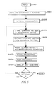
- Figure 16 illustrates a typical pattern recognition process, which identifies individual characters in an image containing a plurality of such characters.
- an image derived for example, from an image scanner, is input in step S1601 and the individual characters in the image are segmented in step S1602.
- Steps S1601 and S1602 are typically performed by a general purpose host computer which then transmits the characters segmented in step S1602 to a dedicated optical character recognition device.
- the optical character recognition device subjects the segmented characters to feature extraction whereby a feature vector is derived for the unknown pattern.
- the feature vector represents various features concerning the pattern such as stroke position, direction, length, and so forth.
- rough classification step 1604 the feature vector for the unknown pattern is then compared to a dictionary which contains plural feature vectors for standard patterns.
- the feature vector for the unknown pattern is compared with each feature vector in the standard pattern dictionary and a distance value is calculated representing the mathematical distance between the feature vector for the unknown pattern and the feature vector for the standard pattern.
- the distance values are sorted and the best candidates, for example, the 52 candidates that are nearest to the feature vector for the unknown pattern, are selected.
- the best candidates are subjected to detailed classification.
- additional discriminant functions for example a pseudo-bayesian discriminant function, are employed to select the best candidate or candidates from among those determined in the rough classification step.
- the best candidate or candidates for the unknown pattern are then transmitted back to the general purpose host computer where they are subjected to post processing in step S1606.
- Post processing typically entails processing such as spell-checking, context checking and syntax processing and results in selection of one candidate for the unknown pattern.
- Japanese Patent Abstract No. JP-A-59045585 discloses a character recognizing device in which in order to improve scanning efficiency dictionary data stored in a main dictionary memory is replaced with dictionary data stored in an auxiliary dictionary memory when a predetermined number of reject characters have been counted by a counter.
- the present invention provides a method of pattern recognition as set out in claim 11.
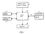
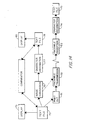
- Figure 1 is an overall block diagram of a pattern recognition apparatus according to the present invention.
- the pattern recognition system includes a host CPU 10 such as an EZPS3500 programmable microprocessor, an image data input device 11 such as an image scanner or facsimile reception unit, an image memory 12 for storing image data input by the input device, a character recognition device 14 for recognizing unknown patterns transferred by host CPU 10 over SCSI interface 13 and transferring candidates for the unknown pattern back to the host CPU over interface 13, a character memory 15 for storing the candidates transmitted from the character recognition device, and a display 16 for displaying the pattern recognition results.
- a host CPU 10 such as an EZPS3500 programmable microprocessor
- an image data input device 11 such as an image scanner or facsimile reception unit
- an image memory 12 for storing image data input by the input device
- a character recognition device 14 for recognizing unknown patterns transferred by host CPU 10 over SCSI interface 13 and transferring candidates for the unknown pattern back to the host CPU over interface 13
- a character memory 15 for storing the candidates transmitted from the character recognition device
- a display 16 for displaying the pattern recognition results.
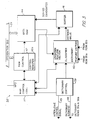
- FIG. 2 is a detailed block diagram of character recognition device 14.
- character recognition device 14 is comprised by a communication part and a recognition part.
- the communication part includes a communication bus 20 to which are connected a microprocessor 21 such as a 68000 programmable microprocessor, a programmable read only memory (“PROM”) 22 for storing process steps for execution by microprocessor 21, a buffer memory 24 for buffering communication to and from host CPU 10, a DMA controller 25 for controlling direct memory access with host CPU 10, an SCSI controller 26 for communication with host CPU 10 over interface 13, and an internal buffer memory 27 for providing internal buffering between the communication part and the recognition part.
- a microprocessor 21 such as a 68000 programmable microprocessor
- PROM programmable read only memory
- buffer memory 24 for buffering communication to and from host CPU 10
- DMA controller 25 for controlling direct memory access with host CPU 10
- SCSI controller 26 for communication with host CPU 10 over interface 13
- an internal buffer memory 27 for providing internal buffering between the communication part and the recognition part.
- the recognition part includes a recognition bus 29 to which are connected the aforementioned internal buffer memory 27 as well as a digital signal processor ("DSP") 30 such as a TMS320C25 Texas Instruments digital signal processor, a PROM 31 for storing process steps to be executed by DSP 30, a feature extraction device for extracting a feature vector from an unknown pattern, a rough classification device 34 for providing plural candidates selected from dictionary ROMs 35a and 35b for an unknown pattern, and a detailed dictionary ROM 36 for providing detailed dictionary data by which the rough classification candidates are narrowed and provided to host CPU 10 for post processing.
- DSP digital signal processor
- Figure 3 is a detailed block diagram of rough classification device 34.
- rough classification device 34 includes main control logic 37 for controlling the various components within the rough classification device.
- main control logic 37 controls dictionary control 39, classifier 40, sorter 41 and RAM control 42 which, in turn, controls data RAM 44.
- Main control logic 37 also asserts a "new proposed output” flag ("NPO") to DSP 30 when a new output is available.
- NPO new proposed output flag
- dictionary control 39 provides control for dictionary ROMs 35a and 35b. As shown in Figure 3, dictionary control 39 provides an interleave control signal 45 and a dictionary address signal 46. These signals permit reading dictionary ROMs 35a and 35b in parallel so as to provide feature vectors in the dictionary to classifier 40 at a higher rate than if the dictionary ROMs were read one at a time. If desired, these signals can be used to read more than two dictionary ROMs, although this is not shown.
- the mean absolute distance function sums all of the absolute distances between the feature vector of the unknown pattern and the feature vector from the dictionary ROM as follows:
- the mean square distance function sums the square of the distance between the feature vector of the unknown pattern and the feature vector from the dictionary ROM as follows:
- Sorter 41 sorts the distance values provided from classifier 40 into ascending or descending order in accordance with a control signal from main control logic 37.
- a sorter suitable for use as sorter 41 is described in detail in application Serial No. 07/554,384 filed July 19, 1990 by the inventor of the present application. The contents of application Serial No. 07/554,384 are hereby incorporated by reference as if set forth in full herein.
- main control logic 37 causes sorter 41 to transmit sorted distance values and corresponding candidate identities to data ROM 44.
- data RAM 44 stores the sorted distance values and the corresponding candidate identities in sequential storage locations. To conserve storage space in data RAM 44, it is preferable for the data RAM to store only one of the distance values or the candidate identities, and this election is made in accordance with control from RAM control 42.
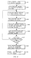
- Figure 4 is a flow chart for explaining the operation of rough classification device 34.
- step S41 DSP 30 writes a control word to control register 42a in RAM control 42.
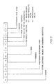
- Bit assignments for the control word are shown in Figure 5.
- bit 15 is a start bit for instructing the rough classification device 34 to begin its classification and/or sorting tasks.
- Bit 14 is a tag bit used to instruct the device whether to store the distance values from sorter 41 in data RAM 44 or to store the candidate identities from sorter 41.
- Bit 13 indicates whether to sort in ascending or descending order.
- Bits 9 and 10 indicate whether the rough classification device simply calculates distance values without sorting, simply sorts data in data RAM 44, or both calculates distance values and sorts the calculated distance values.
- Bits 7 and 8 specify which one of the distance functions will be utilized by classifier 40, namely the above-mentioned Mahalanobis distance function, the mean absolute value distance function or the mean square value distance function.
- Bit 6 indicates whether to store the top 100 or the top 52 candidates in data RAM 44.
- Bit 5 indicates where to begin accessing data in dictionary ROMs 35a and 35b. If bit 5 is set to 1, the dictionary ROMs are accessed from the beginning thereof; on the other hand, if bit 5 is set to 0 then the dictionary ROMs are accessed beginning with the last access address.
- Bits 0, 1 and 2 indicate the dictionary ROM mode, that is, the number of dictionary ROMs provided in the device and the interleave coordination for these dictionary ROMs.
- step S42 DSP 30 puts the feature vector for the unknown pattern onto recognition bus 29 and RAM control 42 stores the feature vector in sequential locations in data RAM 44.
- step S43 sorter memory 41 is initialized to a predetermined value in preparation for sorting operations.
- the predetermined value may be the maximum expected distance value or the minimum expected distance value in accordance with whether an ascending or descending sort is desired.
- other initialization values may be used.
- step S44 in accordance with start bit 15, data RAM 44 provides the feature vector of the unknown pattern to classifier 40.
- Dictionary control 39 then accesses dictionary ROMs 35a and 35b in the sequence designated by ROM start address bit 5 and causes the feature vectors corresponding to the candidate patterns in the dictionary ROMs also to be provided to classifier 40.
- the dictionary feature vector W In case of the Mahalanobis function, the dictionary feature vector W must be pre-processed as shown above for equation (1).
- a separate dictionary may be provided solely for use when the Mahalanobis function is selected. The separate dictionary would contain feature vectors that are pre-processed according to equation (1) and that can be used directly with the unknown feature vector.
- step S45 classifier 40 calculates the distance value between the unknown feature vector and the candidate feature vector.
- the distance function used to calculate the distance value is selected in accordance with bits 7 and 8 of the control word stored in control register 42a.
- step S46 the newly calculated distance value is provided to sorter 41.
- Sorter 41 sorts the new distance value into previously-calculated distance values as described in the aforementioned U.S. application Serial No. 07/554,384. The sort is conducted utilizing the top 100 or the top 52 candidates in accordance with bit 6 of the control word stored in control register 42a, and is conducted in ascending or descending order in accordance with bit 13.
- step S47 control returns to step S43.
- step S48 in which the sorted distance values together with the sorted candidate identities are provided to data RAM 44.
- RAM 44 stores either the distance values or the candidate identities in accordance with bit 14 of the control word stored in control register 42a. The data are written in sequential locations of data RAM 44 and overwrite the data for the unknown feature vector that was stored in step S42.
- step S49 the rough classification device 34 raises an NPO flag (see Figure 3) to signal DSP 30 that new proposed output is ready.
- Digital signal processor 30 reads data RAM 44 via recognition bus 29 and processes the sorted data as described in more detail below.
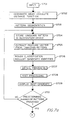
- Figure 6 is a flow chart for explaining the operation of the pattern recognition apparatus shown in Figures 1, 2 and 3.
- the process steps illustrated in Figure 6 are stored in the form of computer programs in an unshown memory for host CPU 10, in PROM 22 for microprocessor 21 and in PROM 31 for DSP 30, and executed by host CPU 10, microprocessor 21, and digital signal processor 30, respectively, as will be evident from the following description.
- one of plural different recognition modes for recognizing an unknown pattern are selected in accordance with the characteristics of the unknown pattern.
- the discriminant function by which the pattern is recognized is selected in accordance with the characteristics of the pattern.
- the image characteristics include the image quality, the font and the size of the type face.
- step S601 image data is input from input device 11 into host CPU 10.
- Host CPU 10 stores the image data in image memory 12.
- step S602 the discriminant function by which the unknown pattern is to be recognized is manually designated via operator interface on host CPU 10 and transferred to character recognition device 14 on interface 13. The designation is made in dependence upon the image quality, the type of font, and the size of the type face.
- Table 1 shows discriminant functions that have been found to provide reliable character recognition results based on image quality, font type and size of type face.
- the mean absolute distance discriminant function should be designated in step S602.
- the Mahalanobis discriminant function should be designated in step S602.
- the particular discriminant function that should be designated in step S602 is manually selected via operator interface on host CPU 10 in accordance with the image quality, the font type and the size of the type face as shown in Table 1.
- the entry "MSD/MAD" indicates that both the mean square distance function and the mean absolute distance function provide reliable character recognition results, and either discriminant function may be designated in step S602.
- step S603 host CPU 10 segments the image into individual patterns and sequentially transfers the segmented pattern to character recognition device 14 via interface 13.
- step S604 character recognition device 14 accepts an unknown pattern via SCSI controller 26 and stores the unknown pattern in buffer memory 24.
- Buffer memory 24 is controlled by microprocessor 21 such that it stores patterns transmitted from host CPU 10 so as to provide a continuous stream of patterns to recognition bus 29.
- the interface between the communication bus 20 and recognition bus 29 is provided by internal buffer memory 27.
- step S605 the unknown pattern, which has been transmitted to the recognition bus 29 via internal buffer memory 27, is transmitted by digital signal processor 30 to feature extraction device 32.
- feature extraction device 32 determines a feature vector from the unknown pattern in which each component of the vector represents a different feature of the unknown pattern such as stroke position, direction, length, and so forth. Typically, up to about 200 different features are extracted for each unknown pattern.
- step S606 digital signal processor 30 writes a control word to the control register of rough classification device 34 that commands the rough classification device to return sorted candidate identities rather than sorted distance values (i.e., bit 14 is set to "zero").
- a subset of the feature vector determined in step S605 is transmitted to the data RAM 44 in the rough classification device.
- the start bit is set in the rough classification device to command the rough classification device to compare the feature vector of the unknown pattern to the feature vectors stored in dictionary ROMs 35a and 35b as described above with respect to Figure 4.
- step S607 upon detection of the NPO signal from rough classification device 34, the sorted candidate identities are subjected to detail processing whereby the full feature vector extracted in step S605 is compared to full feature vectors stored in detailed dictionary ROM 36.
- other discriminant functions such as a pseudo-bayesian discriminant function, may be used in addition to or in place of the Mahalanobis distance function or the mean square value distance function or the mean absolute value distance function.
- the pseudo-bayesian discriminant function method the first k elements of the feature vector are used for distance calculation. Then, by assuming that the mean value of the remaining elements is h, and by using h instead of the remaining elements, distance is calculated.
- Such a method permits distance calculation for large feature vectors in short amounts of time.
- the rough classification performed in step S606 there is no need to calculate distance functions for each of the entries in detailed dictionary ROM 36; rather, only the candidate identities returned in the rough classification step need be examined.
- step S607 The candidate identities that are determined to be the best for the unknown pattern in detail processing step S607 are transmitted from the recognition bus 29 to the communication bus 20 via internal buffer memory 27, and thence to host CPU 10 via buffer memory 24 and SCSI controller 26 over interface 13.
- host CPU 10 performs post-processing on the candidate identities to assign an identity to the unknown pattern.
- post-processing may consist of spell checking, syntax checking, context checking (for example, rejecting letters that are embedded in numbers or vice versa), and so on.
- the identity assigned to the unknown pattern is stored in character memory 15 and displayed on display 16 (step S609).
- step S610 it is determined whether there are additional unknown patterns for which identities are required. If there are additional patterns, then flow returns to step S604; on the other hand, if there are no additional patterns then operation terminates.
- Figure 7 is a flow chart showing a second operational mode for the pattern recognition device shown in Figures 1, 2 and 3, and in which the discriminant function used for pattern recognition is selected in accordance with image characteristics.
- the image characteristics are inferred based on the number of rejects (that is, the number of unrecognizable characters) encountered during pattern recognition.
- step S701 image data is input from input device 11 into host CPU 10 which stores the image data in image memory 12.
- step S702 the mean absolute distance function is designated in preparation for character recognition.
- Steps S703 through S708 are substantially similar to steps S603 through step S609, respectively, and a detailed description thereof is omitted.
- step S709 the identity assigned to the unknown pattern is stored in character memory 15 by host CPU 10.
- step S710 host CPU 10 determines whether a predetermined number of patterns have been subjected to pattern recognition.
- the number of predetermined characters corresponds to about one page of character information. If a predetermined number of patterns have not yet been processed, then flow returns to step S704 until a predetermined number of patterns have been subjected to pattern recognition.
- step S711 CPU 10 counts the number of rejects encountered during pattern recognition.
- a reject may be identified by, for example, the techniques described in the above-referenced U.S. application entitled “Method And Apparatus For Pattern Recognition".
- step S712 if the number of rejects are greater than a predetermined level, then it is considered that the image characteristics are such that the mean absolute distance function is not suitable for pattern recognition. Accordingly, flow advances to step S713 in which the mean square distance function is designated and pattern recognition is repeated for the predetermined number of patterns that were processed in steps S703 through S708 (step S714).
- step S715 the number of rejects are again counted and in step S716, if the number of rejects are greater than a predetermined number then it is then considered that the image quality is such that the mean square distance function is not suitable for pattern recognition. Accordingly, the Mahalanobis distance function is designated for pattern recognition (step S717), and pattern recognition is repeated for the predetermined number of patterns that were processed in step S714 (step S718).
- step S719 When the number of rejects is not greater than a predetermined number (or after the Mahalanobis distance function has been designated), flow advances to step S719 where it is determined if there are additional unknown patterns for which identities are required. If there are additional patterns, then flow advances to step S720 in which the pattern recognition process is continued with the discriminant function previously designated, that is, the discriminant function designated in step S702, S713, or step S717. On the other hand, if there are no additional patterns, then operation terminates.
- Figure 8 is a block diagram showing a modification to the pattern recognition device shown in Figure 2.
- rough classification device 34 is provided with two different sets of dictionary ROMs.
- Dictionary ROM set 135a and 135b provides a dictionary of feature vectors that are suitable for images of good quality
- dictionary ROM set 235a and 235b provides dictionary vectors that are suitable when image quality is degraded.
- Which one of the two dictionary ROM sets used during pattern recognition is controlled in accordance with bits 2 through 0 in the control word shown in Figure 5 and stored in control register 42a, and these bits are set as described more fully below.
- Figure 9 is a flow chart for explaining operation of the Figure 8 apparatus.
- step S901 image data is input from input device 11 into host CPU 10 which stores the image data in image memory 12.
- step S902 a control word is written to control register 42a so as to designate dictionary set 135a and 135b, namely dictionary ROMs containing feature vectors suitable for recognizing good quality images.
- step S903 pattern recognition is performed, for example, as explained above with reference to steps S603 through S609, but by reference to dictionary ROM set 135a and 135b, as described above.
- step S904 it is determined whether recognition has been performed for a predetermined number of patterns, for example, a number of characters corresponding to a page of character information. If not, flow returns to step S903 until a predetermined number of characters have been recognition-processed.
- step S905 CPU 10 counts the number of reject characters (that is, the number of patterns which are unrecognizable) which have been encountered.
- reject processing can be conducted in accordance with the aforementioned application entitled Method And Apparatus For Pattern Recognition filed on even date herewith by the present inventor.
- step S906 if the number of rejects are greater than the predetermined number, then flow advances to step S907 in which dictionary ROM set 235a and 235b are designated. Specifically, if the number of rejects are greater than a predetermined number, then it is considered that the characteristics of the pattern to be recognized are such that dictionary ROMs for good quality images are unsuitable and that the image characteristics must correspond to that of a degraded image.
- step S908 recognition is repeated for the predetermined number of characters whereupon flow advances to step S909.
- step S909 it is determined whether there are additional characters that require character recognition. If there are additional characters, then flow advances to step S910 where character recognition is performed using the dictionary ROM set previously designated. If there are no additional characters for processing, then flow terminates.
- Figure 10 illustrates a further embodiment of a pattern recognition apparatus according to the present invention.
- components having functions similar to those described above have been assigned the same reference numerals.
- a host CPU 10 obtains image data from an image data input device 11 and stores the image data in image memory 12.
- the image data in image memory is segmented by CPU 10 into individual unknown patterns which are transmitted to character recognition apparatus 14 via interface 13.
- Character recognition device 14 performs feature extraction to obtain a feature vector for the unknown pattern, performs rough classification based on the feature vector, and detailed classification based on the results of the rough classification, all as described hereinabove in connection with Figures 1 to 9.
- the identities of the candidates from detail processing are transmitted back to host CPU 10 via bus 13, whereupon host CPU performs post-processing to assign an identity to the unknown pattern.
- the identities assigned to the unknown patterns are transmitted via bus 51 to local area network bus 52.
- Local area network bus 52 is accessed by plural stand alone computers 53 whereby each of the stand alone computers can avail itself of the pattern recognition capabilities of the recognition apparatus.
- FIG 11 illustrates another embodiment of the pattern recognition apparatus according to the present invention.
- elements having functions and structures similar to those described above have been assigned the same reference numerals.
- local area network bus 52 is provided with an image data input device 11, a character recognition device 14 and plural stand alone computers 53.
- each of stand alone computers 53 is able to access the image data input capabilities of image data input device 11 and to channel the image data so received to character recognition device 14 so as to obtain the identities of candidates for unknown patterns.
- This structure eliminates the necessity of providing a host CPU and an image memory; the processes performed by host CPU 10 and image memory 12 in the previous embodiments can be performed by the stand alone computers 53.
- Figures 12 and 13 are views for explaining operation of any of the foregoing embodiments in the case where the image data input by input device 11 contains image data representing characters mixed with image data representing images.
- image data typically contains areas 61 representing images of characters or text data as well as areas 62 representing non-character image data, for example, graphs, pictures, charts and the like.
- areas 61 representing images of characters or text data
- areas 62 representing non-character image data, for example, graphs, pictures, charts and the like.
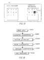
- FIG 13 is a flow chart illustrating this mode of operation.
- image data is input.
- the image data is inspected to identify individual blocks of information and each individual block of information is discriminated as to whether the block contains character information or non-character information (step S1302).
- Such discrimination is known in the art, for example, as described in U.S. Patents 4,701,807 and 4,729,035.
- Step S1303 determines whether a character block has been discriminated in step S1302. If a character block has not been discriminated then in step S1304 the image data is stored without processing. On the other hand, if a character block has been discriminated, then in step S1305 character recognition processing is performed in accordance with any of the techniques described above. In step S1306 the identity of recognized characters are stored.
- step S1307 the stored data, whether image or character, is output.
- the stored data may be output via a modem to a telephone interface.
- character data is output in code form, for example, ASCII code
- image data is output in image form, for example, in accordance with the CCITT standards for G3 facsimile transmission.
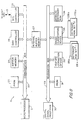
- Figures 14 and 15 are views for explaining a further embodiment of the invention in which it is possible to preview the results of character recognition for word-processed text.
- Previewing provides assurance that the original word-processed text file can be recovered, through pattern recognition, from an image of the word-processed text.
- previewing ensures that the image received at the remote location can be subjected to character recognition for the purposes of recovering the original word-processed text file.
- a text file 70 is printed out at 71 and facsimile-transmitted at 72.
- the need for a printout is avoided and as shown by the dotted arrow the text file 70 is converted to a print image at 76 and facsimile-transmitted at 72.
- the image received at facsimile reception 73 is subjected to character recognition at 74 to create a text file at 75.
- Character recognition 74 may be performed according to any of the above-described embodiments of pattern recognition systems.
- text file 75 contains the same information as text file 70
- the results of image conversion, transmission and pattern recognition are previewed.
- the text file 70 is subjected to electronic image conversion 76.
- the image so created reflects the various fonts and type size that will be used at printout 71.
- the image converted at 76 is subjected to character recognition at 77 to form a text file at 78.
- the original text file 70 is displayed at 79, and the pattern-recognized text file 78 is displayed at 80.
- the displays may be side by side as shown in Figure 15 which depicts the appearance of data on the display.
- the text files are compared and discrepancies between the two text files are noted. Any such discrepancies, such as those indicated in reverse graphics at 90, indicate that the transmission process depicted at 71, 72, 73, 74 and 75 will not successfully recover the text file at 75. Accordingly, adjustments may be made in the text file, or the text file may be printed out using a different font, style, size, etc. Such modifications are made as necessary until text file 78 is identical to text file 70. At that point, it can be assured that the transmission process 72 will result in text file 78 that is identical to text file 70.
Description
- The present invention relates to a method of pattern recognition and an apparatus for recognizing patterns. In particular, the present invention relates to a method and apparatus which adapts to the characteristics of an unknown pattern, wherein said pattern is required to be recognized.
- In a pattern recognition system, an unknown pattern, for example, a pattern derived from an image scanner or received by facsimile transmission, is analyzed to determine the identity of the pattern. Figure 16 illustrates a typical pattern recognition process, which identifies individual characters in an image containing a plurality of such characters.
- As shown in Figure 16, an image, derived for example, from an image scanner, is input in step S1601 and the individual characters in the image are segmented in step S1602. Steps S1601 and S1602 are typically performed by a general purpose host computer which then transmits the characters segmented in step S1602 to a dedicated optical character recognition device. In step S1603, the optical character recognition device subjects the segmented characters to feature extraction whereby a feature vector is derived for the unknown pattern. The feature vector represents various features concerning the pattern such as stroke position, direction, length, and so forth. Then, in rough classification step 1604, the feature vector for the unknown pattern is then compared to a dictionary which contains plural feature vectors for standard patterns. Specifically, the feature vector for the unknown pattern is compared with each feature vector in the standard pattern dictionary and a distance value is calculated representing the mathematical distance between the feature vector for the unknown pattern and the feature vector for the standard pattern. The distance values are sorted and the best candidates, for example, the 52 candidates that are nearest to the feature vector for the unknown pattern, are selected. In step S1605, the best candidates are subjected to detailed classification. In detail classification, additional discriminant functions, for example a pseudo-bayesian discriminant function, are employed to select the best candidate or candidates from among those determined in the rough classification step. The best candidate or candidates for the unknown pattern are then transmitted back to the general purpose host computer where they are subjected to post processing in step S1606. Post processing typically entails processing such as spell-checking, context checking and syntax processing and results in selection of one candidate for the unknown pattern.
- While the process depicted in Figure 16 permits identification of unknown patterns with high accuracy, there still remains a problem. Specifically, patterns to be recognized usually do not have uniform quality or characteristics, and it is not always possible to recognize unknown patterns that have characteristics other than those that are expected.
- It is therefore a concern of the present invention to provide a character recognition system which adapts to the characteristics of the pattern to be recognized.
- Japanese Patent Abstract No. JP-A-59045585 discloses a character recognizing device in which in order to improve scanning efficiency dictionary data stored in a main dictionary memory is replaced with dictionary data stored in an auxiliary dictionary memory when a predetermined number of reject characters have been counted by a counter.
- An article entitled "Specimen Identification Device" in IBM Technical Disclosure Bulletin in
Volume 6, No. 1, June 1963, New York, page 111 by J. Reines et al discloses an automatic font selection algorithm for optimising character recognition in which a variance of distances between centers of segmented characters in one character row and an average width and height of the characters are detected to select a decision tree of various fonts which is used for recognizing the characters in the character row. - It will be appreciated that neither of these prior documents is concerned with selecting between various modes of pattern recognition. In the first document the recognition mode is always the same and only the dictionary is changed. The second document carries out an equivalent process by changing fonts.
- In one aspect of the present invention provides a pattern recognition apparatus as set out in claim 1.
- In another aspect the present invention provides a method of pattern recognition as set out in claim 11.
- This brief summary of the invention has been provided so that the nature of the invention may be understood quickly. A more complete understanding of the invention may be obtained by reference to the following detailed description in connection with the appended drawings.
- Figure 1 is an overall block diagram of a pattern recognition apparatus according to the present invention;
- Figure 2 is a detailed block diagram of the optical character recognition device depicted in Figure 1;
- Figure 3 is a detailed block diagram of the rough classification device depicted in Figure 2;
- Figure 4 is a flow chart for describing the operation of the rough classifier shown in Figure 3;
- Figure 5 is a diagram for explaining a control word used in the rough classifier of Figure 3;
- Figures 6 and 7 are flow charts for explaining pattern recognition according to the invention;
- Figure 8 is a modification of the Figure 2 character recognition device used for explaining another embodiment of the invention;
- Figure 9 is a flow chart for explaining the operation of the Figure 8 embodiment;
- Figures 10 and 11 are block diagrams for showing alternative embodiments of a pattern recognition apparatus according to the invention;
- Figure 12, comprising Figures 12(a) and 12(b), are views for explaining examples of pattern recognition according to the present invention;
- Figure 13 is a flow chart used for explaining pattern recognition according to Figure 12;
- Figure 14 is a functional block diagram for explaining another pattern recognition system according to the invention;
- Figure 15 is a view for showing a pattern recognition result according to the Figure 14 system; and
- Figure 16 is a flow chart for explaining a known pattern recognition process.
-
- Figure 1 is an overall block diagram of a pattern recognition apparatus according to the present invention.
- As shown in Figure 1, the pattern recognition system includes a
host CPU 10 such as an EZPS3500 programmable microprocessor, an image data input device 11 such as an image scanner or facsimile reception unit, animage memory 12 for storing image data input by the input device, acharacter recognition device 14 for recognizing unknown patterns transferred byhost CPU 10 overSCSI interface 13 and transferring candidates for the unknown pattern back to the host CPU overinterface 13, acharacter memory 15 for storing the candidates transmitted from the character recognition device, and adisplay 16 for displaying the pattern recognition results. - Figure 2 is a detailed block diagram of
character recognition device 14. - As shown in Figure 2,
character recognition device 14 is comprised by a communication part and a recognition part. The communication part includes acommunication bus 20 to which are connected amicroprocessor 21 such as a 68000 programmable microprocessor, a programmable read only memory ("PROM") 22 for storing process steps for execution bymicroprocessor 21, abuffer memory 24 for buffering communication to and fromhost CPU 10, aDMA controller 25 for controlling direct memory access withhost CPU 10, anSCSI controller 26 for communication withhost CPU 10 overinterface 13, and aninternal buffer memory 27 for providing internal buffering between the communication part and the recognition part. The recognition part includes arecognition bus 29 to which are connected the aforementionedinternal buffer memory 27 as well as a digital signal processor ("DSP") 30 such as a TMS320C25 Texas Instruments digital signal processor, aPROM 31 for storing process steps to be executed byDSP 30, a feature extraction device for extracting a feature vector from an unknown pattern, a rough classification device 34 for providing plural candidates selected fromdictionary ROMs detailed dictionary ROM 36 for providing detailed dictionary data by which the rough classification candidates are narrowed and provided to hostCPU 10 for post processing. - Figure 3 is a detailed block diagram of rough classification device 34.
- As shown in Figure 3, rough classification device 34 includes
main control logic 37 for controlling the various components within the rough classification device. In particular,main control logic 37 controlsdictionary control 39,classifier 40,sorter 41 andRAM control 42 which, in turn, controlsdata RAM 44.Main control logic 37 also asserts a "new proposed output" flag ("NPO") toDSP 30 when a new output is available. - In more detail,
dictionary control 39 provides control fordictionary ROMs dictionary control 39 provides aninterleave control signal 45 and adictionary address signal 46. These signals permitreading dictionary ROMs -
Classifier 40 includes two arithmetic units (one for each dictionary ROM) for calculating the distance between a dictionary feature vector and the feature vector for the unknown pattern. Under control frommain control logic 37,classifier 40 calculates the distance in accordance with one of three distance functions, namely the Mahalanobis distance function, the mean absolute value distance function, and the mean square distance function. In more detail, the Mahalanobis distance function calculates the dot product of the feature vector X of the unknown pattern and the feature vector W from the dictionary ROM as follows:where kmax is the dimensionality of the feature vector, Z = -2C-1W (C is average covariance matrix of the dictionary vectors), X0 = 1, and W0 = WTC-1W.
- The mean absolute distance function sums all of the absolute distances between the feature vector of the unknown pattern and the feature vector from the dictionary ROM as follows:

- The mean square distance function sums the square of the distance between the feature vector of the unknown pattern and the feature vector from the dictionary ROM as follows:

- The distance value so calculated, together with the identity of the candidate that corresponds to the distance value, is provided to sorter 41.
Sorter 41 sorts the distance values provided fromclassifier 40 into ascending or descending order in accordance with a control signal frommain control logic 37. A sorter suitable for use assorter 41 is described in detail in application Serial No. 07/554,384 filed July 19, 1990 by the inventor of the present application. The contents of application Serial No. 07/554,384 are hereby incorporated by reference as if set forth in full herein. - When
classifier 40 has processed each feature vector indictionary ROMs main control logic 37 causes sorter 41 to transmit sorted distance values and corresponding candidate identities todata ROM 44. Under the control ofRAM 42 andmain control logic 37,data RAM 44 stores the sorted distance values and the corresponding candidate identities in sequential storage locations. To conserve storage space indata RAM 44, it is preferable for the data RAM to store only one of the distance values or the candidate identities, and this election is made in accordance with control fromRAM control 42. - Figure 4 is a flow chart for explaining the operation of rough classification device 34.
- In step S41,
DSP 30 writes a control word to controlregister 42a inRAM control 42. Bit assignments for the control word are shown in Figure 5. As shown there,bit 15 is a start bit for instructing the rough classification device 34 to begin its classification and/or sorting tasks.Bit 14 is a tag bit used to instruct the device whether to store the distance values fromsorter 41 indata RAM 44 or to store the candidate identities fromsorter 41.Bit 13 indicates whether to sort in ascending or descending order.Bits data RAM 44, or both calculates distance values and sorts the calculated distance values.Bits classifier 40, namely the above-mentioned Mahalanobis distance function, the mean absolute value distance function or the mean square value distance function.Bit 6 indicates whether to store the top 100 or the top 52 candidates indata RAM 44.Bit 5 indicates where to begin accessing data indictionary ROMs bit 5 is set to 1, the dictionary ROMs are accessed from the beginning thereof; on the other hand, ifbit 5 is set to 0 then the dictionary ROMs are accessed beginning with the last access address.Bits 0, 1 and 2 indicate the dictionary ROM mode, that is, the number of dictionary ROMs provided in the device and the interleave coordination for these dictionary ROMs. - Reverting to Figure 4, in step S42,
DSP 30 puts the feature vector for the unknown pattern ontorecognition bus 29 andRAM control 42 stores the feature vector in sequential locations indata RAM 44. In step S43,sorter memory 41 is initialized to a predetermined value in preparation for sorting operations. As described in Serial No. 07/554,384, the predetermined value may be the maximum expected distance value or the minimum expected distance value in accordance with whether an ascending or descending sort is desired. As described more fully in connection with the application entitled "Method And Apparatus For Pattern Recognition" filed on even date herewith by the same inventor herein, other initialization values may be used. - In step S44, in accordance with
start bit 15,data RAM 44 provides the feature vector of the unknown pattern toclassifier 40.Dictionary control 39 then accessesdictionary ROMs start address bit 5 and causes the feature vectors corresponding to the candidate patterns in the dictionary ROMs also to be provided toclassifier 40. In case of the Mahalanobis function, the dictionary feature vector W must be pre-processed as shown above for equation (1). Alternatively, though not shown, a separate dictionary may be provided solely for use when the Mahalanobis function is selected. The separate dictionary would contain feature vectors that are pre-processed according to equation (1) and that can be used directly with the unknown feature vector. - In step S45,
classifier 40 calculates the distance value between the unknown feature vector and the candidate feature vector. The distance function used to calculate the distance value is selected in accordance withbits control register 42a. In step S46 the newly calculated distance value is provided tosorter 41.Sorter 41 sorts the new distance value into previously-calculated distance values as described in the aforementioned U.S. application Serial No. 07/554,384. The sort is conducted utilizing the top 100 or the top 52 candidates in accordance withbit 6 of the control word stored incontrol register 42a, and is conducted in ascending or descending order in accordance withbit 13. - If there are additional feature vectors stored in
dictionary ROMs data RAM 44.RAM 44 stores either the distance values or the candidate identities in accordance withbit 14 of the control word stored incontrol register 42a. The data are written in sequential locations ofdata RAM 44 and overwrite the data for the unknown feature vector that was stored in step S42. - In step S49 the rough classification device 34 raises an NPO flag (see Figure 3) to signal
DSP 30 that new proposed output is ready.Digital signal processor 30 readsdata RAM 44 viarecognition bus 29 and processes the sorted data as described in more detail below. - Figure 6 is a flow chart for explaining the operation of the pattern recognition apparatus shown in Figures 1, 2 and 3. The process steps illustrated in Figure 6 are stored in the form of computer programs in an unshown memory for
host CPU 10, inPROM 22 formicroprocessor 21 and inPROM 31 forDSP 30, and executed byhost CPU 10,microprocessor 21, anddigital signal processor 30, respectively, as will be evident from the following description. - In the operation depicted in Figure 6, one of plural different recognition modes for recognizing an unknown pattern are selected in accordance with the characteristics of the unknown pattern. In particular, the discriminant function by which the pattern is recognized is selected in accordance with the characteristics of the pattern. In the case where the pattern to be recognized is a character pattern, the image characteristics include the image quality, the font and the size of the type face.
- Thus, in step S601, image data is input from input device 11 into
host CPU 10.Host CPU 10 stores the image data inimage memory 12. - In step S602, the discriminant function by which the unknown pattern is to be recognized is manually designated via operator interface on
host CPU 10 and transferred tocharacter recognition device 14 oninterface 13. The designation is made in dependence upon the image quality, the type of font, and the size of the type face. - Table 1 shows discriminant functions that have been found to provide reliable character recognition results based on image quality, font type and size of type face. Thus, as shown in Table 1, for good images of large size typeface, the mean absolute distance discriminant function should be designated in step S602. On the other hand, for degraded images of small size type face, the Mahalanobis discriminant function should be designated in step S602. Intermediate these two extremes, the particular discriminant function that should be designated in step S602 is manually selected via operator interface on
host CPU 10 in accordance with the image quality, the font type and the size of the type face as shown in Table 1. In situations such as that shown for 9-point standard font characters of good image quality, the entry "MSD/MAD" indicates that both the mean square distance function and the mean absolute distance function provide reliable character recognition results, and either discriminant function may be designated in step S602. - In step S603,
host CPU 10 segments the image into individual patterns and sequentially transfers the segmented pattern tocharacter recognition device 14 viainterface 13. - In step S604,
character recognition device 14 accepts an unknown pattern viaSCSI controller 26 and stores the unknown pattern inbuffer memory 24.Buffer memory 24 is controlled bymicroprocessor 21 such that it stores patterns transmitted fromhost CPU 10 so as to provide a continuous stream of patterns torecognition bus 29. The interfacebetween the
communication bus 20 andrecognition bus 29 is provided byinternal buffer memory 27. - In step S605, the unknown pattern, which has been transmitted to the
recognition bus 29 viainternal buffer memory 27, is transmitted bydigital signal processor 30 to featureextraction device 32. As is known,feature extraction device 32 determines a feature vector from the unknown pattern in which each component of the vector represents a different feature of the unknown pattern such as stroke position, direction, length, and so forth. Typically, up to about 200 different features are extracted for each unknown pattern. - In step S606,
digital signal processor 30 writes a control word to the control register of rough classification device 34 that commands the rough classification device to return sorted candidate identities rather than sorted distance values (i.e.,bit 14 is set to "zero"). A subset of the feature vector determined in step S605 is transmitted to thedata RAM 44 in the rough classification device. The start bit is set in the rough classification device to command the rough classification device to compare the feature vector of the unknown pattern to the feature vectors stored indictionary ROMs - In step S607, upon detection of the NPO signal from rough classification device 34, the sorted candidate identities are subjected to detail processing whereby the full feature vector extracted in step S605 is compared to full feature vectors stored in
detailed dictionary ROM 36. For this detailed processing, other discriminant functions, such as a pseudo-bayesian discriminant function, may be used in addition to or in place of the Mahalanobis distance function or the mean square value distance function or the mean absolute value distance function. In the pseudo-bayesian discriminant function method, the first k elements of the feature vector are used for distance calculation. Then, by assuming that the mean value of the remaining elements is h, and by using h instead of the remaining elements, distance is calculated. Such a method permits distance calculation for large feature vectors in short amounts of time. Moreover, because of the rough classification performed in step S606 there is no need to calculate distance functions for each of the entries indetailed dictionary ROM 36; rather, only the candidate identities returned in the rough classification step need be examined. - The candidate identities that are determined to be the best for the unknown pattern in detail processing step S607 are transmitted from the
recognition bus 29 to thecommunication bus 20 viainternal buffer memory 27, and thence to hostCPU 10 viabuffer memory 24 andSCSI controller 26 overinterface 13. In step S608,host CPU 10 performs post-processing on the candidate identities to assign an identity to the unknown pattern. In particular, post-processing may consist of spell checking, syntax checking, context checking (for example, rejecting letters that are embedded in numbers or vice versa), and so on. The identity assigned to the unknown pattern is stored incharacter memory 15 and displayed on display 16 (step S609). - In step S610 it is determined whether there are additional unknown patterns for which identities are required. If there are additional patterns, then flow returns to step S604; on the other hand, if there are no additional patterns then operation terminates.
- Figure 7 is a flow chart showing a second operational mode for the pattern recognition device shown in Figures 1, 2 and 3, and in which the discriminant function used for pattern recognition is selected in accordance with image characteristics. In Figure 7, the image characteristics are inferred based on the number of rejects (that is, the number of unrecognizable characters) encountered during pattern recognition.
- Thus, in step S701, image data is input from input device 11 into
host CPU 10 which stores the image data inimage memory 12. In step S702, the mean absolute distance function is designated in preparation for character recognition. - Steps S703 through S708 are substantially similar to steps S603 through step S609, respectively, and a detailed description thereof is omitted. In step S709, the identity assigned to the unknown pattern is stored in
character memory 15 byhost CPU 10. - In step S710,
host CPU 10 determines whether a predetermined number of patterns have been subjected to pattern recognition. In the case of character recognition, the number of predetermined characters corresponds to about one page of character information. If a predetermined number of patterns have not yet been processed, then flow returns to step S704 until a predetermined number of patterns have been subjected to pattern recognition. - When a predetermined number of patterns have been subjected to pattern recognition, then flow advances to step S711 in which
CPU 10 counts the number of rejects encountered during pattern recognition. A reject may be identified by, for example, the techniques described in the above-referenced U.S. application entitled "Method And Apparatus For Pattern Recognition". - In step S712, if the number of rejects are greater than a predetermined level, then it is considered that the image characteristics are such that the mean absolute distance function is not suitable for pattern recognition. Accordingly, flow advances to step S713 in which the mean square distance function is designated and pattern recognition is repeated for the predetermined number of patterns that were processed in steps S703 through S708 (step S714).
- In step S715, the number of rejects are again counted and in step S716, if the number of rejects are greater than a predetermined number then it is then considered that the image quality is such that the mean square distance function is not suitable for pattern recognition. Accordingly, the Mahalanobis distance function is designated for pattern recognition (step S717), and pattern recognition is repeated for the predetermined number of patterns that were processed in step S714 (step S718).
- When the number of rejects is not greater than a predetermined number (or after the Mahalanobis distance function has been designated), flow advances to step S719 where it is determined if there are additional unknown patterns for which identities are required. If there are additional patterns, then flow advances to step S720 in which the pattern recognition process is continued with the discriminant function previously designated, that is, the discriminant function designated in step S702, S713, or step S717. On the other hand, if there are no additional patterns, then operation terminates.
- Figure 8 is a block diagram showing a modification to the pattern recognition device shown in Figure 2. In the Figure 8 block diagram, rough classification device 34 is provided with two different sets of dictionary ROMs. Dictionary ROM set 135a and 135b provides a dictionary of feature vectors that are suitable for images of good quality, whereas dictionary ROM set 235a and 235b provides dictionary vectors that are suitable when image quality is degraded. Which one of the two dictionary ROM sets used during pattern recognition is controlled in accordance with
bits 2 through 0 in the control word shown in Figure 5 and stored incontrol register 42a, and these bits are set as described more fully below. - Figure 9 is a flow chart for explaining operation of the Figure 8 apparatus.
- In step S901, image data is input from input device 11 into
host CPU 10 which stores the image data inimage memory 12. In step S902, a control word is written to controlregister 42a so as to designate dictionary set 135a and 135b, namely dictionary ROMs containing feature vectors suitable for recognizing good quality images. - In step S903, pattern recognition is performed, for example, as explained above with reference to steps S603 through S609, but by reference to
dictionary ROM set 135a and 135b, as described above. - In step S904, it is determined whether recognition has been performed for a predetermined number of patterns, for example, a number of characters corresponding to a page of character information. If not, flow returns to step S903 until a predetermined number of characters have been recognition-processed.
- When a predetermined number of characters have been recognition-processed, flow advances to step S905 where
CPU 10 counts the number of reject characters (that is, the number of patterns which are unrecognizable) which have been encountered. Reject processing can be conducted in accordance with the aforementioned application entitled Method And Apparatus For Pattern Recognition filed on even date herewith by the present inventor. - In step S906, if the number of rejects are greater than the predetermined number, then flow advances to step S907 in which dictionary ROM set 235a and 235b are designated. Specifically, if the number of rejects are greater than a predetermined number, then it is considered that the characteristics of the pattern to be recognized are such that dictionary ROMs for good quality images are unsuitable and that the image characteristics must correspond to that of a degraded image. In step S908, recognition is repeated for the predetermined number of characters whereupon flow advances to step S909. In step S909, it is determined whether there are additional characters that require character recognition. If there are additional characters, then flow advances to step S910 where character recognition is performed using the dictionary ROM set previously designated. If there are no additional characters for processing, then flow terminates.
- Figure 10 illustrates a further embodiment of a pattern recognition apparatus according to the present invention. In Figure 10, components having functions similar to those described above have been assigned the same reference numerals.
- In the pattern recognition apparatus of Figure 10, a
host CPU 10 obtains image data from an image data input device 11 and stores the image data inimage memory 12. The image data in image memory is segmented byCPU 10 into individual unknown patterns which are transmitted tocharacter recognition apparatus 14 viainterface 13.Character recognition device 14 performs feature extraction to obtain a feature vector for the unknown pattern, performs rough classification based on the feature vector, and detailed classification based on the results of the rough classification, all as described hereinabove in connection with Figures 1 to 9. The identities of the candidates from detail processing are transmitted back tohost CPU 10 viabus 13, whereupon host CPU performs post-processing to assign an identity to the unknown pattern. - The identities assigned to the unknown patterns are transmitted via
bus 51 to localarea network bus 52. Localarea network bus 52 is accessed by plural standalone computers 53 whereby each of the stand alone computers can avail itself of the pattern recognition capabilities of the recognition apparatus. - The operation of the embodiment shown in Figure 10 is identical in all other respects to the operation of the embodiments above.
- Figure 11 illustrates another embodiment of the pattern recognition apparatus according to the present invention. In Figure 11, elements having functions and structures similar to those described above have been assigned the same reference numerals.
- As shown in Figure 11, local
area network bus 52 is provided with an image data input device 11, acharacter recognition device 14 and plural standalone computers 53. With this structure, each of standalone computers 53 is able to access the image data input capabilities of image data input device 11 and to channel the image data so received tocharacter recognition device 14 so as to obtain the identities of candidates for unknown patterns. This structure eliminates the necessity of providing a host CPU and an image memory; the processes performed byhost CPU 10 andimage memory 12 in the previous embodiments can be performed by the standalone computers 53. - Figures 12 and 13 are views for explaining operation of any of the foregoing embodiments in the case where the image data input by input device 11 contains image data representing characters mixed with image data representing images. In particular, as shown in Figure 12(a), image data typically contains
areas 61 representing images of characters or text data as well asareas 62 representing non-character image data, for example, graphs, pictures, charts and the like. For such an image, it is advantageous to distinguish between thecharacter areas 61 and thenon-character areas 62, to perform character recognition on thecharacter areas 61, and to store a representation of the input image such that character areas are decoded into the identity of the characters whereas the image areas are retained as image information, for example, as shown in Figure 12(b). - Figure 13 is a flow chart illustrating this mode of operation. In step S1301, image data is input. The image data is inspected to identify individual blocks of information and each individual block of information is discriminated as to whether the block contains character information or non-character information (step S1302). Such discrimination is known in the art, for example, as described in U.S. Patents 4,701,807 and 4,729,035.
- Step S1303 determines whether a character block has been discriminated in step S1302. If a character block has not been discriminated then in step S1304 the image data is stored without processing. On the other hand, if a character block has been discriminated, then in step S1305 character recognition processing is performed in accordance with any of the techniques described above. In step S1306 the identity of recognized characters are stored.
- In step S1307, the stored data, whether image or character, is output. In this regard, the stored data may be output via a modem to a telephone interface. In this case, character data is output in code form, for example, ASCII code, while image data is output in image form, for example, in accordance with the CCITT standards for G3 facsimile transmission.
- Figures 14 and 15 are views for explaining a further embodiment of the invention in which it is possible to preview the results of character recognition for word-processed text. Previewing provides assurance that the original word-processed text file can be recovered, through pattern recognition, from an image of the word-processed text. Thus, for example, in the case where word-processed text is facsimile-transmitted to a remote location (for example, by "PC-fax" directly from word processing equipment), previewing ensures that the image received at the remote location can be subjected to character recognition for the purposes of recovering the original word-processed text file.
- As shown in Figure 14, a
text file 70 is printed out at 71 and facsimile-transmitted at 72. Alternatively, using "PC-fax", the need for a printout is avoided and as shown by the dotted arrow thetext file 70 is converted to a print image at 76 and facsimile-transmitted at 72. The image received atfacsimile reception 73 is subjected to character recognition at 74 to create a text file at 75.Character recognition 74 may be performed according to any of the above-described embodiments of pattern recognition systems. - To ensure that
text file 75 contains the same information astext file 70, the results of image conversion, transmission and pattern recognition are previewed. Thus, thetext file 70 is subjected toelectronic image conversion 76. The image so created reflects the various fonts and type size that will be used at printout 71. The image converted at 76 is subjected to character recognition at 77 to form a text file at 78. - The
original text file 70 is displayed at 79, and the pattern-recognizedtext file 78 is displayed at 80. The displays may be side by side as shown in Figure 15 which depicts the appearance of data on the display. In addition, the text files are compared and discrepancies between the two text files are noted. Any such discrepancies, such as those indicated in reverse graphics at 90, indicate that the transmission process depicted at 71, 72, 73, 74 and 75 will not successfully recover the text file at 75. Accordingly, adjustments may be made in the text file, or the text file may be printed out using a different font, style, size, etc. Such modifications are made as necessary untiltext file 78 is identical to textfile 70. At that point, it can be assured that thetransmission process 72 will result intext file 78 that is identical to textfile 70.
Claims (21)
- Pattern recognition apparatus comprising:segmenting means (CPU 10) for segmenting image information into pattern segments; andpattern recognition means (14) for providing a candidate for a pattern segment, said pattern recognition means including plural recognition modes, one of said plural recognition modes being initially designated in a first recognition processing step to provide candidates for pattern segments; characterised in that said pattern recognition apparatus further comprises:determining means for determining whether or not a first predetermined number of patterns have been subjected to pattern recognition (CPU 10, S710, S904); andreject character examining means (CPU 10, S712, S906) operative after said determining means has determined that a predetermined number of patterns have been subjected to pattern recognition to compare the number of reject characters in the recognition processed pattern segments with a second predetermined number,wherein, when the number of reject characters is greater than the second predetermined number the pattern recognition means is adapted to designate another one of the plural pattern recognition modes in a second recognition processing step.
- Apparatus according to claim 1, further comprising feature extraction means for extracting a feature-vector from the unknown pattern, wherein the pattern recognition means compares feature the vectors of the unknown pattern with feature vectors of known patterns.
- Apparatus according to claim 1 or claim 2, wherein said pattern recognition means includes first and second dictionaries, and wherein said plural recognition modes include a first mode which utilises said first dictionary and a second mode which utilises said second dictionary, and wherein pattern recognition means is adapted initially to select said first mode and, in the case where said reject counting means reaches a count greater than the predetermined number of rejects, said selector is adapted to select said second mode.
- Apparatus according to claim 3, wherein said first dictionary corresponds to good quality patterns, and wherein said second dictionary corresponds to degraded patterns.
- Apparatus according to any preceding claim, wherein each of said plural recognition modes uses a different discriminant function for recognising patterns.
- Apparatus according to claim 5, wherein said pattern recognition means is adapted to select a Mahalanobis discriminant function for a degraded pattern and for a pattern having a small type face.
- Apparatus according to claim 5 or claim 6, wherein said pattern recognition means is adapted to select a mean absolute distance discriminant function for a clear pattern and for a pattern having a large typeface.
- Apparatus according to any preceding claim, and further comprising a network bus to which a host is connected, and wherein said host is responsive to commands on said network bus for pattern recognition.
- Apparatus according to any preceding claim, further comprising discrimination means for discriminating between character patterns and non-character patterns in said image information, and wherein said pattern recognition means is adapted to provide a candidate in the case where a character pattern is discriminating by said discriminating means.
- Apparatus according to any preceding claim and comprising:a local area network bus (52);an image input device (11) connected to said network bus, said image input device for inputting image information; and wherein saidpattern recognition means are connected to said network bus;plural processing means (53) connected to said network bus, each said processing means being capable of utilising the output of said pattern recognition means.
- A method of pattern recognition comprising:segmenting image information into pattern segments; and utilisingpattern recognition means (14) for providing a candidate for a pattern segment, said pattern recognition means including plural recognition modes, one of said plural recognition modes being initially designated in a first recognition processing step to provide candidates for pattern segments; characterised in that said pattern recognition method further comprises:determining whether or not a first predetermined number of patterns have been subjected to pattern recognition (CPU 10, S710, S904);and after that it has determined that a predetermined number of patterns have been subjected to pattern recognition comparing the number of reject characters in the recognition processed pattern segments with a second predetermined number, andwhen the number of reject characters is greater than the second predetermined number designating another one of the plural pattern recognition modes in a second recognition processing step.
- A method according to claim 11, further comprising extracting a feature vector from the unknown pattern; the pattern recognition means comparing feature the vectors of the unknown pattern with feature vectors of known patterns.
- A method according to claim 11 or claim 12, wherein said pattern recognition means includes first and second dictionaries, and wherein said plural recognition modes include a first mode which utilises said first dictionary and a second mode which utilises said second dictionary, and wherein pattern recognition means is adapted initially to select said first mode and, in the case where said reject counting means reaches a count greater than the predetermined number of rejects, said selector is adapted to select said second mode.
- A method according to claim 13, wherein said first dictionary corresponds to good quality patterns, and wherein said second dictionary corresponds to degraded patterns.
- A method according to any one of claims 11 to 14, wherein each of said plural recognition modes uses a different discriminant function for recognising patterns.
- A method according to claim 15, wherein said pattern recognition means is adapted to select a Mahalanobis discriminant function for a degraded pattern and for a pattern having a small type face.
- A method according to claim 15 or claim 16, wherein said pattern recognition means is adapted to select a mean absolute distance discriminant function for a clear pattern and for a pattern having a large typeface.
- A method according to any one of claims 11 to 17, and further comprising a network bus to which a host is connected, and wherein said host is responsive to commands on said network bus for pattern recognition.
- A method according to any one of claims 11 to 18, further comprising utilising discrimination means to discriminate between character patterns and non-character patterns in said image information, and wherein said pattern recognition means is adapted to provide a candidate in the case where a character pattern is discriminating by said discriminating means.
- A method according to any one of claims 11 to 19 and comprising utilising:an image input device (11) connected to a local area network bus (52);to input said image information; and wherein saidpattern recognition means are connected to said network bus; and wherein aplurality of processing means (53) are connected to said network bus, each said processing means being capable of utilising the output of said pattern recognition means.
- A storage medium storing processor implementable instructions for controlling a processor to carry out the method of any one of clams 11 to 20.
Applications Claiming Priority (2)
| Application Number | Priority Date | Filing Date | Title |
|---|---|---|---|
| US07/832,725 US5901255A (en) | 1992-02-07 | 1992-02-07 | Pattern recognition method and apparatus capable of selecting another one of plural pattern recognition modes in response to a number of rejects of recognition-processed pattern segments |
| US832725 | 1992-02-07 |
Publications (3)
| Publication Number | Publication Date |
|---|---|
| EP0555023A2 EP0555023A2 (en) | 1993-08-11 |
| EP0555023A3 EP0555023A3 (en) | 1994-03-09 |
| EP0555023B1 true EP0555023B1 (en) | 2001-06-27 |
Family
ID=25262460
Family Applications (1)
| Application Number | Title | Priority Date | Filing Date |
|---|---|---|---|
| EP93300674A Expired - Lifetime EP0555023B1 (en) | 1992-02-07 | 1993-01-29 | Pattern recognition |
Country Status (4)
| Country | Link |
|---|---|
| US (1) | US5901255A (en) |
| EP (1) | EP0555023B1 (en) |
| JP (1) | JPH05282452A (en) |
| DE (1) | DE69330378T2 (en) |
Families Citing this family (28)
| Publication number | Priority date | Publication date | Assignee | Title |
|---|---|---|---|---|
| US6850252B1 (en) | 1999-10-05 | 2005-02-01 | Steven M. Hoffberg | Intelligent electronic appliance system and method |
| US8352400B2 (en) | 1991-12-23 | 2013-01-08 | Hoffberg Steven M | Adaptive pattern recognition based controller apparatus and method and human-factored interface therefore |
| US6400996B1 (en) | 1999-02-01 | 2002-06-04 | Steven M. Hoffberg | Adaptive pattern recognition based control system and method |
| US10361802B1 (en) | 1999-02-01 | 2019-07-23 | Blanding Hovenweep, Llc | Adaptive pattern recognition based control system and method |
| US6418424B1 (en) | 1991-12-23 | 2002-07-09 | Steven M. Hoffberg | Ergonomic man-machine interface incorporating adaptive pattern recognition based control system |
| DE69519323T2 (en) * | 1994-04-15 | 2001-04-12 | Canon Kk | System for page segmentation and character recognition |
| US5835633A (en) * | 1995-11-20 | 1998-11-10 | International Business Machines Corporation | Concurrent two-stage multi-network optical character recognition system |
| US6370269B1 (en) * | 1997-01-21 | 2002-04-09 | International Business Machines Corporation | Optical character recognition of handwritten or cursive text in multiple languages |
| US7966078B2 (en) | 1999-02-01 | 2011-06-21 | Steven Hoffberg | Network media appliance system and method |
| US6567547B1 (en) * | 1999-03-05 | 2003-05-20 | Hewlett-Packard Company | System and method for dynamically switching OCR packages |
| US6616704B1 (en) * | 2000-09-20 | 2003-09-09 | International Business Machines Corporation | Two step method for correcting spelling of a word or phrase in a document |
| SE521911C2 (en) * | 2001-01-15 | 2003-12-16 | Decuma Ab Ideon Res Park | Method, device and computer program for recognizing a handwritten character |
| US9065727B1 (en) | 2012-08-31 | 2015-06-23 | Google Inc. | Device identifier similarity models derived from online event signals |
| US20070226321A1 (en) * | 2006-03-23 | 2007-09-27 | R R Donnelley & Sons Company | Image based document access and related systems, methods, and devices |
| JP5361174B2 (en) * | 2007-11-30 | 2013-12-04 | キヤノン株式会社 | Display control apparatus, display control method, and program |
| JP5202148B2 (en) * | 2008-07-15 | 2013-06-05 | キヤノン株式会社 | Image processing apparatus, image processing method, and computer program |
| JP5228872B2 (en) * | 2008-12-16 | 2013-07-03 | 富士通株式会社 | Biometric authentication apparatus, biometric authentication method, biometric authentication computer program, and computer system |
| KR100984721B1 (en) * | 2009-12-04 | 2010-10-01 | 장진혁 | System, apparatus and method for reproducing multimedia |
| JP5814700B2 (en) * | 2011-08-25 | 2015-11-17 | キヤノン株式会社 | Image processing system and image processing method |
| US9053185B1 (en) | 2012-04-30 | 2015-06-09 | Google Inc. | Generating a representative model for a plurality of models identified by similar feature data |
| US8914500B1 (en) | 2012-05-21 | 2014-12-16 | Google Inc. | Creating a classifier model to determine whether a network user should be added to a list |
| US8886575B1 (en) | 2012-06-27 | 2014-11-11 | Google Inc. | Selecting an algorithm for identifying similar user identifiers based on predicted click-through-rate |
| US8874589B1 (en) | 2012-07-16 | 2014-10-28 | Google Inc. | Adjust similar users identification based on performance feedback |
| US8782197B1 (en) | 2012-07-17 | 2014-07-15 | Google, Inc. | Determining a model refresh rate |
| US8886799B1 (en) | 2012-08-29 | 2014-11-11 | Google Inc. | Identifying a similar user identifier |
| JP2014215877A (en) * | 2013-04-26 | 2014-11-17 | 株式会社デンソー | Object detection device |
| JP6812387B2 (en) * | 2018-07-02 | 2021-01-13 | キヤノン株式会社 | Image processing equipment and image processing methods, programs, storage media |
| CN111429511B (en) * | 2020-04-02 | 2023-11-03 | 京东科技信息技术有限公司 | Method for determining equipment position in cabinet, method for detecting faults, device and system |
Family Cites Families (16)
| Publication number | Priority date | Publication date | Assignee | Title |
|---|---|---|---|---|
| DE3026055C2 (en) * | 1980-07-09 | 1984-01-12 | Computer Gesellschaft Konstanz Mbh, 7750 Konstanz | Circuit arrangement for automatic character recognition |
| JPS5945585A (en) * | 1982-09-06 | 1984-03-14 | Ricoh Co Ltd | Character recognizing device |
| JPS5971581A (en) * | 1982-10-05 | 1984-04-23 | Fujitsu Ltd | Picture recognizing method |
| JPS59223073A (en) | 1983-06-01 | 1984-12-14 | Canon Inc | Picture processor |
| US4701807A (en) * | 1983-09-22 | 1987-10-20 | Canon Kabushiki Kaisha | Method and apparatus for processing an image |
| US4521909A (en) * | 1983-10-04 | 1985-06-04 | Wang Laboratories, Inc. | Dual level pattern recognition system |
| JPH0650538B2 (en) * | 1984-03-28 | 1994-06-29 | 株式会社日立製作所 | How to specify the recognition mode for handwriting / figure recognition |
| US5077807A (en) * | 1985-10-10 | 1991-12-31 | Palantir Corp. | Preprocessing means for use in a pattern classification system |
| JPS63311583A (en) * | 1987-06-15 | 1988-12-20 | Fuji Xerox Co Ltd | Handwritten character recognizing system |
| US5191622A (en) * | 1987-07-17 | 1993-03-02 | Hitachi, Ltd. | Hand-written character recognition apparatus with a personal dictionary preparation function |
| US5040223A (en) * | 1988-02-17 | 1991-08-13 | Nippondenso Co., Ltd. | Fingerprint verification method employing plural correlation judgement levels and sequential judgement stages |
| JPH01246678A (en) * | 1988-03-29 | 1989-10-02 | Toshiba Corp | Pattern recognizing device |
| JPH02202689A (en) * | 1989-02-01 | 1990-08-10 | Fujitsu Ltd | Character recognizing device |
| JPH0821065B2 (en) * | 1989-03-13 | 1996-03-04 | シャープ株式会社 | Character recognition device |
| JP2930612B2 (en) * | 1989-10-05 | 1999-08-03 | 株式会社リコー | Image forming device |
| US5303381A (en) * | 1990-07-19 | 1994-04-12 | Canon Kabushiki Kaisha | Method and apparatus for sorting sequential input signals by concurrently comparing successive input signals among signals in first and second memory sections |
-
1992
- 1992-02-07 US US07/832,725 patent/US5901255A/en not_active Expired - Lifetime
-
1993
- 1993-01-29 DE DE69330378T patent/DE69330378T2/en not_active Expired - Lifetime
- 1993-01-29 EP EP93300674A patent/EP0555023B1/en not_active Expired - Lifetime
- 1993-02-08 JP JP5020333A patent/JPH05282452A/en not_active Withdrawn
Also Published As
| Publication number | Publication date |
|---|---|
| US5901255A (en) | 1999-05-04 |
| JPH05282452A (en) | 1993-10-29 |
| EP0555023A2 (en) | 1993-08-11 |
| DE69330378T2 (en) | 2002-05-16 |
| DE69330378D1 (en) | 2001-08-02 |
| EP0555023A3 (en) | 1994-03-09 |
Similar Documents
| Publication | Publication Date | Title |
|---|---|---|
| EP0555023B1 (en) | Pattern recognition | |
| US5524065A (en) | Method and apparatus for pattern recognition | |
| US5761344A (en) | Image pre-processor for character recognition system | |
| JP3792747B2 (en) | Character recognition apparatus and method | |
| US5619594A (en) | Image processing system with on-the-fly JPEG compression | |
| US5867277A (en) | Reduced resolution document storage and retrieval system | |
| US6385350B1 (en) | Method and apparatus for producing a hybrid data structure for displaying a raster image | |
| US5274474A (en) | Integrated telefacsimile and character communication system with standard and high speed modes | |
| EP0472313B1 (en) | Image processing method and apparatus therefor | |
| JP3259993B2 (en) | Word form measurement method and image signal processing method | |
| US5650799A (en) | Programmable function keys for a networked imaging computer system | |
| US20050047659A1 (en) | Image processing apparatus, image processing method and computer program | |
| US6407828B1 (en) | Document transmission module connectable to data source for transmitting data in standard or high speed modes | |
| EP0933719B1 (en) | Image processing method and apparatus | |
| US5854860A (en) | Image filing apparatus having a character recognition function | |
| JP3319203B2 (en) | Document filing method and apparatus | |
| JPH08241378A (en) | Recognizing method for low-quality character | |
| JPH09237303A (en) | Information processor and method for processing image data by information processor | |
| JPS62138978A (en) | Writer identification system | |
| JPH08202823A (en) | Pattern recognition device | |
| JPS5837777A (en) | Discriminating method for printed letter/manuscript | |
| JPS5837776A (en) | Discriminating method for printed letter/manuscript |
Legal Events
| Date | Code | Title | Description |
|---|---|---|---|
| PUAI | Public reference made under article 153(3) epc to a published international application that has entered the european phase |
Free format text: ORIGINAL CODE: 0009012 |
|
| AK | Designated contracting states |
Kind code of ref document: A2 Designated state(s): DE FR GB IT |
|
| PUAL | Search report despatched |
Free format text: ORIGINAL CODE: 0009013 |
|
| AK | Designated contracting states |
Kind code of ref document: A3 Designated state(s): DE FR GB IT |
|
| 17P | Request for examination filed |
Effective date: 19940722 |
|
| 17Q | First examination report despatched |
Effective date: 19980126 |
|
| GRAG | Despatch of communication of intention to grant |
Free format text: ORIGINAL CODE: EPIDOS AGRA |
|
| GRAG | Despatch of communication of intention to grant |
Free format text: ORIGINAL CODE: EPIDOS AGRA |
|
| GRAH | Despatch of communication of intention to grant a patent |
Free format text: ORIGINAL CODE: EPIDOS IGRA |
|
| GRAH | Despatch of communication of intention to grant a patent |
Free format text: ORIGINAL CODE: EPIDOS IGRA |
|
| GRAA | (expected) grant |
Free format text: ORIGINAL CODE: 0009210 |
|
| AK | Designated contracting states |
Kind code of ref document: B1 Designated state(s): DE FR GB IT |
|
| PG25 | Lapsed in a contracting state [announced via postgrant information from national office to epo] |
Ref country code: IT Free format text: LAPSE BECAUSE OF FAILURE TO SUBMIT A TRANSLATION OF THE DESCRIPTION OR TO PAY THE FEE WITHIN THE PRE;WARNING: LAPSES OF ITALIAN PATENTS WITH EFFECTIVE DATE BEFORE 2007 MAY HAVE OCCURRED AT ANY TIME BEFORE 2007. THE CORRECT EFFECTIVE DATE MAY BE DIFFERENT FROM THE ONE RECORDED.SCRIBED TIME-LIMIT Effective date: 20010627 Ref country code: FR Free format text: LAPSE BECAUSE OF FAILURE TO SUBMIT A TRANSLATION OF THE DESCRIPTION OR TO PAY THE FEE WITHIN THE PRESCRIBED TIME-LIMIT Effective date: 20010627 |
|
| REF | Corresponds to: |
Ref document number: 69330378 Country of ref document: DE Date of ref document: 20010802 |
|
| EN | Fr: translation not filed | ||
| REG | Reference to a national code |
Ref country code: GB Ref legal event code: IF02 |
|
| PLBE | No opposition filed within time limit |
Free format text: ORIGINAL CODE: 0009261 |
|
| STAA | Information on the status of an ep patent application or granted ep patent |
Free format text: STATUS: NO OPPOSITION FILED WITHIN TIME LIMIT |
|
| 26N | No opposition filed | ||
| PGFP | Annual fee paid to national office [announced via postgrant information from national office to epo] |
Ref country code: DE Payment date: 20120131 Year of fee payment: 20 |
|
| PGFP | Annual fee paid to national office [announced via postgrant information from national office to epo] |
Ref country code: GB Payment date: 20120111 Year of fee payment: 20 |
|
| REG | Reference to a national code |
Ref country code: DE Ref legal event code: R071 Ref document number: 69330378 Country of ref document: DE |
|
| REG | Reference to a national code |
Ref country code: GB Ref legal event code: PE20 Expiry date: 20130128 |
|
| PG25 | Lapsed in a contracting state [announced via postgrant information from national office to epo] |
Ref country code: DE Free format text: LAPSE BECAUSE OF EXPIRATION OF PROTECTION Effective date: 20130130 Ref country code: GB Free format text: LAPSE BECAUSE OF EXPIRATION OF PROTECTION Effective date: 20130128 |