EP0554889A1 - Universal body for a vehicle - Google Patents
Universal body for a vehicle Download PDFInfo
- Publication number
- EP0554889A1 EP0554889A1 EP93101821A EP93101821A EP0554889A1 EP 0554889 A1 EP0554889 A1 EP 0554889A1 EP 93101821 A EP93101821 A EP 93101821A EP 93101821 A EP93101821 A EP 93101821A EP 0554889 A1 EP0554889 A1 EP 0554889A1
- Authority
- EP
- European Patent Office
- Prior art keywords
- substructure
- flatbed
- relevant
- backstays
- members
- Prior art date
- Legal status (The legal status is an assumption and is not a legal conclusion. Google has not performed a legal analysis and makes no representation as to the accuracy of the status listed.)
- Granted
Links
Images


Classifications
-
- B—PERFORMING OPERATIONS; TRANSPORTING
- B60—VEHICLES IN GENERAL
- B60K—ARRANGEMENT OR MOUNTING OF PROPULSION UNITS OR OF TRANSMISSIONS IN VEHICLES; ARRANGEMENT OR MOUNTING OF PLURAL DIVERSE PRIME-MOVERS IN VEHICLES; AUXILIARY DRIVES FOR VEHICLES; INSTRUMENTATION OR DASHBOARDS FOR VEHICLES; ARRANGEMENTS IN CONNECTION WITH COOLING, AIR INTAKE, GAS EXHAUST OR FUEL SUPPLY OF PROPULSION UNITS IN VEHICLES
- B60K1/00—Arrangement or mounting of electrical propulsion units
- B60K1/04—Arrangement or mounting of electrical propulsion units of the electric storage means for propulsion
-
- H—ELECTRICITY
- H01—ELECTRIC ELEMENTS
- H01M—PROCESSES OR MEANS, e.g. BATTERIES, FOR THE DIRECT CONVERSION OF CHEMICAL ENERGY INTO ELECTRICAL ENERGY
- H01M50/00—Constructional details or processes of manufacture of the non-active parts of electrochemical cells other than fuel cells, e.g. hybrid cells
- H01M50/20—Mountings; Secondary casings or frames; Racks, modules or packs; Suspension devices; Shock absorbers; Transport or carrying devices; Holders
- H01M50/249—Mountings; Secondary casings or frames; Racks, modules or packs; Suspension devices; Shock absorbers; Transport or carrying devices; Holders specially adapted for aircraft or vehicles, e.g. cars or trains
-
- B—PERFORMING OPERATIONS; TRANSPORTING
- B60—VEHICLES IN GENERAL
- B60L—PROPULSION OF ELECTRICALLY-PROPELLED VEHICLES; SUPPLYING ELECTRIC POWER FOR AUXILIARY EQUIPMENT OF ELECTRICALLY-PROPELLED VEHICLES; ELECTRODYNAMIC BRAKE SYSTEMS FOR VEHICLES IN GENERAL; MAGNETIC SUSPENSION OR LEVITATION FOR VEHICLES; MONITORING OPERATING VARIABLES OF ELECTRICALLY-PROPELLED VEHICLES; ELECTRIC SAFETY DEVICES FOR ELECTRICALLY-PROPELLED VEHICLES
- B60L50/00—Electric propulsion with power supplied within the vehicle
- B60L50/50—Electric propulsion with power supplied within the vehicle using propulsion power supplied by batteries or fuel cells
- B60L50/60—Electric propulsion with power supplied within the vehicle using propulsion power supplied by batteries or fuel cells using power supplied by batteries
- B60L50/64—Constructional details of batteries specially adapted for electric vehicles
-
- B—PERFORMING OPERATIONS; TRANSPORTING
- B62—LAND VEHICLES FOR TRAVELLING OTHERWISE THAN ON RAILS
- B62D—MOTOR VEHICLES; TRAILERS
- B62D25/00—Superstructure or monocoque structure sub-units; Parts or details thereof not otherwise provided for
- B62D25/08—Front or rear portions
-
- B—PERFORMING OPERATIONS; TRANSPORTING
- B62—LAND VEHICLES FOR TRAVELLING OTHERWISE THAN ON RAILS
- B62D—MOTOR VEHICLES; TRAILERS
- B62D25/00—Superstructure or monocoque structure sub-units; Parts or details thereof not otherwise provided for
- B62D25/20—Floors or bottom sub-units
-
- Y—GENERAL TAGGING OF NEW TECHNOLOGICAL DEVELOPMENTS; GENERAL TAGGING OF CROSS-SECTIONAL TECHNOLOGIES SPANNING OVER SEVERAL SECTIONS OF THE IPC; TECHNICAL SUBJECTS COVERED BY FORMER USPC CROSS-REFERENCE ART COLLECTIONS [XRACs] AND DIGESTS
- Y02—TECHNOLOGIES OR APPLICATIONS FOR MITIGATION OR ADAPTATION AGAINST CLIMATE CHANGE
- Y02E—REDUCTION OF GREENHOUSE GAS [GHG] EMISSIONS, RELATED TO ENERGY GENERATION, TRANSMISSION OR DISTRIBUTION
- Y02E60/00—Enabling technologies; Technologies with a potential or indirect contribution to GHG emissions mitigation
- Y02E60/10—Energy storage using batteries
Definitions
- the present invention relates to a universal body for a vehicle, in particular for such a vehicle, as may be both of the electric traction type and of the traditional propulsion type, identical on the outside.
- bodies for vehicles may be obtained by assembling their members in such a way as to obtain box-like parts constituting frame backstays and cross members to gain stiffness of vehicle body and bearing of the mechanical parts.
- the electric versions of current production models have high production costs; besides, they are generally dangerous for users in case of violent impacts, in that, due to the high inertia, the batteries mass, located at the rear, tends to travel on penetrating the passenger compartment.
- Aim of the present invention is the embodiment of a universal body for a vehicle that may be supplied with both traditional propulsion and electric traction system, such as may fit, with the slightest possible modifications, both types, in both cases allowing for high hardness of the body to be maintained and for passengers to be protected from the batteries further to impacts.
- a universal body for a vehicle as may be both of the traditional propulsion type and of the electric traction type, identical on the outside, comprising an identical base structure for both types and comprising, in turn, a front frame substructure, a rear substructure and a flatbed-like structure defining a lower part of a passenger compartment of the vehicle and connecting said front and rear substructures to each other; characterized by the fact that the shape of said base structure is such, that it is capable to receive, integral with said substructures, as regards the electric traction type, a plurality of reinforcing elements, capable of defining, along with said substructures, tridimensional stiffening portions of the body of said base structure; said stiffening portions being capable of containing the batteries and arranged in such a way, as to transfer on to the front substructure most of the weight of said batteries.
- the electric type as compared to the current production one, merely features a few more elements that, while not causing the pre-existing stress-bearing capacity of the body of the current production type to be modified, do nothing but offset, from a mechanical point of view, the bigger stress caused by the presence of the batteries.
- the increase in bulk, caused by the presence of said additional structural elements, as compared to the current production type, is exploited to house the batteries, on the one side strongly rationalizing the use of space, of particular momentum on small vehicles, and, on the other side, ensuring greater safety for users.
- the body according to the present invention allows for an outlet for the batteries to be expelled, inertially, towards the front, avoiding penetration by same into the vehicle passengers compartment; indeed, most batteries are already lodged up front, instead of at the rear of the vehicle, like in the known embodiments.
- number 1 indicates a vehicle, in particular, a current production vehicle provided with an electric traction system, in which a series of batteries 2 is housed to feed an electric engine 3.
- current production vehicle it is herein indicated that electric traction vehicle 1 is identical, on the outside, to the traditional propulsion (endothermic engine) type of same.
- Vehicle 1 being provided with a body 4 comprising, in turn, a flatbed-like base structure 5 and a plurality of telescoping members 6, that may be fixed to base structure 5 to obtain a unitized body-work.
- base structure 5 of vehicle 1 is identical, both in the electric traction type, shown in the accompanying drawings, and in the "current production” type, which is not being shown hereby for simplicity s sake, provided, in the known fashion, with an endothermic propulsor.
- Base structure 5 comprises a box-like rectangular frame front substructure 7 presenting two backstays 8 extending to the front, cantilevered and connected to each other, in connection with their relevant free ends 11, by cross member 12.
- Base structure 5 further comprises a first flatbed-like substructure 13, connected, so as to form an angle, with a relevant box-like cross member 14 and defining, along with the latter, a rear portion or substructure 15 of body 4; base structure 5 finally comprises a second flatbed-like substructure 16, connecting box-like front substructure 7 and said first flatbed-like rear substructure 13; second substructure 16 defining a lower part 18 of a passenger compartment 21 of vehicle 1.
- the shape of base structure 5 is such, that it is capable of receiving, integrally fixed to substructures 7,16 and 15 of body 1, as regards the electric traction type shown herein, also a plurality of reinforcing members, marked in Fig. 3 by a dark grid and by number 22, capable of defining, together with said substructures, box-like tridimensional body portions 23, so as to stiffen base structure 5.
- Front substructure 7 comprises a base element 24 essentially made up of two body center pillars 25, two relevant cross members 26, connected with each other by center pillars 25, two relevant panel members 35 and of a box-like member 34a, in the shape of an overturned U, inserted between panels 35 (only one of which is visible in Fig. 3); one of said reinforcing members 22 being defined by a box-like frame member 27, comprising two backstays 28, cross member 29 connecting backstays 28 to two relevant reticular center pillars 31, basically triangular in shape; two backstays 28 are linked to a relevant lower cross member 26a of cross members 26 of base member 24, whereas triangular center pillars 31 are connected to front cross member 12 of front substructure 7.
- a further reinforcing member 22 being defined by member 36, tunnel-like, overlapping member 34a and linked to upper cross member 26 and, through relevant opposite bar-shaped additional cross members, marked by number 38, to center pillars 25 (Fig. 4), defining, in such a way, one of box-like units 23.
- Second flatbed-like substructure 16 comprises two box-like side backstays 33 defining two relevant underdoor outer members and comprising a center member 34, essentially tunnel-like, and two panel members 35a (similar to members 35) linking tunnel-like member 34 to backstays 33; tunnel-like member 34 is connected, up front, with relevant tunnel-like member 36 of substructure 7 and presents, to the rear, portion 37 linked to flatbed-like substructure 13.
- substructure 16 also comprises two relevant backstays 41, located to the side of and under tunnel-like member 34 and whose cross-section is in the shape of an overturned U, which are connected, along their whole length, with member 34, along one edge, and with overhanging panel 35a, along the other edge, thus creating, with member 34 and panels 35a, a further box-like reinforcing structure 23, arranged lengthwise along the vehicle center line; such a structure being integrated with the front reinforcing structure represented by frame 27, in that backstays 41 are connected, for instance by welding, with relevant backstays 28 of front substructure 7, in connection with center pillars 25 of base member 24.
- box-like center member 34 is linked, in connection with the joint with member 36, to two relevant cross members 38a, in the shape of an overturned U, arranged along the connection between panels 35 and 35a, to overlap same and member 34; thus, two further box-like reinforcing members 23 are obtained (Fig. 4), transversally arranged with respect to the vehicle, connected with the center member and linking the two portions of lower part 18 of the vehicle passengers compartment, defined by panels 35,35a.
- substructures 16 and 13 In relation to the connection between substructures 16 and 13, the latter is further provided with two relevant dihedral members 42 inserted between relevant rear portions 43, folded upwards, of panel members 35a and flatbed-like substructure 13, to create further box-like stiffening structures 23, arranged transversally.
- Flatbed-like substructure 13 consists of member 44, essentially in the shape of a horse-shoe, into which a panel member 45 is inserted, whereon relevant stiffening ribs 46 are obtained.
- both base 5 and additional body members 22 clearly shows the configuration of both base 5 and additional body members 22 to be such, as to create, together, besides tridimensional stiffening and reinforcing members of body 1 in its whole, without causing, though, either base shape and structure to be altered, also housing members for batteries 2 feeding engine/engines 3.
- batteries 2 are housed inside the tunnel-like structure created by members 34,36, inside the hollow space obtained between members 42 and 43, most of them being housed inside the cage-like tridimensional structure defined by front substructure 7 and by the frame defined by backstays 28, cross member 29 and reticular center pillars 31.
- housing and stiffening structures are arranged one after the other, without interruption and outside the bulk of actual passenger compartment 21.
- the universal body is that of a regular current production vehicle provided with an endothermic engine, but for the presence of a few additional reinforcement members suitably applied; so that a low-budget universal body is obtained, which, no ridesigning of the body being necessary, perfectly fits such a vehicle, too, as may be provided with an electric traction system, allowing for the higher static stress, caused by the weight of the batteries feeding the electric engine/engines, to be born, and for the higher dynamic stress, caused by possible impacts of the vehicle against possible obstacles/other vehicles, to be absorbed, said stress being stress amplified, in comparison to the corresponding current production vehicles provided with endothermic engine, due to the bigger mass of the electric vehicle, owing to the presence of said batteries.
Landscapes
- Engineering & Computer Science (AREA)
- Chemical & Material Sciences (AREA)
- Mechanical Engineering (AREA)
- Transportation (AREA)
- Combustion & Propulsion (AREA)
- Life Sciences & Earth Sciences (AREA)
- General Chemical & Material Sciences (AREA)
- Sustainable Development (AREA)
- Sustainable Energy (AREA)
- Power Engineering (AREA)
- Electrochemistry (AREA)
- Chemical Kinetics & Catalysis (AREA)
- Aviation & Aerospace Engineering (AREA)
- Body Structure For Vehicles (AREA)
- Arrangement Or Mounting Of Propulsion Units For Vehicles (AREA)
Abstract


Description
- The present invention relates to a universal body for a vehicle, in particular for such a vehicle, as may be both of the electric traction type and of the traditional propulsion type, identical on the outside.
- As it is well known, for instance from US patent Us-A-5102187 and from European patent applications EP-A-0397544 and EP-A-0390752 (of the same Applicant), bodies for vehicles may be obtained by assembling their members in such a way as to obtain box-like parts constituting frame backstays and cross members to gain stiffness of vehicle body and bearing of the mechanical parts.
- However, all vehicles, which are currently known to be provided with an electric traction system, much as they derive directly from a corresponding traditional propulsion (endothermic engine) model, are equipped with either frame or unitized body specifically designed for electric traction vehicles, so that they may better stand the static and dynamic stress generated by the mass of the manifold batteries feeding either electric engine or engines, usually placed at the rear.
- The presence of a plurality of batteries and their being arranged inside the whole of the vehicle, instead of inside one single, delimited space, indeed calls for a thorough redesigning of the vehicle body, both to enable possible shock absorption areas to be strengthened in the best possible way, and to properly support the weight of said batteries.
- As a consequence, the electric versions of current production models have high production costs; besides, they are generally dangerous for users in case of violent impacts, in that, due to the high inertia, the batteries mass, located at the rear, tends to travel on penetrating the passenger compartment.
- Aim of the present invention is the embodiment of a universal body for a vehicle that may be supplied with both traditional propulsion and electric traction system, such as may fit, with the slightest possible modifications, both types, in both cases allowing for high hardness of the body to be maintained and for passengers to be protected from the batteries further to impacts.
- According to the present invention, there is provided a universal body for a vehicle as may be both of the traditional propulsion type and of the electric traction type, identical on the outside, comprising an identical base structure for both types and comprising, in turn, a front frame substructure, a rear substructure and a flatbed-like structure defining a lower part of a passenger compartment of the vehicle and connecting said front and rear substructures to each other; characterized by the fact that the shape of said base structure is such, that it is capable to receive, integral with said substructures, as regards the electric traction type, a plurality of reinforcing elements, capable of defining, along with said substructures, tridimensional stiffening portions of the body of said base structure; said stiffening portions being capable of containing the batteries and arranged in such a way, as to transfer on to the front substructure most of the weight of said batteries.
- In this way, the electric type, as compared to the current production one, merely features a few more elements that, while not causing the pre-existing
stress-bearing capacity of the body of the current production type to be modified, do nothing but offset, from a mechanical point of view, the bigger stress caused by the presence of the batteries. Moreover, the increase in bulk, caused by the presence of said additional structural elements, as compared to the current production type, is exploited to house the batteries, on the one side strongly rationalizing the use of space, of particular momentum on small vehicles, and, on the other side, ensuring greater safety for users. Finally, passengers are well protected in case of violent impact, in that the body according to the present invention allows for an outlet for the batteries to be expelled, inertially, towards the front, avoiding penetration by same into the vehicle passengers compartment; indeed, most batteries are already lodged up front, instead of at the rear of the vehicle, like in the known embodiments. - The present invention will be better described by way of a non-limiting example, with reference to the accompanying drawings, in which:
- Fig. 1 shows a side elevation of a vehicle provided with such a body as obtained according to the present invention;
- Fig. 2 shows a partial side elevation of a rear portion of the vehicle in Fig. 1;
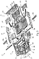
- Fig. 3 shows an exploded view of a universal body obtained as according to the present invention;
- Fig. 4 shows a top plan view of the body in Fig. 3;
- Fig. 5 shows a section taken along line V-V of the body of Fig. 4;
- Fig. 6 shows a partial front elevation of the body in Fig. 4;
- Fig. 7 shows a partial rear elevation of the body in Fig. 4.
- With reference to Fig.s 1 to 5, number 1 indicates a vehicle, in particular, a current production vehicle provided with an electric traction system, in which a series of
batteries 2 is housed to feed anelectric engine 3. By "current production vehicle" it is herein indicated that electric traction vehicle 1 is identical, on the outside, to the traditional propulsion (endothermic engine) type of same. - Vehicle 1 being provided with a
body 4 comprising, in turn, a flatbed-like base structure 5 and a plurality oftelescoping members 6, that may be fixed to base structure 5 to obtain a unitized body-work. - According to the present invention, base structure 5 of vehicle 1 is identical, both in the electric traction type, shown in the accompanying drawings, and in the "current production" type, which is not being shown hereby for simplicitys sake, provided, in the known fashion, with an endothermic propulsor. Base structure 5 comprises a box-like rectangular frame front substructure 7 presenting two

backstays 8 extending to the front, cantilevered and connected to each other, in connection with their relevantfree ends 11, bycross member 12. - Base structure 5 further comprises a first flatbed-
like substructure 13, connected, so as to form an angle, with a relevant box-like cross member 14 and defining, along with the latter, a rear portion orsubstructure 15 ofbody 4; base structure 5 finally comprises a second flatbed-like substructure 16, connecting box-like front substructure 7 and said first flatbed-likerear substructure 13;second substructure 16 defining alower part 18 of apassenger compartment 21 of vehicle 1. - According to the present invention, the shape of base structure 5 is such, that it is capable of receiving, integrally fixed to
substructures number 22, capable of defining, together with said substructures, box-liketridimensional body portions 23, so as to stiffen base structure 5. - Front substructure 7 comprises a base element 24 essentially made up of two
body center pillars 25, tworelevant cross members 26, connected with each other bycenter pillars 25, tworelevant panel members 35 and of a box-like member 34a, in the shape of an overturned U, inserted between panels 35 (only one of which is visible in Fig. 3); one of said reinforcingmembers 22 being defined by a box-like frame member 27, comprising twobackstays 28,cross member 29 connectingbackstays 28 to two relevantreticular center pillars 31, basically triangular in shape; twobackstays 28 are linked to a relevantlower cross member 26a ofcross members 26 of base member 24, whereastriangular center pillars 31 are connected tofront cross member 12 of front substructure 7. A further reinforcingmember 22 being defined bymember 36, tunnel-like, overlappingmember 34a and linked toupper cross member 26 and, through relevant opposite bar-shaped additional cross members, marked bynumber 38, to center pillars 25 (Fig. 4), defining, in such a way, one of box-like units 23. - Second flatbed-
like substructure 16 comprises two box-like side backstays 33 defining two relevant underdoor outer members and comprising acenter member 34, essentially tunnel-like, and twopanel members 35a (similar to members 35) linking tunnel-like member 34 tobackstays 33; tunnel-like member 34 is connected, up front, with relevant tunnel-like member 36 of substructure 7 and presents, to the rear,portion 37 linked to flatbed-like substructure 13. Finally,substructure 16 also comprises two relevant backstays 41, located to the side of and under tunnel-like member 34 and whose cross-section is in the shape of an overturned U, which are connected, along their whole length, withmember 34, along one edge, and with overhangingpanel 35a, along the other edge, thus creating, withmember 34 andpanels 35a, a further box-like reinforcing structure 23, arranged lengthwise along the vehicle center line; such a structure being integrated with the front reinforcing structure represented byframe 27, in that backstays 41 are connected, for instance by welding, withrelevant backstays 28 of front substructure 7, in connection withcenter pillars 25 of base member 24. - Moreover, according to the present invention, box-
like center member 34 is linked, in connection with the joint withmember 36, to tworelevant cross members 38a, in the shape of an overturned U, arranged along the connection betweenpanels member 34; thus, two further box-like reinforcingmembers 23 are obtained (Fig. 4), transversally arranged with respect to the vehicle, connected with the center member and linking the two portions oflower part 18 of the vehicle passengers compartment, defined bypanels - In relation to the connection between
substructures dihedral members 42 inserted between relevantrear portions 43, folded upwards, ofpanel members 35a and flatbed-like substructure 13, to create further box-likestiffening structures 23, arranged transversally. Flatbed-like substructure 13 consists ofmember 44, essentially in the shape of a horse-shoe, into which apanel member 45 is inserted, whereon relevantstiffening ribs 46 are obtained. - The non-limiting example, described hereinabove, clearly shows the configuration of both base 5 and
additional body members 22 to be such, as to create, together, besides tridimensional stiffening and reinforcing members of body 1 in its whole, without causing, though, either base shape and structure to be altered, also housing members forbatteries 2 feeding engine/engines 3. In the case in point,batteries 2 are housed inside the tunnel-like structure created bymembers members backstays 28,cross member 29 andreticular center pillars 31. Moreover, such housing and stiffening structures are arranged one after the other, without interruption and outside the bulk ofactual passenger compartment 21. In this way, were vehicle 1 to undergo a violent impact, consequently coming to a halt,batteries 2 are allowed inertial motion, thus being thrust out of vehicle 1 up front, without penetratingpassenger compartment 21, and, therefore, without jeopardizing passengerslife. Besides,most batteries 2 and, therefore, their weight, are transferred to the front ofpassenger compartment 21, in connection with front substructure 7, which may be easily reinforced without causing the overall body structure to be altered, and are already located outsidepassengers compartment 21. - In conclusion, the universal body, as described hereinabove, is that of a regular current production vehicle provided with an endothermic engine, but for the presence of a few additional reinforcement members suitably applied; so that a low-budget universal body is obtained, which, no ridesigning of the body being necessary, perfectly fits such a vehicle, too, as may be provided with an electric traction system, allowing for the higher static stress, caused by the weight of the batteries feeding the electric engine/engines, to be born, and for the higher dynamic stress, caused by possible impacts of the vehicle against possible obstacles/other vehicles, to be absorbed, said stress being stress amplified, in comparison to the corresponding current production vehicles provided with endothermic engine, due to the bigger mass of the electric vehicle, owing to the presence of said batteries.
Claims (6)
- A universal body (4) for a vehicle (1), such as may be both of the traditional propulsion type and of the electric traction type, identical on the outside, comprising a base structure (5), identical for both types and comprising, in turn, a front frame substructure (7), a rear substructure (15) and a flatbed-like structure (16) defining a lower part (18) of a passengers compartment (21) of vehicle (1) and connecting front substructure (7) and rear substructure (15) with each other; characterized by the fact that the shape of base structure (5) is such, as to be capable of receiving, integrally fixed to said substructures (7,15,16), as to the embodiment relating to the electric traction type, a plurality of reinforcement members (22), capable of defining, along with substructures (7,15,16), tridimensional stiffening portions (23) of the body of base structure (5); said stiffening portions (23) being capable of containing the batteries and being arranged in such a way, as to transfer the greatest part of the batteries weight on to front substructure (7).
- A body as claimed in Claim 1, characterized by the fact that said base structure (5) is generally flatbed-like, said body further comprising a plurality of telescoping members (6) capable of being fixed to base structure (5) to create a unitized body-work; base structure (5) comprising: a front box-like rectangular frame substructure (7), comprising, in turn, two backstays (8) extending to the front, cantilevered and linked to each other, in connection with relevant free ends (11), by means of a cross member (12); a first flatbed-like substructure (13) connected, so as to form an angle, with a relevant box-like cross member (14) and defining, together with the latter, a rear substructure (15) of said body (4); and a further flatbed-like substructure (16) connecting box-like front substructure (7) with first rear flatbed-like substructure (13).
- A universal body (4) as claimed in Claim 2, characterized by the fact that front substructure (7) comprises a base member (24) comprising two center pillars (25) and two relevant cross members (26) connecting said center pillars; a first reinforcement member (22) being defined by a box-like frame member (27) comprising two backstays (28), a cross member (29) connecting said backstays (28) and two relevant reticular center pillars (31), essentially triangular in shape; said two backstays (28) being connected with a relevant lower cross member (26a) of cross members (26) of base member (24); and said two triangular center pillars (31) being connected with front cross member (12) of said front substructure (7).
- A universal body (4) as claimed in Claim 3, characterized by the fact that second flatbed-like substructure (16) comprises two box-like side backstays (33) defining two relevant underdoor outer members (33), a center member (34), essentially in the shape of a tunnel, and two panel members (35a) connecting tunnel-like member (34) with said side backstays (33); tunnel-like member (34) being connected, towards its front, with a relevant tunnel-like member (36), fixed in an integral fashion, linked to base member (24) of front substructure (7) and, towards its rear, presenting a portion (37) connected with panel members (35a) and with said first flatbed-like substructure (13); tunnel-like member (36), connected with said base member (24), being linked, to the side, by means of two relevant opposite cross members (38), to said center pillars (25) of base member (24) of front substructure (7) and tunnel-like member (34) of second flatbed-like substructure (16) being linked, in respect to the connection with the other tunnel-like member (36), to two relevant cross members (38a), in the shape of an overturned U, arranged along the connection between said panels (35a) of second flatbed-like substructure (16) and relevant panels (35) being part of front substructure (7) and transversally connected with said box-like side backstays (33).
- A universal body (4) as claimed in Claim 4, characterized by the fact that said tunnel-like member (34) of second flatbed-like substructure (16) is provided, in an integral fashion, below and at the side, with two relevant backstays (41), connected with said backstays (8) of front substructure (7) in connection with said center pillars (25) of said base member (24); between said second and said first flatbed-like substructure (13,16) there being further inserted two relevant dihedral members (42), inserted between said first flatbed-like substructure (13) and relevant rear portions (43) of said two panels (35a) of second flatbed-like substructure (16), folded upwards.
- A universal body (4) as claimed in Claim 5, characterized by the fact that said first flatbed-like substructure (13) consists of a first member (44), essentially in the shape of a horse-shoe, wherein panel member (45) is inserted, relevant reinforcement ribs (46) being obtained on the latter.
Applications Claiming Priority (2)
| Application Number | Priority Date | Filing Date | Title |
|---|---|---|---|
| ITTO920096A IT1256854B (en) | 1992-02-07 | 1992-02-07 | MULTI-PURPOSE BODY FOR A VEHICLE. |
| ITTO920096 | 1992-02-07 |
Publications (2)
| Publication Number | Publication Date |
|---|---|
| EP0554889A1 true EP0554889A1 (en) | 1993-08-11 |
| EP0554889B1 EP0554889B1 (en) | 1996-09-11 |
Family
ID=11410016
Family Applications (1)
| Application Number | Title | Priority Date | Filing Date |
|---|---|---|---|
| EP93101821A Expired - Lifetime EP0554889B1 (en) | 1992-02-07 | 1993-02-05 | Universal body for a vehicle |
Country Status (4)
| Country | Link |
|---|---|
| EP (1) | EP0554889B1 (en) |
| DE (1) | DE69304559T2 (en) |
| IT (1) | IT1256854B (en) |
| PL (1) | PL170801B1 (en) |
Cited By (7)
| Publication number | Priority date | Publication date | Assignee | Title |
|---|---|---|---|---|
| EP0618128A1 (en) * | 1993-02-27 | 1994-10-05 | Esoro Ag | Lightweight road vehicle with load-bearing structure |
| US5704644A (en) * | 1993-02-27 | 1998-01-06 | Esoro Ag | Lightweight road vehicle with strengthening structure |
| CN100364805C (en) * | 2003-04-03 | 2008-01-30 | 杭州莱切克斯小型电动车有限公司 | electric car |
| WO2011055936A3 (en) * | 2009-11-03 | 2011-10-27 | (주)브이이엔에스 | Motor vehicle |
| US20130026786A1 (en) * | 2011-07-26 | 2013-01-31 | Toyota Jidosha Kabushiki Kaisha | Battery protection structure for automobile |
| JP2013532606A (en) * | 2010-07-23 | 2013-08-19 | ルノー エス.ア.エス. | Chassis with raised rear floor and method of assembly |
| EP3293944A1 (en) * | 2016-09-07 | 2018-03-14 | Thunder Power New Energy Vehicle Development Company Limited | Vehicle tunnel floor structure |
Families Citing this family (3)
| Publication number | Priority date | Publication date | Assignee | Title |
|---|---|---|---|---|
| DE10154353B4 (en) * | 2000-11-06 | 2012-10-18 | General Motors Corp. | Modular vehicle construction |
| DE102011115763A1 (en) * | 2011-10-12 | 2013-04-18 | Volkswagen Aktiengesellschaft | Body structure for an electrically driven passenger vehicle |
| DE102017200999A1 (en) | 2017-01-23 | 2018-07-26 | Robert Bosch Gmbh | Structural system for a vehicle, in particular a motor vehicle |
Citations (12)
| Publication number | Priority date | Publication date | Assignee | Title |
|---|---|---|---|---|
| US1414292A (en) * | 1918-12-28 | 1922-04-25 | Lubeck Hilding | Electric motor car |
| FR867778A (en) * | 1940-11-23 | 1941-11-27 | Chassis for electric vehicles or others | |
| FR1262367A (en) * | 1959-08-28 | 1961-05-26 | Daimler Benz Ag | Installation of the chassis floor for vehicles, in particular for motor cars |
| US3493068A (en) * | 1968-07-05 | 1970-02-03 | Penrose Lucas Albright | Electric battery in combination with vehicle frame |
| FR2249544A5 (en) * | 1973-10-30 | 1975-05-23 | Gadriot Roland | Vehicle with battery electric propulsion - has plastics chassis members which also act as battery containers reducing weight |
| US3983952A (en) * | 1970-11-16 | 1976-10-05 | Mckee Robert S | Electric vehicle having backbone containing tray of power cells |
| FR2318757A1 (en) * | 1975-07-25 | 1977-02-18 | Lucas Industries Ltd | DEVICE FOR ELECTRICAL CONTROL OF A VEHICLE |
| US4216839A (en) * | 1978-07-20 | 1980-08-12 | Unique Mobility Inc. | Electrically powered motor vehicle |
| DE3141164A1 (en) * | 1981-10-16 | 1983-04-28 | Volkswagenwerk Ag, 3180 Wolfsburg | Electrically driven vehicle |
| EP0390752A1 (en) * | 1989-03-30 | 1990-10-03 | FIAT AUTO S.p.A. | A rear subassembly for a motor vehicle floor |
| EP0397544A1 (en) * | 1989-05-10 | 1990-11-14 | Automobiles Peugeot | Front structure for an automotive vehicle and vehicle provided with this structure |
| US5002333A (en) * | 1987-08-11 | 1991-03-26 | Honda Giken Kogyo Kabushiki Kaisha | Under frame of a motor vehicle |
-
1992
- 1992-02-07 IT ITTO920096A patent/IT1256854B/en active IP Right Grant
-
1993
- 1993-02-05 DE DE69304559T patent/DE69304559T2/en not_active Expired - Fee Related
- 1993-02-05 EP EP93101821A patent/EP0554889B1/en not_active Expired - Lifetime
- 1993-02-05 PL PL93297664A patent/PL170801B1/en not_active IP Right Cessation
Patent Citations (12)
| Publication number | Priority date | Publication date | Assignee | Title |
|---|---|---|---|---|
| US1414292A (en) * | 1918-12-28 | 1922-04-25 | Lubeck Hilding | Electric motor car |
| FR867778A (en) * | 1940-11-23 | 1941-11-27 | Chassis for electric vehicles or others | |
| FR1262367A (en) * | 1959-08-28 | 1961-05-26 | Daimler Benz Ag | Installation of the chassis floor for vehicles, in particular for motor cars |
| US3493068A (en) * | 1968-07-05 | 1970-02-03 | Penrose Lucas Albright | Electric battery in combination with vehicle frame |
| US3983952A (en) * | 1970-11-16 | 1976-10-05 | Mckee Robert S | Electric vehicle having backbone containing tray of power cells |
| FR2249544A5 (en) * | 1973-10-30 | 1975-05-23 | Gadriot Roland | Vehicle with battery electric propulsion - has plastics chassis members which also act as battery containers reducing weight |
| FR2318757A1 (en) * | 1975-07-25 | 1977-02-18 | Lucas Industries Ltd | DEVICE FOR ELECTRICAL CONTROL OF A VEHICLE |
| US4216839A (en) * | 1978-07-20 | 1980-08-12 | Unique Mobility Inc. | Electrically powered motor vehicle |
| DE3141164A1 (en) * | 1981-10-16 | 1983-04-28 | Volkswagenwerk Ag, 3180 Wolfsburg | Electrically driven vehicle |
| US5002333A (en) * | 1987-08-11 | 1991-03-26 | Honda Giken Kogyo Kabushiki Kaisha | Under frame of a motor vehicle |
| EP0390752A1 (en) * | 1989-03-30 | 1990-10-03 | FIAT AUTO S.p.A. | A rear subassembly for a motor vehicle floor |
| EP0397544A1 (en) * | 1989-05-10 | 1990-11-14 | Automobiles Peugeot | Front structure for an automotive vehicle and vehicle provided with this structure |
Non-Patent Citations (3)
| Title |
|---|
| PATENT ABSTRACTS OF JAPAN vol. 15, no. 457 (M-1181)20 November 1991 & JP-A-03 193 568 ( MAZDA ) 23 August 1991 * |
| PATENT ABSTRACTS OF JAPAN vol. 3, no. 76 (M-64)29 June 1979 & JP-A-54 053 417 ( HONDA ) 26 April 1979 * |
| PATENT ABSTRACTS OF JAPAN vol. 7, no. 237 (M-250)(1382) 21 October 1983 & JP-A-58 126 263 ( NISSAN ) 27 July 1983 * |
Cited By (9)
| Publication number | Priority date | Publication date | Assignee | Title |
|---|---|---|---|---|
| EP0618128A1 (en) * | 1993-02-27 | 1994-10-05 | Esoro Ag | Lightweight road vehicle with load-bearing structure |
| US5704644A (en) * | 1993-02-27 | 1998-01-06 | Esoro Ag | Lightweight road vehicle with strengthening structure |
| CN100364805C (en) * | 2003-04-03 | 2008-01-30 | 杭州莱切克斯小型电动车有限公司 | electric car |
| WO2011055936A3 (en) * | 2009-11-03 | 2011-10-27 | (주)브이이엔에스 | Motor vehicle |
| JP2013532606A (en) * | 2010-07-23 | 2013-08-19 | ルノー エス.ア.エス. | Chassis with raised rear floor and method of assembly |
| US20130026786A1 (en) * | 2011-07-26 | 2013-01-31 | Toyota Jidosha Kabushiki Kaisha | Battery protection structure for automobile |
| US8708402B2 (en) * | 2011-07-26 | 2014-04-29 | Toyota Jidosha Kabushiki Kaisha | Battery protection structure for automobile |
| EP3293944A1 (en) * | 2016-09-07 | 2018-03-14 | Thunder Power New Energy Vehicle Development Company Limited | Vehicle tunnel floor structure |
| US9981698B2 (en) | 2016-09-07 | 2018-05-29 | Thunder Power New Energy Vehicle Development Company Limited | Vehicle tunnel floor structure |
Also Published As
| Publication number | Publication date |
|---|---|
| ITTO920096A1 (en) | 1993-08-07 |
| DE69304559D1 (en) | 1996-10-17 |
| ITTO920096A0 (en) | 1992-02-07 |
| IT1256854B (en) | 1995-12-27 |
| DE69304559T2 (en) | 1997-02-13 |
| PL170801B1 (en) | 1997-01-31 |
| EP0554889B1 (en) | 1996-09-11 |
| PL297664A1 (en) | 1993-09-06 |
Similar Documents
| Publication | Publication Date | Title |
|---|---|---|
| EP0554889B1 (en) | Universal body for a vehicle | |
| US5988734A (en) | Passenger vehicle structure | |
| US6196621B1 (en) | Apparatus for transferring impact energy from a tire and wheel assembly of a motor vehicle to a sill | |
| US2856226A (en) | Vehicle frame assembly | |
| US4998761A (en) | Reinforced impact bar for a bumper assembly | |
| US2389907A (en) | Vehicle structure | |
| JP3079131B2 (en) | Vehicle drive engine layout | |
| US20140110925A1 (en) | Front subframe for a narrow offset collision | |
| EP1655223A3 (en) | Satellite dispenser | |
| JPH07108956A (en) | Electric vehicle battery frame mounting structure | |
| KR880010952A (en) | Safety steering wheel | |
| JPS62101566A (en) | Energy absorber | |
| KR960000697A (en) | Car body structure | |
| EP0856455A3 (en) | Body structure for vehicle | |
| CA2136134A1 (en) | Light Weight Steel Auto Body Construction | |
| SE445197B (en) | FORDONSDORR | |
| ES2252860T3 (en) | FREE EJECTION SEAT AND SAFETY GUARD FOR INDO-SKELETTIC SHOCK. | |
| US4303033A (en) | Portable pontoon boat | |
| CN216185522U (en) | Vehicle-mounted middle battery pack mounting framework | |
| JPS6416478A (en) | Module structure of car and application to automatic assembly of car | |
| ES2277603T3 (en) | BODY STRUCTURE ASSEMBLY THAT INCLUDES SUSPENSION HOOD REINFORCEMENTS. | |
| US4552401A (en) | Folding roof for vehicles, especially passenger motor vehicles | |
| JPS6463479A (en) | Frame structure of automobile | |
| CN113734297A (en) | Middle and rear floor board structure | |
| SE507430C2 (en) | highchair Events |
Legal Events
| Date | Code | Title | Description |
|---|---|---|---|
| PUAI | Public reference made under article 153(3) epc to a published international application that has entered the european phase |
Free format text: ORIGINAL CODE: 0009012 |
|
| AK | Designated contracting states |
Kind code of ref document: A1 Designated state(s): DE ES FR GB IT SE |
|
| 17P | Request for examination filed |
Effective date: 19940128 |
|
| 17Q | First examination report despatched |
Effective date: 19950327 |
|
| GRAG | Despatch of communication of intention to grant |
Free format text: ORIGINAL CODE: EPIDOS AGRA |
|
| GRAH | Despatch of communication of intention to grant a patent |
Free format text: ORIGINAL CODE: EPIDOS IGRA |
|
| GRAH | Despatch of communication of intention to grant a patent |
Free format text: ORIGINAL CODE: EPIDOS IGRA |
|
| GRAA | (expected) grant |
Free format text: ORIGINAL CODE: 0009210 |
|
| AK | Designated contracting states |
Kind code of ref document: B1 Designated state(s): DE ES FR GB IT SE |
|
| PG25 | Lapsed in a contracting state [announced via postgrant information from national office to epo] |
Ref country code: ES Free format text: THE PATENT HAS BEEN ANNULLED BY A DECISION OF A NATIONAL AUTHORITY Effective date: 19960911 |
|
| REF | Corresponds to: |
Ref document number: 69304559 Country of ref document: DE Date of ref document: 19961017 |
|
| ITF | It: translation for a ep patent filed | ||
| PG25 | Lapsed in a contracting state [announced via postgrant information from national office to epo] |
Ref country code: SE Effective date: 19961211 |
|
| ET | Fr: translation filed | ||
| PLBE | No opposition filed within time limit |
Free format text: ORIGINAL CODE: 0009261 |
|
| STAA | Information on the status of an ep patent application or granted ep patent |
Free format text: STATUS: NO OPPOSITION FILED WITHIN TIME LIMIT |
|
| 26N | No opposition filed | ||
| REG | Reference to a national code |
Ref country code: GB Ref legal event code: IF02 |
|
| PGFP | Annual fee paid to national office [announced via postgrant information from national office to epo] |
Ref country code: GB Payment date: 20070205 Year of fee payment: 15 |
|
| PGFP | Annual fee paid to national office [announced via postgrant information from national office to epo] |
Ref country code: DE Payment date: 20070425 Year of fee payment: 15 |
|
| PGFP | Annual fee paid to national office [announced via postgrant information from national office to epo] |
Ref country code: IT Payment date: 20070517 Year of fee payment: 15 |
|
| PGFP | Annual fee paid to national office [announced via postgrant information from national office to epo] |
Ref country code: FR Payment date: 20070130 Year of fee payment: 15 |
|
| GBPC | Gb: european patent ceased through non-payment of renewal fee |
Effective date: 20080205 |
|
| REG | Reference to a national code |
Ref country code: FR Ref legal event code: ST Effective date: 20081031 |
|
| PG25 | Lapsed in a contracting state [announced via postgrant information from national office to epo] |
Ref country code: DE Free format text: LAPSE BECAUSE OF NON-PAYMENT OF DUE FEES Effective date: 20080902 |
|
| PG25 | Lapsed in a contracting state [announced via postgrant information from national office to epo] |
Ref country code: FR Free format text: LAPSE BECAUSE OF NON-PAYMENT OF DUE FEES Effective date: 20080229 |
|
| PG25 | Lapsed in a contracting state [announced via postgrant information from national office to epo] |
Ref country code: GB Free format text: LAPSE BECAUSE OF NON-PAYMENT OF DUE FEES Effective date: 20080205 |
|
| PG25 | Lapsed in a contracting state [announced via postgrant information from national office to epo] |
Ref country code: IT Free format text: LAPSE BECAUSE OF NON-PAYMENT OF DUE FEES Effective date: 20080205 |