EP0554609B1 - Screw stopping mechanism for spectacles - Google Patents
Screw stopping mechanism for spectacles Download PDFInfo
- Publication number
- EP0554609B1 EP0554609B1 EP19920308756 EP92308756A EP0554609B1 EP 0554609 B1 EP0554609 B1 EP 0554609B1 EP 19920308756 EP19920308756 EP 19920308756 EP 92308756 A EP92308756 A EP 92308756A EP 0554609 B1 EP0554609 B1 EP 0554609B1
- Authority
- EP
- European Patent Office
- Prior art keywords
- screw
- spectacles
- stopping mechanism
- aperture
- pair
- Prior art date
- Legal status (The legal status is an assumption and is not a legal conclusion. Google has not performed a legal analysis and makes no representation as to the accuracy of the status listed.)
- Expired - Lifetime
Links
- 230000007246 mechanism Effects 0.000 title claims description 21
- 230000003247 decreasing effect Effects 0.000 claims description 6
- 238000005476 soldering Methods 0.000 description 2
- 230000007423 decrease Effects 0.000 description 1
- 238000000034 method Methods 0.000 description 1
- 238000000465 moulding Methods 0.000 description 1
- 238000010079 rubber tapping Methods 0.000 description 1
Images


Classifications
-
- G—PHYSICS
- G02—OPTICS
- G02C—SPECTACLES; SUNGLASSES OR GOGGLES INSOFAR AS THEY HAVE THE SAME FEATURES AS SPECTACLES; CONTACT LENSES
- G02C5/00—Constructions of non-optical parts
- G02C5/22—Hinges
- G02C5/2281—Special hinge screws
-
- G—PHYSICS
- G02—OPTICS
- G02C—SPECTACLES; SUNGLASSES OR GOGGLES INSOFAR AS THEY HAVE THE SAME FEATURES AS SPECTACLES; CONTACT LENSES
- G02C1/00—Assemblies of lenses with bridges or browbars
- G02C1/06—Bridge or browbar secured to or integral with closed rigid rims for the lenses
- G02C1/08—Bridge or browbar secured to or integral with closed rigid rims for the lenses the rims being tranversely split and provided with securing means
-
- G—PHYSICS
- G02—OPTICS
- G02C—SPECTACLES; SUNGLASSES OR GOGGLES INSOFAR AS THEY HAVE THE SAME FEATURES AS SPECTACLES; CONTACT LENSES
- G02C2200/00—Generic mechanical aspects applicable to one or more of the groups G02C1/00 - G02C5/00 and G02C9/00 - G02C13/00 and their subgroups
- G02C2200/20—Friction elements
Definitions
- This invention relates to a screw stopping mechanism for use in a pair of spectacles.
- two parts of the pair of spectacles are interconnected using a male threaded screw which engages with a female thread in a bore formed in one part of the pair of spectacles, the screw extending through a clearance bore provided in the other part of the pair of spectacles.
- a screw stopping mechanism for use in connecting first and second parts of a pair of spectacles comprising a cone projection axially split as to form a plurality of arc segments and being provided on a first part of said pair of spectacles, an internally screw threaded aperture extending through said first part and said split cone projection, the screw threaded aperture being of decreasing diameter, and a screw arranged to be inserted into said aperture in the direction of decreasing diameter, said screw having a diameter greater than the minimum diameter of the aperture.
- the screw stopping mechanism shown in Figures 1 to 5 comprises a first part 1 forming part of, or arranged to be attached to, the frame of pair of spectacles, and a second part 2 forming part of, or arranged to be attached to, an arm of the pair of spectacles, the first and second parts 1, 2 forming a hinged connection between the frame and the arm.
- first and second parts 1, 2 are arranged to be attached to their respective parts of the pair of spectacles, it will be understood that the first and second parts 1, 2 may be attached by soldering or using any other suitable technique.
- the first part 1 includes a pair of parallel flanges, spaced apart from each other, each flange being provided with an aperture, the apertures being coaxial with each other.
- the second part 2 includes an extension arranged to fit in the gap defined by the flanges of the first part 1. The extension is also provided with an aperture which is arranged to be coaxial with the apertures of the flanges when the extension is inserted into the gap.
- a split cone projection is provided on a face of a first flange of the first part facing away from the other flange, the aperture 12 extending through said projection.
- the projection includes four splits, and hence, has the appearance of four arcs 11 surrounding the aperture 12.
- the inner surface of the aperture 12 is provided with a female screw thread, the thread extending onto the inner surface of the projection.
- the diameter of the aperture 12 decreases in the direction away from the other flange so that the portion of the aperture of minimum diameter is at the tip of the projection.
- Such a screw thread may be provided by commencing tapping from the side of the first flange closest to the other flange. It will be understood that when the tap reaches the projection, the four arcs 11 defining the projection will expand outwardly, so that on removal of the tap, and the return of the arcs 11 of the projection to their original positions, the internal thread will be of decreasing diameter.
- the apertures formed in the other flange and in the extension to the second part 2 are of substantially equal diameter, and are larger in diameter than the threaded aperture 12 formed in the first flange. These apertures act as clearance bores, and so must be of slightly greater diameter than a screw 3 extending through them, in use.
- the extension of the second part 2 is inserted into the gap defined by the flanges of the first part 1 such that the apertures align, and a threaded screw 3 of constant diameter is inserted into the aligned apertures from said other flange.
- the screw 3 is then rotated, the thread provided on the screw 3 engaging with the female thread provided on the inner surface of the aperture 12.
- the screw 3 is rotated until the tip of the screw 3 reaches the split cone projection whereupon further rotation of the screw 3 results in the arcs of the projection being forced outwardly so as to increase the inner diameter of the aperture 12.
- Figures 6 to 10 show a similar screw stopping mechanism to that shown in Figures 1 to 5 and described above, but in this case, the first part 4 of the screw stopping mechanism is attached to an upper part of the frame of the pair of spectacles, and the second part 5 is attached to the lower part of the frame.
- the first part 4 comprises a single flange provided with an aperture 41 as described above in relation to the aperture 12 provided in the first flange.
- the second part 5 also comprises a single flange provided with an aperture arranged to align with the aperture 41 of the first part 4.
- a split cone projection of the type described above is provided on the first part 4, the aperture 41 provided in the first part 4 extending through the projection.
- the apertures 41 provided in the first and second parts 4, 5 are aligned, a screw 6 inserted into the aligned apertures, and the screw 6 tightened until the split cone projection causes the screw 6 to be tightly gripped.
- first and second parts 4, 5 of the screw stopping mechanism may be attached to the frame by soldering or other means, or they could form part of an integral molding.
- the split cone projection forming part of the first part of the pair of spectacles can be shaped so as to constitute part of the ornamental design of the pair of spectacles.
Landscapes
- Physics & Mathematics (AREA)
- Health & Medical Sciences (AREA)
- General Physics & Mathematics (AREA)
- Ophthalmology & Optometry (AREA)
- Optics & Photonics (AREA)
- Eyeglasses (AREA)
Description
- This invention relates to a screw stopping mechanism for use in a pair of spectacles.
- In most conventional pairs of spectacles, two parts of the pair of spectacles are interconnected using a male threaded screw which engages with a female thread in a bore formed in one part of the pair of spectacles, the screw extending through a clearance bore provided in the other part of the pair of spectacles.
- The screws used in such applications are generally very small in size, and the frictional force between the screw and the threaded bore of the pair of spectacles is often not enough to prevent rotation of the screw due to the pair of spectacles being vibrated slightly. It is therefore common for such screws to become loose.
- It is an object of the invention to provide a screw stopping mechanism in which the loosening of the screw due to slight vibration of the pair of spectacles is reduced.
- In accordance with the present invention there is provided a screw stopping mechanism for use in connecting first and second parts of a pair of spectacles comprising a cone projection axially split as to form a plurality of arc segments and being provided on a first part of said pair of spectacles, an internally screw threaded aperture extending through said first part and said split cone projection, the screw threaded aperture being of decreasing diameter, and a screw arranged to be inserted into said aperture in the direction of decreasing diameter, said screw having a diameter greater than the minimum diameter of the aperture.
- The invention will further be described, by way of example, with reference to the accompanying drawings, in which:
- Figure 1 is an exploded view of a screw stopping mechanism of a first embodiment;
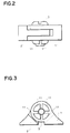
- Figure 2 is a plan view of the screw stopping mechanism of Figure 1;
- Figure 3 is a front view of the screw stopping mechanism of Figure 1;
- Figure 4 is a partly enlarged sectional view of a hinge piece using the screw stopping mechanism of Figure 1;
- Figure 5 is a partly enlarged sectional view of the hinge piece of Figure 4;
- Figure 6 is an exploded view of a screw stopping mechanism of a second embodiment;
- Figure 7 is a front view of the screw stopping mechanism of Figure 6;
- Figure 8 is a plan view of the screw stopping mechanism of Figure 6;
- Figure 9 is a sectional view of part of the screw stopping mechanism of Figure 6;
- Figure 10 is a sectional view of the screw stopping mechanism of Figure 6; and
- Figure 11 is a perspective view of a pair of spectacles incorporating the screw stopping mechanisms of the first and second embodiments.
- The screw stopping mechanism shown in Figures 1 to 5 comprises a
first part 1 forming part of, or arranged to be attached to, the frame of pair of spectacles, and asecond part 2 forming part of, or arranged to be attached to, an arm of the pair of spectacles, the first andsecond parts second parts second parts first part 1 includes a pair of parallel flanges, spaced apart from each other, each flange being provided with an aperture, the apertures being coaxial with each other. Thesecond part 2 includes an extension arranged to fit in the gap defined by the flanges of thefirst part 1. The extension is also provided with an aperture which is arranged to be coaxial with the apertures of the flanges when the extension is inserted into the gap. - A split cone projection is provided on a face of a first flange of the first part facing away from the other flange, the
aperture 12 extending through said projection. The projection includes four splits, and hence, has the appearance of fourarcs 11 surrounding theaperture 12. The inner surface of theaperture 12 is provided with a female screw thread, the thread extending onto the inner surface of the projection. As clearly shown in Figure 4, the diameter of theaperture 12 decreases in the direction away from the other flange so that the portion of the aperture of minimum diameter is at the tip of the projection. Such a screw thread may be provided by commencing tapping from the side of the first flange closest to the other flange. It will be understood that when the tap reaches the projection, the fourarcs 11 defining the projection will expand outwardly, so that on removal of the tap, and the return of thearcs 11 of the projection to their original positions, the internal thread will be of decreasing diameter. - The apertures formed in the other flange and in the extension to the
second part 2 are of substantially equal diameter, and are larger in diameter than the threadedaperture 12 formed in the first flange. These apertures act as clearance bores, and so must be of slightly greater diameter than ascrew 3 extending through them, in use. - In use, the extension of the
second part 2 is inserted into the gap defined by the flanges of thefirst part 1 such that the apertures align, and a threadedscrew 3 of constant diameter is inserted into the aligned apertures from said other flange. Thescrew 3 is then rotated, the thread provided on thescrew 3 engaging with the female thread provided on the inner surface of theaperture 12. Thescrew 3 is rotated until the tip of thescrew 3 reaches the split cone projection whereupon further rotation of thescrew 3 results in the arcs of the projection being forced outwardly so as to increase the inner diameter of theaperture 12. It will be understood that the provision of theaperture 12 of decreasing diameter results in the application of pressure on thescrew 3, and hence reduces the likelihood of thescrew 3 becoming loosened during slight vibration of the pair of spectacles. - Figures 6 to 10 show a similar screw stopping mechanism to that shown in Figures 1 to 5 and described above, but in this case, the
first part 4 of the screw stopping mechanism is attached to an upper part of the frame of the pair of spectacles, and thesecond part 5 is attached to the lower part of the frame. Thefirst part 4 comprises a single flange provided with anaperture 41 as described above in relation to theaperture 12 provided in the first flange. Thesecond part 5 also comprises a single flange provided with an aperture arranged to align with theaperture 41 of thefirst part 4. - A split cone projection of the type described above is provided on the
first part 4, theaperture 41 provided in thefirst part 4 extending through the projection. In use, theapertures 41 provided in the first andsecond parts screw 6 inserted into the aligned apertures, and thescrew 6 tightened until the split cone projection causes thescrew 6 to be tightly gripped. - It will be understood that the first and
second parts - As shown in Figure 11, the split cone projection forming part of the first part of the pair of spectacles can be shaped so as to constitute part of the ornamental design of the pair of spectacles.
Claims (3)
- A screw stopping mechanism for use in connecting first and second parts of a pair of spectacles comprising a cone projection axially split as to form a plurality of arc segments and being provided on the first part (1) of said pair of spectacles, an internally screw threaded aperture (12) extending through said first part (1) and said split cone projection, the screw threaded aperture (12) being of decreasing diameter, and a screw (3) arranged to be inserted into said aperture (12) in the direction of decreasing diameter, said screw (3) having a diameter greater than the minimum diameter of the aperture (12).
- A screw stopping mechanism as claimed in Claim 1, characterized in that said split cone projection includes four arc segments.
- A screw stopping mechanism as claimed in Claim 1 or Claim 2, characterized in that the second part (2) of said pair of spectacles includes a clearance bore through which said screw (3) extends in use.
Applications Claiming Priority (2)
| Application Number | Priority Date | Filing Date | Title |
|---|---|---|---|
| JP5437592A JPH05215993A (en) | 1992-02-04 | 1992-02-04 | Clamp type screw loosening mechanism for spectacles |
| JP54375/92 | 1992-02-04 |
Publications (2)
| Publication Number | Publication Date |
|---|---|
| EP0554609A1 EP0554609A1 (en) | 1993-08-11 |
| EP0554609B1 true EP0554609B1 (en) | 1996-08-28 |
Family
ID=12968932
Family Applications (1)
| Application Number | Title | Priority Date | Filing Date |
|---|---|---|---|
| EP19920308756 Expired - Lifetime EP0554609B1 (en) | 1992-02-04 | 1992-09-25 | Screw stopping mechanism for spectacles |
Country Status (3)
| Country | Link |
|---|---|
| EP (1) | EP0554609B1 (en) |
| JP (1) | JPH05215993A (en) |
| DE (1) | DE69213206T2 (en) |
Families Citing this family (3)
| Publication number | Priority date | Publication date | Assignee | Title |
|---|---|---|---|---|
| DE19602923C1 (en) * | 1996-01-22 | 1997-04-03 | Huma Gmbh Feinwerktechn Produk | Spectacles frame with hinge connection for parts secured against loosening |
| DE10151644A1 (en) * | 2001-10-11 | 2003-05-15 | Obe Ohnmacht & Baumgaertner | glasses hinge |
| US10054801B2 (en) * | 2015-06-26 | 2018-08-21 | Visottica Industrie S.P.A. | Process for mounting an elastic hinge |
Family Cites Families (5)
| Publication number | Priority date | Publication date | Assignee | Title |
|---|---|---|---|---|
| US2774098A (en) * | 1952-08-19 | 1956-12-18 | Arthur J Tieri | Ophthalmic mounting hinge |
| DE1224058B (en) * | 1964-04-14 | 1966-09-01 | Atrio Optische Ges M B H | Glasses hinge |
| FR2492993A1 (en) * | 1980-10-28 | 1982-04-30 | Chevassus Veuve Henri | IMPROVEMENT TO GLASS HINGES |
| FR2591762B1 (en) * | 1986-06-13 | 1989-05-26 | Jeunet Jean Pierre | ESSENTIAL ASSEMBLY SYSTEM FOR EYEWEAR AND THE LIKE |
| DE8904802U1 (en) * | 1989-04-17 | 1990-08-16 | OBE-Werk Ohnmacht & Baumgärtner GmbH & Co KG, 75228 Ispringen | Eyeglass frame with a screw connection secured against loosening |
-
1992
- 1992-02-04 JP JP5437592A patent/JPH05215993A/en active Pending
- 1992-09-25 EP EP19920308756 patent/EP0554609B1/en not_active Expired - Lifetime
- 1992-09-25 DE DE1992613206 patent/DE69213206T2/en not_active Expired - Lifetime
Also Published As
| Publication number | Publication date |
|---|---|
| DE69213206T2 (en) | 1997-01-30 |
| JPH05215993A (en) | 1993-08-27 |
| DE69213206D1 (en) | 1996-10-02 |
| EP0554609A1 (en) | 1993-08-11 |
Similar Documents
| Publication | Publication Date | Title |
|---|---|---|
| US4580689A (en) | Electrical outlet box with integral screw aligning, engaging and retaining boss | |
| US5450141A (en) | Lens coupling structure for rimless eyeglasses | |
| ATE197340T1 (en) | SELF-CENTERING SCREW MOUNTING | |
| US5609434A (en) | Surface connector | |
| KR100768458B1 (en) | Tolerance compensating mounting device | |
| CA2265156A1 (en) | Anti-cross threading fastener | |
| US5213006A (en) | Bicycle stem mechanism having internal rigidifying washer | |
| KR20200113509A (en) | Nuts to prevent screws loosening | |
| EP0554609B1 (en) | Screw stopping mechanism for spectacles | |
| JPH06229412A (en) | Loosening preventing structure of screw | |
| US4433605A (en) | Fixture for string retainer of the strings | |
| USD402561S (en) | Angled neck bottle | |
| JPH0664263B2 (en) | Eyeglass frame | |
| JPH11283706A (en) | Mounting structure for connector | |
| MY101087A (en) | A device for adjusting the relative position of two parts of the same piece by deformation, by means of a conical screw, of an intermediate zone connecting these two parts together | |
| US5488440A (en) | Clamp type screw loosening prevention mechanism for glasses | |
| JPH08135643A (en) | Screw | |
| KR20030005830A (en) | A pin capable of controlling diameter | |
| JPH11182521A (en) | Screw | |
| JPS58178007A (en) | Light nut | |
| JP3001779U (en) | Connector for eyeglasses | |
| JP4138941B2 (en) | Thin head screw | |
| JPH0627910Y2 (en) | Different diameter pipe connection structure | |
| KR200179253Y1 (en) | A cable length adjusting device | |
| KR950010539Y1 (en) | Base plate assembly for vcr |
Legal Events
| Date | Code | Title | Description |
|---|---|---|---|
| PUAI | Public reference made under article 153(3) epc to a published international application that has entered the european phase |
Free format text: ORIGINAL CODE: 0009012 |
|
| AK | Designated contracting states |
Kind code of ref document: A1 Designated state(s): DE FR IT |
|
| 17P | Request for examination filed |
Effective date: 19930906 |
|
| GRAG | Despatch of communication of intention to grant |
Free format text: ORIGINAL CODE: EPIDOS AGRA |
|
| 17Q | First examination report despatched |
Effective date: 19960111 |
|
| GRAH | Despatch of communication of intention to grant a patent |
Free format text: ORIGINAL CODE: EPIDOS IGRA |
|
| GRAH | Despatch of communication of intention to grant a patent |
Free format text: ORIGINAL CODE: EPIDOS IGRA |
|
| GRAA | (expected) grant |
Free format text: ORIGINAL CODE: 0009210 |
|
| AK | Designated contracting states |
Kind code of ref document: B1 Designated state(s): DE FR IT |
|
| ITF | It: translation for a ep patent filed | ||
| REF | Corresponds to: |
Ref document number: 69213206 Country of ref document: DE Date of ref document: 19961002 |
|
| ET | Fr: translation filed | ||
| PLBE | No opposition filed within time limit |
Free format text: ORIGINAL CODE: 0009261 |
|
| STAA | Information on the status of an ep patent application or granted ep patent |
Free format text: STATUS: NO OPPOSITION FILED WITHIN TIME LIMIT |
|
| 26N | No opposition filed | ||
| PGFP | Annual fee paid to national office [announced via postgrant information from national office to epo] |
Ref country code: DE Payment date: 20100922 Year of fee payment: 19 |
|
| PGFP | Annual fee paid to national office [announced via postgrant information from national office to epo] |
Ref country code: FR Payment date: 20110922 Year of fee payment: 20 |
|
| PGFP | Annual fee paid to national office [announced via postgrant information from national office to epo] |
Ref country code: IT Payment date: 20110921 Year of fee payment: 20 |
|
| REG | Reference to a national code |
Ref country code: DE Ref legal event code: R071 Ref document number: 69213206 Country of ref document: DE |
|
| REG | Reference to a national code |
Ref country code: DE Ref legal event code: R071 Ref document number: 69213206 Country of ref document: DE |
|
| PG25 | Lapsed in a contracting state [announced via postgrant information from national office to epo] |
Ref country code: DE Free format text: LAPSE BECAUSE OF EXPIRATION OF PROTECTION Effective date: 20120926 |