EP0554399B1 - Transmitter with multifunction adjustment - Google Patents
Transmitter with multifunction adjustment Download PDFInfo
- Publication number
- EP0554399B1 EP0554399B1 EP92900369A EP92900369A EP0554399B1 EP 0554399 B1 EP0554399 B1 EP 0554399B1 EP 92900369 A EP92900369 A EP 92900369A EP 92900369 A EP92900369 A EP 92900369A EP 0554399 B1 EP0554399 B1 EP 0554399B1
- Authority
- EP
- European Patent Office
- Prior art keywords
- transmitter
- output
- adjustment
- range
- electrical output
- Prior art date
- Legal status (The legal status is an assumption and is not a legal conclusion. Google has not performed a legal analysis and makes no representation as to the accuracy of the status listed.)
- Expired - Lifetime
Links
- 230000006870 function Effects 0.000 claims abstract description 29
- 238000000034 method Methods 0.000 claims abstract description 26
- 230000008569 process Effects 0.000 claims abstract description 23
- 230000008859 change Effects 0.000 claims description 13
- 230000007423 decrease Effects 0.000 claims description 6
- 101100002926 Arabidopsis thaliana ASHR3 gene Proteins 0.000 claims description 5
- 101100042374 Saccharomyces cerevisiae (strain ATCC 204508 / S288c) SET4 gene Proteins 0.000 claims description 5
- 230000004044 response Effects 0.000 claims description 2
- 230000035939 shock Effects 0.000 description 3
- 238000006243 chemical reaction Methods 0.000 description 2
- 238000010586 diagram Methods 0.000 description 2
- 230000001934 delay Effects 0.000 description 1
- 230000001419 dependent effect Effects 0.000 description 1
- 230000006872 improvement Effects 0.000 description 1
- 230000000977 initiatory effect Effects 0.000 description 1
- 230000003287 optical effect Effects 0.000 description 1
- 229920006395 saturated elastomer Polymers 0.000 description 1
Images


Classifications
-
- G—PHYSICS
- G01—MEASURING; TESTING
- G01D—MEASURING NOT SPECIALLY ADAPTED FOR A SPECIFIC VARIABLE; ARRANGEMENTS FOR MEASURING TWO OR MORE VARIABLES NOT COVERED IN A SINGLE OTHER SUBCLASS; TARIFF METERING APPARATUS; MEASURING OR TESTING NOT OTHERWISE PROVIDED FOR
- G01D3/00—Indicating or recording apparatus with provision for the special purposes referred to in the subgroups
- G01D3/02—Indicating or recording apparatus with provision for the special purposes referred to in the subgroups with provision for altering or correcting the law of variation
- G01D3/022—Indicating or recording apparatus with provision for the special purposes referred to in the subgroups with provision for altering or correcting the law of variation having an ideal characteristic, map or correction data stored in a digital memory
-
- G—PHYSICS
- G08—SIGNALLING
- G08C—TRANSMISSION SYSTEMS FOR MEASURED VALUES, CONTROL OR SIMILAR SIGNALS
- G08C19/00—Electric signal transmission systems
- G08C19/02—Electric signal transmission systems in which the signal transmitted is magnitude of current or voltage
Definitions
- This invention relates to process variable transmitters having manually adjustable output parameters such as span, zero, or upper and lower range values.
- the present invention relates to a process variable transmitter which has manually adjustable settings, such as span and zero or upper and lower range values of the transmitter's output.
- Each manual adjustment can be set to a fine range where the transmitter output responds to changes in the manual adjustment itself to provide a fine adjustment of the transmitter output.
- the manual adjustment can then be set to a coarse range where the transmitter output changes automatically as a function of time to provide coarse adjustment.
- An operator can move the manual adjustment back and forth between the fine and coarse ranges until a desired transmitter output value is observed.
- the operator can manually select the desired transmitter output value and then selection means in the transmitter provide a storage command to nonvolatile storage means in the transmitter to store the setting. After a setting is stored, the transmitter output is not sensitive to movement of the manual adjustment, but is instead controlled by the stored setting.
- Shock and vibration applied to the transmitter can move the adjustment setting, but do not affect the adjustment of the transmitter output once the settings are stored.
- the settings are not lost when energization is removed from the transmitter because the settings are stored in non-volatile memory.
- FIG. 1 is a block diagram of a first embodiment of a transmitter according to the invention.
- FIG. 2 is a block diagram of a second embodiment of a transmitter according to the invention.
- FIG. 3 illustrates an adjusted electrical output responding to manual movement and time with a time rate depending on wiper position.
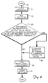
- FIG. 4 is a flow chart illustrating operation of a transmitter when adjustment is selected by an operator.
- FIG. 5 illustrates an adjusted electrical output responding to manual movement and time with a time rate increasing exponentially with time.
- a first embodiment of transmitter 50 includes sensing means 52 which sense process variable 54, such as pressure, temperature, flow, pH or the like.
- Sensing means 52 preferably includes a sensor and uses a microcomputer to control transmitter output 56 to represent sensed process variable 54.
- Transmitter output 56 preferably couples to a 4-20 mA current loop which energizes the transmitter, and transmitter output 56 controls the magnitude of the loop current to indicate the value of the process variable.
- Transmitter 50 can be adapted to a variety of applications with differing requirements to adjust upper (20 mA) and lower (4 mA) values of the transmitter output to process variables.
- transmitter 50 is a pressure transmitter and has a 20 mA output when the pressure is 100 PSI (700 kPa) and a 4 mA output when the pressure is 0 PSI (0 kPa).
- the same pressure transmitter 50 is required to have a 20 mA output when the pressure is 50 PSI (350 kPa) and a 4 mA output when the pressure is 30 psi (210 kPa).
- a manual adjustment of upper and lower range values of the output, or alternatively span and zero, is thus desired to adjust the transmitter to each application.
- adjustment means 58 receives manual adjustment 60 applied to potentiometer 62 or other manual input device such as an optical encoder. Adjustment means 58 converts manual adjustment 60 to adjusted electrical output 64.
- Manual adjustment 60 is divided into two ranges. In a fine range of manual adjustment, adjusted electrical output 64 varies responsive to changes in the position of manual adjustment 60 itself. This fine range provides for fine adjustment and is typically the middle range of travel of potentiometer 62 or other manual input device. In a coarse range of manual adjustment, adjusted electrical output 64 varies as function of time. The coarse range is typically near two ends of travel of potentiometer 62 or other manual input device.
- the adjusted electrical output increases with time near one end of travel of the potentiometer, and decreases with time near the other end of travel of the potentiometer.
- Various other arrangements of the coarse range of adjustment that is adjustment as a function of time, can be used.
- Speed of coarse adjustment with time can be fixed, made a function of the manual adjustment, or the speed can be a function of the length of time that the adjustment is left in the coarse range, as desired.
- Adjustment means 58 preferably includes a potentiometer 62 and an analog-to-digital converter to provide adjusted electrical output 64 as a digital word to a microcomputer in transmitter 50. Adjustment with time in the coarse range is preferably controlled by a microcomputer, as well.
- Adjusted electrical output 64 couples to storage means 66 and selection means 68 in transmitter 50.
- Storage means 66 comprises non-volatile memory, such as electrically erasable programmable read only memory (EEPROM), for storing one or more setting of adjusted electrical output 64, which correspond to span, zero, upper range value, lower range value settings, and the like.
- EEPROM electrically erasable programmable read only memory
- a value of adjusted electrical output 64 is stored for each selected adjustment when a corresponding STORE command 70 is applied to storage means 66.
- Storage means 66 provide a stored value 72 corresponding to each stored setting to selection means 68.
- Selection means 68 receives adjusted electrical output 64 and also stored value 72 (which can include multiple settings for multiple adjustments, such as both upper and lower range settings of the transmitter output).
- Manual selection input 74 which can be a switch setting on the transmitter controlled by an operator, couples to selection means 68 to control selection of the application of adjusted electrical output 64 and stored value 72 to selected output 76.
- Manual selection input 74 has a STORE position and a position for each desired setting (e.g., upper and lower range values of the transmitter output). When the operator moves manual selection input 74 to select the "store" position, selection means 68 provides a STORE command to storage means 66 to store a stored value for the last setting selected at manual input 74.
- the output 76 When manual selection input 74 rests in the store position, the output 76 comprises stored values of setting only, and does not comprise adjusted electrical output 64. When manual selection input 74 rests in the store position, the selected output 76 is independent of inadvertent actuation of potentiometer 62 by shock, vibration, or tampering. When manual selection input 74 is in a position to select a setting such as lower range value, for example, then the adjusted electrical output 64 is provided as that selected setting (lower range value) to selected output 76. Selected output 76 couples to sensing means 52 to provide setting for controlling conversion parameters of sensed process variable 54 to a value on output 56. Selection means 68 preferably is implemented in a microcomputer program.
- Sensing means 52 computes transmitter output 56 according to a selected equation which is a function of sensed process variable 54 and parameter settings received from selected output 76.
- the conversion equation is simply a straight line, or linear equation relating transmitter output 56 to sensed process variable 54 with scale factor and offset controlled by selected output 76.
- Other relationships between the transmitter output and the sensed process variable 54, such as a square root relationship can also be used.
- FIG. 2 a second embodiment of a transmitter according to the invention is shown.
- Sensor 10 senses a process variable such as pressure, temperature, flow, pH or the like.
- Sensor 10 generates an analog sensor output representative of the sensed process variable which couples to analog-to-digital (A/D) converter 11.
- A/D converter 11 converts the analog sensor output to a digital sensor output which couples to microcomputer 12.
- Microcomputer 12 includes nonvolatile memory 13 for storing adjustment settings and the like.
- Microcomputer 12 calculates a digital transmitter output as a function of the settings and the digital sensor output.
- the digital transmitter output couples to digital-to-analog (D/A) converter 14 which provides an analog transmitter control output to loop controller 15.
- D/A digital-to-analog
- Loop controller 15 connects to current loop 16 at terminals 17, 18 and controls current on loop 16 to have a magnitude representative of the sensed process variable.
- Loop 16 includes a resistor 21 and a DC power supply at terminals 19, 20 which are located remotely from the transmitter. A potential across resistor 21, that is between terminals 20,22 is representative of the sensed process variable.
- loop power supply at terminals 19, 20 energizes loop current controller 15.
- Loop current controller 15 in turn, energizes power supply 23 in the loop current controller which provides energization to all transmitter circuitry on lines 24, 25.
- potentiometer 26 receives manual adjustment from an operator and provides an analog voltage to microcomputer 12.
- Microcomputer 12 senses the analog voltage and generates an adjusted electrical output (a word which the microcomputer stores in random access memory, for example) which depends on the analog voltage being in a fine or coarse range of adjustment as determined by the microcomputer. If the analog voltage is in the fine range, the magnitude of the adjusted electrical output varies with the position of the manual adjustment itself received by the potentiometer 26. If the analog voltage is in a coarse range, the magnitude of the adjusted electrical output varies as a function of time.
- the fine range is the middle part of adjustment of the potentiometer and the coarse range includes parts of the adjustment of the potentiometer near both ends of adjustment.
- the potentiometer provides finer adjustment of the adjusted electrical output over its central portion, and coarser adjustment as a function of time near the ends of the potentiometer's travel.
- An operator can move the manual adjustment back and forth between the fine and coarse ranges until a desired transmitter output value is observed.
- the operator can manually actuate switch circuit 27 to store the desired transmitter output value in nonvolatile memory 13 as a upper range value or lower range value setting as desired.
- Switch circuit 27 has three positions, one for setting upper range value (typically 20 mA of loop current), one for setting lower range value (typically 4 mA of loop current), and one for initiating a STORE command to the nonvolatile memory.
- the transmitter upper and lower range value setting are not sensitive to movement of potentiometer 26 due to shock, vibration, and tampering.
- microcomputer 12 performs several functions.
- the microcomputer provides adjustment means for adjusting an adjusted electrical output as a function of sensed potentiometer position to adjust the adjusted electrical output as either a function of time or position depending on the range in which the adjustment input is sensed.
- the microcomputer includes nonvolatile storage means 13 for storing a stored value of a setting when the STORE command is initiated by switch 27.
- the microcomputer includes selection means for selecting either a stored value or the adjusted electrical output depending on position of the switch circuit 27.
- the microcomputer 12 generates the STORE signal responsive to movement of switch circuit 27 to the store position.
- the microcomputer computes the output as a function of the sensed process variable and the settings provided by the operator through switch 27 and potentiometer 26.
- adjusted electrical output 64 is illustrated responding to manual movement and time.
- An axis labeled "WIPER POSITION” represents mechanical position of a wiper of a potentiometer such as potentiometer 26 or 62.
- An axis labelled “OUTPUT” represents adjusted electrical output such as adjusted electrical output 64.
- FIG. 3 at 44 is a first illustration of response of the adjusted electrical output to an operator's movement of the potentiometer's wiper.
- the output In a central region of wiper travel, defined by dashed vertical lines, the output varies according to the wiper position itself. The variation in the central region shown at 44 is linear, however, more complex functions can be used as well.
- the output As the wiper is moved to the left of the central region, the output becomes less sensitive to wiper position as illustrated by the horizontal line.
- the output is dependent on time in that left region and the output decreases as a function of time as illustrated by the downward arrows.
- the arrows are all the same length illustrating that the time rate of change is substantially independent of wiper position.
- one aspect of the time rate of adjustment illustrated in FIG. 3 is that the manual adjustment may be inadvertently left with the adjusted electrical output changing as a function of time for an extended interval of time.
- a transmitter's output cannot continue to increase or decrease indefinitely, and eventually reaches some upper or lower limit, e. g., current saturation such as 3.5 mA or 25 mA in 4 to 20 mA transmitter output.
- some upper or lower limit e. g., current saturation such as 3.5 mA or 25 mA in 4 to 20 mA transmitter output.
- the transmitter compares the adjusted electrical output to a stored value, and if there is such a large discrepancy or difference between the transmitter output and the adjusted electrical output, the adjusted electrical output is automatically reset to the stored value as an initial setting. This operation automatically restores transmitter output current to a non-saturated range where change can be observed by the operator. This avoids long delays in making adjustments.
- the resetting operation is illustrated starting at 30 for an exemplary pressure transmitter.
- the operator first applies a reference, such a pressure corresponding to an upper range value to the pressure transmitter as shown at 31.
- the operator next sets the selector switch to upper range value as shown at 32.
- Setting the selector switch to upper range value is sensed by a microcomputer, and the microcomputer responds by performing the logical test shown at 33.
- a difference between the adjusted electrical output (initial output value) and the currently stored output value (stored value) is calculated. If the difference is less than a predetermined amount (disparity threshold), no resetting is done and calibration continues on as shown at 35.
- the adjusted electrical output (calibration parameter) is changed to near the current stored value as shown at 34.
- calibration continues as shown at 35.
- the operator makes fine and coarse adjustments as previously described above.
- the operator moves the selector switch to the "store" position as shown at 36 to store the new setting.
- a time limit is placed on the length of time that the adjusted electrical output 64 can change as a function of time without the position of the adjustment changing.
- the time limit is typically a 15 minutes. If the operator does not move the adjustment during this time limit, then the transmitter automatically leaves the adjustment mode.
- adjusted electrical output 64 is illustrated responding to manual movement and time.
- a first axis labelled “OUTPUT” represents a value of adjusted electrical output 64.
- An axis labelled “WIPER POSITION” represents position of a wiper of a potentiometer in a central region of wiper travel.
- Axes labelled “TIME” on opposite sides of the WIPER POSITION axis illustrate the length of time intervals when the wiper position of the potentiometer is outside the central region.
- Adjusted electrical output 64 has an initial value 80 shown in FIG. 5 when the wiper is in the central region. As an operator moves the wiper to the left as illustrated at 81, the value of the adjusted electrical output decreases as a function of the wiper position.
- the adjusted electrical output 64 When the wiper continues to move left, the wiper leaves the central region, and the adjusted electrical output 64 then has a value shown at 82 in FIG. 5.
- the values of the adjusted electrical output 64 at 81 and 82 are substantially the same value, however, because the wiper is outside the central region at 82, the output changes exponentially as a function of the length of time that the adjustment is left outside the central region.
- the exponential change as a function of time of adjusted electrical output 64 is illustrated at 83 in FIG. 5.
- An operator allows the adjusted electrical output 64 to change exponentially with time until the adjusted electrical output 64 is near a desired value at 84, and then the operator moves the wiper back into the central region where the adjusted electrical output again becomes a function of position as illustrated at 85.
- the operator can move the wiper from 80 to the right to increase the output as illustrated generally at 86.
- the exponential change with time provides a coarse adjustment, and the adjustment with position provides a fine adjustment.
- the exponential function is merely exemplary, and other functions wherein the time rate of change of the adjusted electrical output 64 increases with the length of time that the wiper is outside of the central region can also be used.
- Adjustments of transmitter outputs according to the present invention allows arbitrary selection of upper and lower transmitter output values. Rather than being limited to setting the output to 4 mA and 20 mA when lower and upper reference pressures are applied, the outputs can be set to other values arbitrarily within the operating limits of the transmitter. A lower value could be set at 8 mA and an upper value could be set at 12 mA, and the transmitter would then operate according to those settings over the entire 4-20 mA output range. The transmitter can thus be calibrated to operate over a selected range even when reference pressures are not available at the upper and lower limits of the range.
- Adjustments of transmitter output parameter settings according to the present invention can be made to not interact with one another, regardless of which adjustment is done first.
- the adjustments adjust parameters in an equation stored in the microprocessor, and the equation calculates the transmitter output.
- a preferred method of transmitter output adjustment can be performed using the above equation by providing a serial digital input to adjustment means 58 in FIG. 1.
- the serial digital input to adjustment means 58 adjusts the adjusted transmitter output 64 as a substitute for manual adjustment and setting.
- the transmitter can be automatically re -ranged after initial calibration.
- the calibration device provides a serial input to sensing means 52 to provide a substitute, simulated value of the process variable (NFN) to sensing means 52. While this substituted value is being provided, circuitry such as an application specific integrated circuit (ASIC) providing the actual pressure reading is disabled.
- ASIC application specific integrated circuit
- the calibration device then senses the transmitter output and, if adjustment is needed, sends an adjustment output to the serial digital input of adjustment means 58 to increment or decrement the adjusted electrical output 64 as needed until the transmitter output as sensed by the calibration device is at a desired setting.
- the adjustment is then stored in EEPROM in the transmitter as described above. This process is then repeated for another transmitter setting so that both span and zero can be automatically set. After the re-ranging is complete, the ASIC is re-enabled so that the output again represents pressure.
Landscapes
- Physics & Mathematics (AREA)
- General Physics & Mathematics (AREA)
- Engineering & Computer Science (AREA)
- Technology Law (AREA)
- Indication And Recording Devices For Special Purposes And Tariff Metering Devices (AREA)
- Transmitters (AREA)
- Arrangements For Transmission Of Measured Signals (AREA)
- Amplifiers (AREA)
Abstract
Description
- This invention relates to process variable transmitters having manually adjustable output parameters such as span, zero, or upper and lower range values.
- The present invention relates to a process variable transmitter which has manually adjustable settings, such as span and zero or upper and lower range values of the transmitter's output. Each manual adjustment can be set to a fine range where the transmitter output responds to changes in the manual adjustment itself to provide a fine adjustment of the transmitter output. The manual adjustment can then be set to a coarse range where the transmitter output changes automatically as a function of time to provide coarse adjustment. An operator can move the manual adjustment back and forth between the fine and coarse ranges until a desired transmitter output value is observed. When adjustment is thus complete, the operator can manually select the desired transmitter output value and then selection means in the transmitter provide a storage command to nonvolatile storage means in the transmitter to store the setting. After a setting is stored, the transmitter output is not sensitive to movement of the manual adjustment, but is instead controlled by the stored setting.
- Shock and vibration applied to the transmitter can move the adjustment setting, but do not affect the adjustment of the transmitter output once the settings are stored. The settings are not lost when energization is removed from the transmitter because the settings are stored in non-volatile memory.
- FIG. 1 is a block diagram of a first embodiment of a transmitter according to the invention.
- FIG. 2 is a block diagram of a second embodiment of a transmitter according to the invention.
- FIG. 3 illustrates an adjusted electrical output responding to manual movement and time with a time rate depending on wiper position.
- FIG. 4 is a flow chart illustrating operation of a transmitter when adjustment is selected by an operator.
- FIG. 5 illustrates an adjusted electrical output responding to manual movement and time with a time rate increasing exponentially with time.
- In FIG. 1, a first embodiment of
transmitter 50 includes sensing means 52 whichsense process variable 54, such as pressure, temperature, flow, pH or the like. Sensing means 52 preferably includes a sensor and uses a microcomputer to controltransmitter output 56 to representsensed process variable 54.Transmitter output 56 preferably couples to a 4-20 mA current loop which energizes the transmitter, andtransmitter output 56 controls the magnitude of the loop current to indicate the value of the process variable. -
Transmitter 50 can be adapted to a variety of applications with differing requirements to adjust upper (20 mA) and lower (4 mA) values of the transmitter output to process variables. In one exemplary application,transmitter 50 is a pressure transmitter and has a 20 mA output when the pressure is 100 PSI (700 kPa) and a 4 mA output when the pressure is 0 PSI (0 kPa). In another exemplary application, thesame pressure transmitter 50 is required to have a 20 mA output when the pressure is 50 PSI (350 kPa) and a 4 mA output when the pressure is 30 psi (210 kPa). A manual adjustment of upper and lower range values of the output, or alternatively span and zero, is thus desired to adjust the transmitter to each application. Likewise for other process variables and other types of transmitter outputs, there is a desire for manual adjustment locally at the transmitter. - In FIG. 1, adjustment means 58 receives
manual adjustment 60 applied topotentiometer 62 or other manual input device such as an optical encoder. Adjustment means 58 convertsmanual adjustment 60 to adjustedelectrical output 64.Manual adjustment 60 is divided into two ranges. In a fine range of manual adjustment, adjustedelectrical output 64 varies responsive to changes in the position ofmanual adjustment 60 itself. This fine range provides for fine adjustment and is typically the middle range of travel ofpotentiometer 62 or other manual input device. In a coarse range of manual adjustment, adjustedelectrical output 64 varies as function of time. The coarse range is typically near two ends of travel ofpotentiometer 62 or other manual input device. In one embodiment, the adjusted electrical output increases with time near one end of travel of the potentiometer, and decreases with time near the other end of travel of the potentiometer. Various other arrangements of the coarse range of adjustment, that is adjustment as a function of time, can be used. There can be a single coarse range in which the adjustedelectrical output 64 alternately varies up and down in a sawtooth pattern over the range of available transmitter output settings. Speed of coarse adjustment with time can be fixed, made a function of the manual adjustment, or the speed can be a function of the length of time that the adjustment is left in the coarse range, as desired. - Adjustment means 58 preferably includes a
potentiometer 62 and an analog-to-digital converter to provide adjustedelectrical output 64 as a digital word to a microcomputer intransmitter 50. Adjustment with time in the coarse range is preferably controlled by a microcomputer, as well. - Adjusted
electrical output 64 couples to storage means 66 and selection means 68 intransmitter 50. Storage means 66 comprises non-volatile memory, such as electrically erasable programmable read only memory (EEPROM), for storing one or more setting of adjustedelectrical output 64, which correspond to span, zero, upper range value, lower range value settings, and the like. A value of adjustedelectrical output 64 is stored for each selected adjustment when acorresponding STORE command 70 is applied to storage means 66. Storage means 66 provide astored value 72 corresponding to each stored setting to selection means 68. - Selection means 68 receives adjusted
electrical output 64 and also stored value 72 (which can include multiple settings for multiple adjustments, such as both upper and lower range settings of the transmitter output).Manual selection input 74, which can be a switch setting on the transmitter controlled by an operator, couples to selection means 68 to control selection of the application of adjustedelectrical output 64 andstored value 72 to selectedoutput 76.Manual selection input 74 has a STORE position and a position for each desired setting (e.g., upper and lower range values of the transmitter output). When the operator movesmanual selection input 74 to select the "store" position, selection means 68 provides a STORE command to storage means 66 to store a stored value for the last setting selected atmanual input 74. Whenmanual selection input 74 rests in the store position, theoutput 76 comprises stored values of setting only, and does not comprise adjustedelectrical output 64. Whenmanual selection input 74 rests in the store position, theselected output 76 is independent of inadvertent actuation ofpotentiometer 62 by shock, vibration, or tampering. Whenmanual selection input 74 is in a position to select a setting such as lower range value, for example, then the adjustedelectrical output 64 is provided as that selected setting (lower range value) to selectedoutput 76. Selectedoutput 76 couples to sensing means 52 to provide setting for controlling conversion parameters ofsensed process variable 54 to a value onoutput 56. Selection means 68 preferably is implemented in a microcomputer program. - Sensing means 52
computes transmitter output 56 according to a selected equation which is a function ofsensed process variable 54 and parameter settings received fromselected output 76. Typically, the conversion equation is simply a straight line, or linear equation relatingtransmitter output 56 to sensedprocess variable 54 with scale factor and offset controlled byselected output 76. Other relationships between the transmitter output and thesensed process variable 54, such as a square root relationship can also be used. - In FIG. 2, a second embodiment of a transmitter according to the invention is shown.
Sensor 10 senses a process variable such as pressure, temperature, flow, pH or the like.Sensor 10 generates an analog sensor output representative of the sensed process variable which couples to analog-to-digital (A/D) converter 11. A/D converter 11 converts the analog sensor output to a digital sensor output which couples tomicrocomputer 12.Microcomputer 12 includesnonvolatile memory 13 for storing adjustment settings and the like.Microcomputer 12 calculates a digital transmitter output as a function of the settings and the digital sensor output. The digital transmitter output couples to digital-to-analog (D/A)converter 14 which provides an analog transmitter control output toloop controller 15.Loop controller 15 connects tocurrent loop 16 atterminals loop 16 to have a magnitude representative of the sensed process variable.Loop 16 includes aresistor 21 and a DC power supply atterminals 19, 20 which are located remotely from the transmitter. A potential acrossresistor 21, that is betweenterminals 20,22 is representative of the sensed process variable. - The loop power supply at
terminals 19, 20 energizes loopcurrent controller 15. Loopcurrent controller 15, in turn, energizespower supply 23 in the loop current controller which provides energization to all transmitter circuitry onlines 24, 25. - In FIG. 2,
potentiometer 26 receives manual adjustment from an operator and provides an analog voltage tomicrocomputer 12.Microcomputer 12 senses the analog voltage and generates an adjusted electrical output (a word which the microcomputer stores in random access memory, for example) which depends on the analog voltage being in a fine or coarse range of adjustment as determined by the microcomputer. If the analog voltage is in the fine range, the magnitude of the adjusted electrical output varies with the position of the manual adjustment itself received by thepotentiometer 26. If the analog voltage is in a coarse range, the magnitude of the adjusted electrical output varies as a function of time. Preferably, the fine range is the middle part of adjustment of the potentiometer and the coarse range includes parts of the adjustment of the potentiometer near both ends of adjustment. - In a preferred embodiment, the potentiometer provides finer adjustment of the adjusted electrical output over its central portion, and coarser adjustment as a function of time near the ends of the potentiometer's travel. An operator can move the manual adjustment back and forth between the fine and coarse ranges until a desired transmitter output value is observed. When adjustment is complete, the operator can manually actuate
switch circuit 27 to store the desired transmitter output value innonvolatile memory 13 as a upper range value or lower range value setting as desired.Switch circuit 27 has three positions, one for setting upper range value (typically 20 mA of loop current), one for setting lower range value (typically 4 mA of loop current), and one for initiating a STORE command to the nonvolatile memory. Whenswitch circuit 27 is in the "store" position, the transmitter upper and lower range value setting are not sensitive to movement ofpotentiometer 26 due to shock, vibration, and tampering. - In FIG. 2,
microcomputer 12 performs several functions. The microcomputer provides adjustment means for adjusting an adjusted electrical output as a function of sensed potentiometer position to adjust the adjusted electrical output as either a function of time or position depending on the range in which the adjustment input is sensed. The microcomputer includes nonvolatile storage means 13 for storing a stored value of a setting when the STORE command is initiated byswitch 27. The microcomputer includes selection means for selecting either a stored value or the adjusted electrical output depending on position of theswitch circuit 27. Themicrocomputer 12 generates the STORE signal responsive to movement ofswitch circuit 27 to the store position. The microcomputer computes the output as a function of the sensed process variable and the settings provided by the operator throughswitch 27 andpotentiometer 26. - In FIG. 3, adjusted
electrical output 64 is illustrated responding to manual movement and time. An axis labeled "WIPER POSITION" represents mechanical position of a wiper of a potentiometer such aspotentiometer electrical output 64. - In FIG. 3 at 44 is a first illustration of response of the adjusted electrical output to an operator's movement of the potentiometer's wiper. In a central region of wiper travel, defined by dashed vertical lines, the output varies according to the wiper position itself. The variation in the central region shown at 44 is linear, however, more complex functions can be used as well. As the wiper is moved to the left of the central region, the output becomes less sensitive to wiper position as illustrated by the horizontal line. The output is dependent on time in that left region and the output decreases as a function of time as illustrated by the downward arrows. The arrows are all the same length illustrating that the time rate of change is substantially independent of wiper position. On the right side of the central region at 44 is another region of wiper position where the output increases with time at a fixed rated. The operator can thus cause large, coarse excursions of the output by simply leaving the wiper to the left or right of the central region. Once the output has moved close to the value desired by the operator, the operator can move the wiper to the central region to make fine adjustments. This arrangement allows the potentiometer's limited resolution to be confined to a relatively small but movable range. The result is availability of high resolution adjustment over the entire range of settings made available by the transmitter.
- In FIG. 3 at 44', an alternate arrangement similar to that shown at 44 is illustrated, however, the magnitude of the time rate of change is adjusted by the wiper position. This allow the operator to move quickly to a desired general adjustment range, and then move the wiper to slow down the time rate of adjustment as the desired setting is approached, and then finally move smoothly into the central region to complete a fine adjustment before storing the adjustment.
- Turning next to FIG. 4, one aspect of the time rate of adjustment illustrated in FIG. 3 is that the manual adjustment may be inadvertently left with the adjusted electrical output changing as a function of time for an extended interval of time. A transmitter's output cannot continue to increase or decrease indefinitely, and eventually reaches some upper or lower limit, e. g., current saturation such as 3.5 mA or 25 mA in 4 to 20 mA transmitter output. When this limit is reached by the transmitter's output, but exceeded by the adjusted electrical output, the transmitter's output does not respond immediately to further changes in the position of the wiper and the adjustment appears to the operator to be not operating. When the operator returns to make a desired adjustment, it can take an undesirably long wait to bring the output back to a desired setting. In a preferred embodiment illustrated in a flow chart, FIG. 4, the transmitter compares the adjusted electrical output to a stored value, and if there is such a large discrepancy or difference between the transmitter output and the adjusted electrical output, the adjusted electrical output is automatically reset to the stored value as an initial setting. This operation automatically restores transmitter output current to a non-saturated range where change can be observed by the operator. This avoids long delays in making adjustments.
- In FIG. 4, the resetting operation is illustrated starting at 30 for an exemplary pressure transmitter. The operator first applies a reference, such a pressure corresponding to an upper range value to the pressure transmitter as shown at 31. The operator next sets the selector switch to upper range value as shown at 32. Setting the selector switch to upper range value is sensed by a microcomputer, and the microcomputer responds by performing the logical test shown at 33. At 33, a difference between the adjusted electrical output (initial output value) and the currently stored output value (stored value) is calculated. If the difference is less than a predetermined amount (disparity threshold), no resetting is done and calibration continues on as shown at 35. If, however, the difference exceeds the disparity threshold, then the adjusted electrical output (calibration parameter) is changed to near the current stored value as shown at 34. After the change shown at 34, calibration continues as shown at 35. At 35, the operator makes fine and coarse adjustments as previously described above. After adjustment is complete, the operator moves the selector switch to the "store" position as shown at 36 to store the new setting.
- The procedure illustrated in FIG. 4 can be repeated for other setting as desired. In a further improvement, a time limit is placed on the length of time that the adjusted
electrical output 64 can change as a function of time without the position of the adjustment changing. The time limit is typically a 15 minutes. If the operator does not move the adjustment during this time limit, then the transmitter automatically leaves the adjustment mode. - In FIG. 5, adjusted
electrical output 64 is illustrated responding to manual movement and time. A first axis labelled "OUTPUT" represents a value of adjustedelectrical output 64. An axis labelled "WIPER POSITION" represents position of a wiper of a potentiometer in a central region of wiper travel. Axes labelled "TIME" on opposite sides of the WIPER POSITION axis illustrate the length of time intervals when the wiper position of the potentiometer is outside the central region. Adjustedelectrical output 64 has aninitial value 80 shown in FIG. 5 when the wiper is in the central region. As an operator moves the wiper to the left as illustrated at 81, the value of the adjusted electrical output decreases as a function of the wiper position. When the wiper continues to move left, the wiper leaves the central region, and the adjustedelectrical output 64 then has a value shown at 82 in FIG. 5. The values of the adjustedelectrical output 64 at 81 and 82 are substantially the same value, however, because the wiper is outside the central region at 82, the output changes exponentially as a function of the length of time that the adjustment is left outside the central region. The exponential change as a function of time of adjustedelectrical output 64 is illustrated at 83 in FIG. 5. An operator allows the adjustedelectrical output 64 to change exponentially with time until the adjustedelectrical output 64 is near a desired value at 84, and then the operator moves the wiper back into the central region where the adjusted electrical output again becomes a function of position as illustrated at 85. - Alternatively in FIG. 5, the operator can move the wiper from 80 to the right to increase the output as illustrated generally at 86. The exponential change with time provides a coarse adjustment, and the adjustment with position provides a fine adjustment. The exponential function is merely exemplary, and other functions wherein the time rate of change of the adjusted
electrical output 64 increases with the length of time that the wiper is outside of the central region can also be used. - Adjustments of transmitter outputs according to the present invention allows arbitrary selection of upper and lower transmitter output values. Rather than being limited to setting the output to 4 mA and 20 mA when lower and upper reference pressures are applied, the outputs can be set to other values arbitrarily within the operating limits of the transmitter. A lower value could be set at 8 mA and an upper value could be set at 12 mA, and the transmitter would then operate according to those settings over the entire 4-20 mA output range. The transmitter can thus be calibrated to operate over a selected range even when reference pressures are not available at the upper and lower limits of the range.
- Adjustments of transmitter output parameter settings according to the present invention can be made to not interact with one another, regardless of which adjustment is done first. The adjustments adjust parameters in an equation stored in the microprocessor, and the equation calculates the transmitter output. A preferred method of noninteractive span and zero adjustment is represented by the following equation:

- DACOUT represents the transmitter output;
- NFN represents a linearized, filtered value of the sensed process variable;
- SET4 represents a zero setting;
- SPAN represents a span setting;
- SHIFT represents an exponent adjusted to keep calculated values such as SPAN/2shift within a convenient calculation range of a microprocessor;
- MINVAL represents a output value of the transmitter output at the last zero setting.
- A preferred method of transmitter output adjustment can be performed using the above equation by providing a serial digital input to adjustment means 58 in FIG. 1. The serial digital input to adjustment means 58 adjusts the adjusted
transmitter output 64 as a substitute for manual adjustment and setting. By using a calibration device which monitorstransmitter output 56 and feeds back digital adjustments and settings to the serial digital input of adjustment means 58, the transmitter can be automatically re -ranged after initial calibration. As a first step in such automatic re-ranging, the calibration device provides a serial input to sensing means 52 to provide a substitute, simulated value of the process variable (NFN) to sensing means 52. While this substituted value is being provided, circuitry such as an application specific integrated circuit (ASIC) providing the actual pressure reading is disabled. The calibration device then senses the transmitter output and, if adjustment is needed, sends an adjustment output to the serial digital input of adjustment means 58 to increment or decrement the adjustedelectrical output 64 as needed until the transmitter output as sensed by the calibration device is at a desired setting. The adjustment is then stored in EEPROM in the transmitter as described above. This process is then repeated for another transmitter setting so that both span and zero can be automatically set. After the re-ranging is complete, the ASIC is re-enabled so that the output again represents pressure.
Claims (17)
- A transmitter (50), comprising:manual adjustment means (58,60) which is manually controllable (60) by an operator for providing both fine range and coarse range adjustments (62) of an adjusted electrical output (64), the adjusted electrical output (64) adjusting in response to manual inputs (60) in the fine range and adjusting at a time rate of change automatically in the coarse range;storage means (13,66) for storing the adjusted electrical output in nonvolatile memory (13) as a stored value when a store command is received;selection means (68) receiving manual selections (74) from the operator, for selecting the adjusted electrical output (64) after the operator activates a desired setting and for providing the store command and selecting the stored value after occurrence of a predetermined event; andcircuit means (52) sensing a process variable (54) for controlling a transmitter output (56) which represents the process variable (54) and which has a parameter controlled by the selection such that the parameter can be adjusted coarsely and finely and made insensitive to adjustment by the storing.
- The transmitter of claim 1 wherein a total range of adjustment (60) includes a first portion selectable by the operator, where the adjusted electrical output (64) increases automatically with time and a second portion selectable by the operator, where the adjusted electrical output (64) decreases automatically with time.
- The transmitter of claim 2 wherein the time rate of change changes as a function of a time interval during which the operator leaves the manual adjustment means (58,60) in one of the two portions.
- The transmitter of claim 2 wherein the time rate of change changes as a function of the time interval such that the adjusted electrical output changes exponentially as a function of time.
- The transmitter of any one of the preceding claims wherein the circuit means (52) provides a transmitter output (56) limited to a transmitter output range and the fine range provides fine adjustment over a portion of the transmitter output range, and the coarse range provides coarse placement of the fine adjustment within the total range of adjustment.
- The transmitter of any one of the preceding claims wherein the time rate of change is a function of position of the manual adjustment means (58,60).
- The transmitter of any one of the preceding claims, wherein the adjusted electrical output includes a zero setting of the transmitter output.
- The transmitter of any one of the preceding claims wherein the adjusted electrical output includes a span setting of the transmitter output.
- The transmitter of any one of the preceding claims wherein the coarse range provides an adjusted electrical output which alternately increases and decreases automatically with time.
- The transmitter of any one of the preceding claims wherein the predetermined event occurs after the operator selects a store setting.
- The transmitter of claim 10 wherein the predetermined event occurs after absence of manual selections and manual inputs (60) for a predetermined time period
- The transmitter of any one of the preceding claims wherein the adjusted electrical output includes a lower range value setting of the transmitter output.
- The transmitter of any one of the preceding claims wherein the adjusted electrical output includes an upper range value setting of the transmitter output.
- The transmitter of any one of the preceding claims wherein the circuit means has first and second parameters controlled non-interactively by the selection means.
- The transmitter of claim 14 wherein the first and second parameters are terms SPAN and SET4 in an equation controlling the transmitter output substantially according to the equation:

- The transmitter of any one of the preceding claims wherein the transmitter includes resetting means for subtracting the transmitter output value from the stored value to compute a difference, the resetting means resetting the stored value to substantially the transmitter output value when the difference exceeds a predetermined discrepancy limit stored in the resetting means.
- The transmitter of any one of the preceding claims wherein the transmitter includes re-ranging means for receiving digital inputs from an external source and adjusting the adjusted electrical output as a function of the received digital input.
Applications Claiming Priority (3)
| Application Number | Priority Date | Filing Date | Title |
|---|---|---|---|
| US60317390A | 1990-10-25 | 1990-10-25 | |
| US603173 | 1990-10-25 | ||
| PCT/US1991/007866 WO1992008279A2 (en) | 1990-10-25 | 1991-10-24 | Transmitter with multifunction adjustment |
Publications (3)
| Publication Number | Publication Date |
|---|---|
| EP0554399A1 EP0554399A1 (en) | 1993-08-11 |
| EP0554399A4 EP0554399A4 (en) | 1993-11-03 |
| EP0554399B1 true EP0554399B1 (en) | 1996-01-31 |
Family
ID=24414375
Family Applications (1)
| Application Number | Title | Priority Date | Filing Date |
|---|---|---|---|
| EP92900369A Expired - Lifetime EP0554399B1 (en) | 1990-10-25 | 1991-10-24 | Transmitter with multifunction adjustment |
Country Status (8)
| Country | Link |
|---|---|
| EP (1) | EP0554399B1 (en) |
| JP (1) | JPH06502722A (en) |
| CN (1) | CN1028902C (en) |
| BR (1) | BR9106869A (en) |
| CA (1) | CA2093529A1 (en) |
| DE (1) | DE69116888T2 (en) |
| RU (1) | RU2125711C1 (en) |
| WO (1) | WO1992008279A2 (en) |
Families Citing this family (8)
| Publication number | Priority date | Publication date | Assignee | Title |
|---|---|---|---|---|
| FR2704342B1 (en) * | 1993-04-22 | 1995-06-23 | Sagem | INDICATOR WITH MOBILE DISPLAY AND ADJUSTABLE SENSITIVITY. |
| FI963031A7 (en) * | 1996-07-31 | 1998-02-01 | Nokia Telecommunications Oy | Linearization of a mobile station transmitter |
| DE19844663C2 (en) * | 1998-09-29 | 2000-09-21 | Siemens Ag | Circuit arrangement and method for setting switching points of a decision maker |
| RU2199088C1 (en) * | 2002-04-11 | 2003-02-20 | ООО "НТ-Центр" | Method for correcting static characteristics of measuring transducers |
| RU2199089C1 (en) * | 2002-04-11 | 2003-02-20 | ООО "НТ-Центр" | Method for correcting static characteristics of measuring transducers |
| US7223014B2 (en) * | 2003-03-28 | 2007-05-29 | Intempco Controls Ltd. | Remotely programmable integrated sensor transmitter |
| US9075029B2 (en) * | 2011-01-31 | 2015-07-07 | Scott Technologies, Inc. | System and method for automatically adjusting gas sensor settings and parameters |
| WO2016194610A1 (en) * | 2015-06-02 | 2016-12-08 | 株式会社バルコム | Measurement instrument having output signal adjusting function |
Family Cites Families (10)
| Publication number | Priority date | Publication date | Assignee | Title |
|---|---|---|---|---|
| DE1169692B (en) * | 1959-09-21 | 1964-05-06 | Fritz Hellige & Co G M B H Fab | Device for calibration or standard value marking in measuring and recording devices with at least two sensitivity ranges and at least two different fixed calibration or standard values adapted to these |
| DE1463283B2 (en) * | 1964-05-15 | 1971-10-28 | DIGITAL CONTROL OF THE MOVEMENT OF MACHINERY AND APPARATUS PART IN PARTICULAR THE MOVING ORGANS OF ROENTGEN DIFFRAKTOMETERS | |
| US3378741A (en) * | 1964-09-18 | 1968-04-16 | Ibm | Digital coarse and fine stepping motor control using an encoder for coarse position |
| US3544970A (en) * | 1967-12-12 | 1970-12-01 | American Mach & Foundry | Calibration of multiple channel electronic systems |
| JPS5829096A (en) * | 1981-08-13 | 1983-02-21 | 株式会社東芝 | Process variable transmitter |
| US4494183A (en) * | 1982-06-17 | 1985-01-15 | Honeywell Inc. | Process variable transmitter having a non-interacting operating range adjustment |
| US4783659A (en) * | 1986-08-22 | 1988-11-08 | Rosemount Inc. | Analog transducer circuit with digital control |
| US4748852A (en) * | 1986-10-10 | 1988-06-07 | Rosemount Inc. | Transmitter with an improved span adjustment |
| US4922856A (en) * | 1987-05-15 | 1990-05-08 | Sweeney Enterprises, Inc. | Vibrationally activated control apparatus for detecting signals from fish to enable demand feeding |
| US4818994A (en) * | 1987-10-22 | 1989-04-04 | Rosemount Inc. | Transmitter with internal serial bus |
-
1991
- 1991-10-24 BR BR9106869A patent/BR9106869A/en not_active IP Right Cessation
- 1991-10-24 CA CA002093529A patent/CA2093529A1/en not_active Abandoned
- 1991-10-24 DE DE69116888T patent/DE69116888T2/en not_active Expired - Fee Related
- 1991-10-24 CN CN 91109850 patent/CN1028902C/en not_active Expired - Fee Related
- 1991-10-24 EP EP92900369A patent/EP0554399B1/en not_active Expired - Lifetime
- 1991-10-24 WO PCT/US1991/007866 patent/WO1992008279A2/en not_active Ceased
- 1991-10-24 RU RU93044228A patent/RU2125711C1/en active
- 1991-10-24 JP JP4501260A patent/JPH06502722A/en active Pending
Also Published As
| Publication number | Publication date |
|---|---|
| RU2125711C1 (en) | 1999-01-27 |
| DE69116888T2 (en) | 1996-09-05 |
| BR9106869A (en) | 1994-06-14 |
| DE69116888D1 (en) | 1996-03-14 |
| CN1028902C (en) | 1995-06-14 |
| CA2093529A1 (en) | 1992-04-26 |
| WO1992008279A2 (en) | 1992-05-14 |
| EP0554399A4 (en) | 1993-11-03 |
| JPH06502722A (en) | 1994-03-24 |
| EP0554399A1 (en) | 1993-08-11 |
| CN1061091A (en) | 1992-05-13 |
| WO1992008279A3 (en) | 1992-06-25 |
Similar Documents
| Publication | Publication Date | Title |
|---|---|---|
| EP0097479B1 (en) | Adjustable process variable transmitter | |
| US5253511A (en) | Transmitter with multifunction adjustment | |
| US5253564A (en) | Conveyor oven control | |
| US5197375A (en) | Conveyor oven control | |
| US6149071A (en) | Flow control system for spray applications | |
| US5259252A (en) | Apparatus for measuring forces on a fishing rod | |
| JP4819274B2 (en) | Electronic mixed water preparation device and mixed water preparation method | |
| US4411649A (en) | Fluid flow control system | |
| EP0254843A2 (en) | Method and apparatus for automatic offset compensation in parameter-sensing transducer systems | |
| US5065172A (en) | Zoom lens camera | |
| AU669834B2 (en) | Automatic tuning of a position control circuit for a servo device | |
| WO1992008279A2 (en) | Transmitter with multifunction adjustment | |
| US5621398A (en) | Programmable switch | |
| CA1310127C (en) | Potentiometer setting detection by measuring the ratio of rc time constants | |
| US4412591A (en) | Method and apparatus for selecting operating modes or parameters in an electrical scale | |
| EP0131461B1 (en) | Span adjustment in electronic weighing apparatus | |
| AU593722B2 (en) | Auto calibrating electro-hydraulic servo driver | |
| DE3032390A1 (en) | ELECTRIC WATCH THERMOSTAT | |
| US5408591A (en) | Automatic calibration and servo control scheme for offsetting mechanical and electronic component variances | |
| JPH07244534A (en) | Method for parameterizing a digital voltage regulator, in particular for regulating a transformer with a load tap changer | |
| EP0527467A2 (en) | Setup-setback thermostat having a simple setup-setback visual indicator | |
| US6809531B2 (en) | Digital potentiometer device | |
| WO1997001809A1 (en) | Direct load current sensing for predicted regulator tap position | |
| EP0775339B1 (en) | Current-to-pressure transducer with selectable, adjustable input filter | |
| US2782993A (en) | Automatic control system with remote adjustment |
Legal Events
| Date | Code | Title | Description |
|---|---|---|---|
| PUAI | Public reference made under article 153(3) epc to a published international application that has entered the european phase |
Free format text: ORIGINAL CODE: 0009012 |
|
| 17P | Request for examination filed |
Effective date: 19930329 |
|
| AK | Designated contracting states |
Kind code of ref document: A1 Designated state(s): DE FR GB NL SE |
|
| A4 | Supplementary search report drawn up and despatched |
Effective date: 19930910 |
|
| AK | Designated contracting states |
Kind code of ref document: A4 Designated state(s): DE FR GB NL SE |
|
| 17Q | First examination report despatched |
Effective date: 19941017 |
|
| GRAA | (expected) grant |
Free format text: ORIGINAL CODE: 0009210 |
|
| AK | Designated contracting states |
Kind code of ref document: B1 Designated state(s): DE FR GB NL SE |
|
| REF | Corresponds to: |
Ref document number: 69116888 Country of ref document: DE Date of ref document: 19960314 |
|
| ET | Fr: translation filed | ||
| PLBE | No opposition filed within time limit |
Free format text: ORIGINAL CODE: 0009261 |
|
| STAA | Information on the status of an ep patent application or granted ep patent |
Free format text: STATUS: NO OPPOSITION FILED WITHIN TIME LIMIT |
|
| 26N | No opposition filed | ||
| PGFP | Annual fee paid to national office [announced via postgrant information from national office to epo] |
Ref country code: FR Payment date: 19990930 Year of fee payment: 9 |
|
| PGFP | Annual fee paid to national office [announced via postgrant information from national office to epo] |
Ref country code: SE Payment date: 19991001 Year of fee payment: 9 |
|
| PGFP | Annual fee paid to national office [announced via postgrant information from national office to epo] |
Ref country code: NL Payment date: 19991007 Year of fee payment: 9 |
|
| PG25 | Lapsed in a contracting state [announced via postgrant information from national office to epo] |
Ref country code: SE Free format text: THE PATENT HAS BEEN ANNULLED BY A DECISION OF A NATIONAL AUTHORITY Effective date: 20001030 |
|
| PG25 | Lapsed in a contracting state [announced via postgrant information from national office to epo] |
Ref country code: NL Free format text: LAPSE BECAUSE OF NON-PAYMENT OF DUE FEES Effective date: 20010501 |
|
| EUG | Se: european patent has lapsed |
Ref document number: 92900369.7 |
|
| PG25 | Lapsed in a contracting state [announced via postgrant information from national office to epo] |
Ref country code: FR Free format text: LAPSE BECAUSE OF NON-PAYMENT OF DUE FEES Effective date: 20010629 |
|
| NLV4 | Nl: lapsed or anulled due to non-payment of the annual fee |
Effective date: 20010501 |
|
| REG | Reference to a national code |
Ref country code: FR Ref legal event code: ST |
|
| REG | Reference to a national code |
Ref country code: GB Ref legal event code: IF02 |
|
| PGFP | Annual fee paid to national office [announced via postgrant information from national office to epo] |
Ref country code: GB Payment date: 20041229 Year of fee payment: 14 |
|
| PG25 | Lapsed in a contracting state [announced via postgrant information from national office to epo] |
Ref country code: GB Free format text: LAPSE BECAUSE OF NON-PAYMENT OF DUE FEES Effective date: 20051024 |
|
| GBPC | Gb: european patent ceased through non-payment of renewal fee |
Effective date: 20051024 |
|
| PGFP | Annual fee paid to national office [announced via postgrant information from national office to epo] |
Ref country code: DE Payment date: 20081201 Year of fee payment: 18 |
|
| PG25 | Lapsed in a contracting state [announced via postgrant information from national office to epo] |
Ref country code: DE Free format text: LAPSE BECAUSE OF NON-PAYMENT OF DUE FEES Effective date: 20100501 |