EP0552860B1 - Device for controlling or limiting temperature in an electric cooking appliance - Google Patents
Device for controlling or limiting temperature in an electric cooking appliance Download PDFInfo
- Publication number
- EP0552860B1 EP0552860B1 EP93300013A EP93300013A EP0552860B1 EP 0552860 B1 EP0552860 B1 EP 0552860B1 EP 93300013 A EP93300013 A EP 93300013A EP 93300013 A EP93300013 A EP 93300013A EP 0552860 B1 EP0552860 B1 EP 0552860B1
- Authority
- EP
- European Patent Office
- Prior art keywords
- thermal expansion
- coefficient
- tube
- rod
- tube portions
- Prior art date
- Legal status (The legal status is an assumption and is not a legal conclusion. Google has not performed a legal analysis and makes no representation as to the accuracy of the status listed.)
- Expired - Lifetime
Links
Images

Classifications
-
- H—ELECTRICITY
- H05—ELECTRIC TECHNIQUES NOT OTHERWISE PROVIDED FOR
- H05B—ELECTRIC HEATING; ELECTRIC LIGHT SOURCES NOT OTHERWISE PROVIDED FOR; CIRCUIT ARRANGEMENTS FOR ELECTRIC LIGHT SOURCES, IN GENERAL
- H05B1/00—Details of electric heating devices
- H05B1/02—Automatic switching arrangements specially adapted to apparatus ; Control of heating devices
- H05B1/0202—Switches
- H05B1/0216—Switches actuated by the expansion of a solid element, e.g. wire or rod
-
- H—ELECTRICITY
- H05—ELECTRIC TECHNIQUES NOT OTHERWISE PROVIDED FOR
- H05B—ELECTRIC HEATING; ELECTRIC LIGHT SOURCES NOT OTHERWISE PROVIDED FOR; CIRCUIT ARRANGEMENTS FOR ELECTRIC LIGHT SOURCES, IN GENERAL
- H05B3/00—Ohmic-resistance heating
- H05B3/68—Heating arrangements specially adapted for cooking plates or analogous hot-plates
- H05B3/74—Non-metallic plates, e.g. vitroceramic, ceramic or glassceramic hobs, also including power or control circuits
- H05B3/746—Protection, e.g. overheat cutoff, hot plate indicator
-
- H—ELECTRICITY
- H01—ELECTRIC ELEMENTS
- H01H—ELECTRIC SWITCHES; RELAYS; SELECTORS; EMERGENCY PROTECTIVE DEVICES
- H01H37/00—Thermally-actuated switches
- H01H37/02—Details
- H01H37/32—Thermally-sensitive members
- H01H37/46—Thermally-sensitive members actuated due to expansion or contraction of a solid
- H01H37/48—Thermally-sensitive members actuated due to expansion or contraction of a solid with extensible rigid rods or tubes
-
- H—ELECTRICITY
- H05—ELECTRIC TECHNIQUES NOT OTHERWISE PROVIDED FOR
- H05B—ELECTRIC HEATING; ELECTRIC LIGHT SOURCES NOT OTHERWISE PROVIDED FOR; CIRCUIT ARRANGEMENTS FOR ELECTRIC LIGHT SOURCES, IN GENERAL
- H05B2213/00—Aspects relating both to resistive heating and to induction heating, covered by H05B3/00 and H05B6/00
- H05B2213/04—Heating plates with overheat protection means
Definitions
- the present invention relates to a device for controlling or limiting temperature in an electric cooking appliance and may be used, for example, in conjunction with an electric radiant heater having at least two heating elements to control or limit the temperature of a cooking surface of glass ceramic or the like in an electric cooking appliance.
- Such temperature control devices are known in conjunction with radiant heaters installed in glass ceramic top cookers.
- the devices typically incorporate a rod-like temperature sensor that operates on the basis of a difference in thermal expansion coefficients between an expansion member of the sensor and a reference member of the sensor.
- the difference in thermal expansion gives rise to differential movement which, in turn, is employed to operate one or more switches which are used, for example, to limit the temperature of the glass ceramic cooking surface and/or to indicate that the surface of the glass ceramic may be too hot to be touched.
- the temperature sensor generally comprises a rod of high expansion material located coaxially within a tube of low expansion material such as quartz (more correctly known as fused silica).
- the temperature sensor may comprise a rod of low expansion material located coaxially within a tube of high expansion material.
- At least two heating elements are incorporated in the radiant heater it is known, for example from GB-A-2 069 300, to isolate the temperature sensor from the heating effect of all except one of the heating elements.
- This can be achieved by enclosing part of the temperature sensor in a thermal insulation material or in a thermally conductive material which transmits the heat away to a heat sink, or by limiting the effective length of the temperature sensor to that part which extends over the relevant heating element.
- This latter means for isolating the temperature sensor can be put into effect by connecting part of the temperature sensor across the heating elements from which it is to be isolated in a manner which precludes those heating elements from influencing the response given by the sensor.
- GB-A-2 080 660 also discloses a radiant heater having at least two heating elements wherein the temperature sensor is isolated from the heating effect of all but one of the heating elements. According to GB-A-2 080 660 this is achieved by extending the heating effect of the one heating element so as to influence substantially the entire effective length of the temperature sensor.
- GB-A-2 133 879 discloses means for isolating part of the temperature sensor from heat emitted by the heating elements of a radiant heater.
- the temperature sensor comprises a rod of high thermal expansion material arranged coaxially within a tube which is assembled from at least two tubular sections.
- the tubular sections have different thermal expansions such that the overall thermal expansion of the whole tube is less than the thermal expansion of the rod.
- the rod is made of an iron-chromium alloy
- one of the tubular sections is made of quartz glass or ceramic material and the other tubular section is made of the same material as the rod.
- the drawback is that the tubular section or sections where the temperature sensor is isolated are made of a relatively expensive material which requires to be machined to the required tubular shape. Additionally, because one or more of the tubular sections is or are made of metal and reduces the electrical clearance distance between the electrically live heating coil and the underside of the glass ceramic cooking surface, it is necessary electrically to insulate the metal section. This is achieved by surrounding the metal section with a tube of electrically insulating material, such as quartz glass or other ceramic material, which adds to the cost of the temperature control device. The result is that the temperature control device is not economic to manufacture.
- EP-A-0 141 923 also discloses means for isolating part of the temperature sensor.
- the temperature sensor comprises a tube of high thermal expansion material such as high-quality steel having arranged therein a rod made of at least two sections.
- One of the rod sections is made of a ceramic material, but the remaining section or sections are made of a material having a coefficient of thermal expansion at least as high, and preferably higher than that of the tube, thus providing a form of over-compensation in the response of the sensor to variations in temperature.
- the metal tube it is necessary to provide a further tube of quartz glass around the entire length of the metal tube.
- Such a temperature sensor has the disadvantage that the further tube acts as a heat sink and causes the temperature response of the sensor to lag behind the actual temperature. Moreover, the further tube constitutes an additional component which adds to the cost of the temperature control device and renders it uneconomic to manufacture.
- EP-A-0 279 368 describes a temperature limiter in which the inner rod of the temperature sensor having the greater expansion coefficient comprises at least two longitudinally connected portions, which with respect to their length, cross-section and expansion action are matched to different zones of a heater so that one or more zones do not, or only slightly, influence the temperature value sensed by the sensor, whereas one or more further zones substantially influence the sensed value.
- EP-A-0 279 368 it is also conceivable to subdivide the outer tube in a corresponding manner. There is no disclosure as to the nature of the materials of such a subdivided outer tube.
- a device for controlling or limiting temperature in an electric cooking appliance comprising switch means and a temperature sensor operatively coupled to the switch means, the temperature sensor comprising a rod arranged substantially coaxially within a tube, the rod being made of a material having a first coefficient of thermal expansion and the tube comprising at least two tube portions having different coefficients of thermal expansion such that the overall coefficient of thermal expansion of the tube is less than the coefficient of thermal expansion of the rod with one of the tube portions being made of a material a second coefficient of thermal expansion lower than the first coefficient of thermal expansion and another of the tube portions is made from a material having a third coefficient of thermal expansion intermediate the first and second coefficients of thermal expansion, wherein the material having the third coefficient of thermal expansion is made of an electrically insulating ceramic material.
- the third coefficient of thermal expansion may be from 39 to 78 per cent, preferably 46 to 66 per cent, of the first coefficient of thermal expansion.
- the tube may comprise two tube portions.
- the material having a third coefficient of thermal expansion may have a relatively high emissivity.
- the material having a third coefficient of thermal expansion may incorporate, or be coated with, a material having high emissivity.
- a radiant electric heater for a cooking appliance comprising at least two heating elements defining separate heating areas for the cooking appliance, and a device for controlling or limiting temperature as hereinbefore defined, the tube portions of the device being dimensioned and positioned such that one or more tube portions of material having the second coefficient of thermal expansion are exposed to heat emitted substantially from one of the heating elements and one or more tube portions of material having the third coefficient of thermal expansion are exposed to heat emitted substantially from the other heating element or elements.
- the heating elements may be separated by one or more walls of thermal insulation material.
- One or more junctions between tube portions of material having the second coefficient of thermal expansion and material having the third coefficient of thermal expansion may be located within one or more of the separating walls.
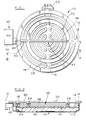
- FIGS 1 and 2 show a radiant electric heater 10 which has a container in the form of a metal dish 12 with an upstanding rim 14 and containing a layer of electrical and thermal insulating material 16.
- This material is for example a microporous insulation which is compressed into the dish 12, and which comprises a highly-dispersed silica powder, such as silica aerogel or pyrogenic (fumed) silica, mixed with a ceramic fibre reinforcement, titanium dioxide opacifier and a small quantity of alumina powder to resist shrinkage.
- a ring-shaped wall 18 of ceramic fibre extends around the inside of the rim 14 of the dish 12, on top of the layer 16 and protruding slightly above the edge of the rim 14.
- the wall 18 When installed in a glass ceramic top cooker the wall 18 is pressed against the underside of a glass ceramic cooking surface 20, shown in Figure 2, the heater being held in position by a spring or other mounting device (not shown). Prior to installation the wall 18 may be retained in position by staples (not shown) extending into the layer 16.
- the layer 16 supports two coiled bare resistance-wire heating elements 22 and 24 arranged concentrically with heating element 24 positioned within and adjacent the wall 18 and heating element 22 positioned within the heating element 24.
- Heating elements 22 and 24 are separated by a ring-shaped wall 26 of ceramic fibre material positioned on top of the layer 16 and retained in position by staples or pins (not shown).
- the height of wall 26 is such that it is not higher, and may be about 1 mm lower, than the wall 18 in order that contact between the wall 18 and the underside of the glass ceramic cooking surface should be maintained and to ensure that no heat is lost from the heater through gaps between the wall 18 and the underside of the glass ceramic cooking surface 20.
- the coiled heating elements 22 and 24 are secured to the layer 16 by, for example, staples held by friction in the insulating material of the layer 16, or by gluing to the layer 16 or to stakes inserted therein.
- the ends of the heating elements 22 and 24 are coupled to respective conductors in an electrical connector block 28 mounted at the edge of the dish 12.
- a temperature control device 40 is provided with an elongate temperature sensor 42 extending across the heater 10 between the heating elements 22 and 24 and the underside of the glass ceramic cooking surface 20 from one edge of the dish, through the wall 18, across the heating element 24, through the wall 26, across the heating element 22 and into the wall 26 again.
- a snap-action switch 44 controlled by the temperature sensor 42 is provided for connection in series with the heating elements 22 and 24, to prevent heating of the cooktop 20 above its maximum safe temperature.
- the temperature control device 40 is shown in more detail in Figure 3 where it can be seen that the temperature sensor comprises a rod 46 of material having a high coefficient of thermal expansion, for example a nickel-chromium or an iron-chromium alloy having a coefficient of thermal expansion of about 16 to 18 x 10 -6 , the rod being arranged coaxially within two axially adjacent tube portions 48, 50 of a tube 52.
- a rod 46 of material having a high coefficient of thermal expansion for example a nickel-chromium or an iron-chromium alloy having a coefficient of thermal expansion of about 16 to 18 x 10 -6 , the rod being arranged coaxially within two axially adjacent tube portions 48, 50 of a tube 52.
- Tube portion 48 which extends over the heating element 22, is made of a material having a low coefficient of thermal expansion, such as fused silica (otherwise sometimes known in the art as quartz glass) having a coefficient of thermal expansion of about 0.5 x 10 -6 , while the tube portion 50, which extends over the heating element 24, is made of an electrically insulating ceramic material having a coefficient of thermal expansion intermediate that of the tube portion 48 and the rod 46.
- a material having a low coefficient of thermal expansion such as fused silica (otherwise sometimes known in the art as quartz glass) having a coefficient of thermal expansion of about 0.5 x 10 -6
- the tube portion 50 which extends over the heating element 24
- the tube portion 50 which extends over the heating element 24
- an electrically insulating ceramic material having a coefficient of thermal expansion intermediate that of the tube portion 48 and the rod 46.
- the tube 52 is provided with end caps 54 and 56, end cap 54 being supported on a mounting plate 58 for the temperature control device.
- the mounting plate 58 is secured to the snap-action switch 44 by means of screws 60.
- the rod 46 passes through apertures in the end cap 54, the mounting plate 58 and the end cap 56 and at the end of the rod adjacent to the end cap 56 the rod is formed with a threaded portion 62.
- An adjusting nut 64 is threaded onto the threaded portion 62 and bears against the end cap 56.
- the other end of the rod 46 is formed with a domed head 64 and a compression spring 66 is positioned between the domed head 64 and a housing 68 of the snap-action switch 44 so as to maintain the rod 46 under tensile stress and to urge the nut 64 against the end cap 56.
- the housing 68 of the snap-action switch 44 is closed in use at its upper side by a cover plate 70 shown in Figures 1 and 2, but for clarity is shown open at its upper side in Figure 3. Any movement of the rod 46 is transferred by way of the domed head 64 to a transfer member 72 which is slidably arranged in a bore formed in the housing 68, the bore being substantially coaxial with the rod 46. One end of the transfer member 72 bears against the domed head 64 and the other end bears against a contact spring 74 of the snap-action switch.
- Contact spring 74 is rigidly secured to a spring carrier 76 which is itself connected to a terminal 78 for conducting electric current. Spring carrier 76 is secured to the housing 68 by a rivet (not shown).
- Contact spring 74 carries a movable switch contact 80 and a snap-action spring 82 which bears against a part of the spring carrier 76 for providing snap-action of the spring 74 and movable contact 80. Also mounted in the housing 68 is a terminal 84 for carrying electric current and a fixed contact 86 connected to the terminal 84.
- the tube portion 50 is made from a ceramic material which has the advantage that it has a naturally high electrical resistivity and thus avoids the need for a separate insulating member around the tube portion. Ceramic materials are also noted for their natural resistance to high temperatures and their long-term stability at such temperatures. Ceramic materials are readily available and can be formed by extrusion and moulding techniques which are relatively inexpensive when compared with the manufacture of a metal tube.
- the coefficient of thermal expansion of the ceramic material may be in the range from 7 to 12.5 x 10 -6 (39 to 78 per cent of the coefficient of thermal expansion of the rod) and preferably in the range from 8.3 to 10.5 x 10 -6 (46 to 66 per cent of the coefficient of thermal conductivity of the rod). Suitable ceramic materials are available under the Trade Marks STEATITE and FREQUENTITE, for example.
- the coefficient of thermal expansion of the ceramic material is not as high as that of the rod, it is possible to adjust the effective expansion performance by regulating the emissivity of the ceramic material.
- Most ceramic materials naturally have a low emissivity; that is they reflect rather than absorb a major proportion of any incident radiation.
- By incorporating a material of high emissivity into the base ceramic material, or by coating the base ceramic material with a material of high emissivity it is possible to raise the emissivity of the resulting ceramic material. This in turn results in absorption of a higher proportion of incident radiation and a higher operating temperature of the increased emissivity ceramic material as compared with the base ceramic material, at least during an initial heating phase.
- the higher operating temperature of the increased emissivity ceramic material offsets at least partly the effect of the lower coefficient of thermal expansion as compared with using a metal tube.
- the temperature control device In use of the temperature control device according to the present invention as incorporated into a radiant electric heater as shown in Figures 1 and 2, when the central heating element 22 is energised the temperature within the wall 26 rises and the glass ceramic cooking surface 20 within the area defined by the wall 26 is also heated. Radiant energy also passes through the glass ceramic surface 20.
- the temperature sensor within the area defined by the wall 26 is influenced by the rising temperature and by the radiant energy and this causes the rod 46 to expand relative to the tube 52. Expansion of the rod 46 causes the domed head 64 to move towards the transfer member 72 and to urge the transfer member towards an actuating point of the contact spring 74.
- the contact spring 74 When the temperature sensor 42 detects a predetermined temperature of, say, 700 °C the contact spring 74 reaches its snap-over point and, assisted by the snap-action spring 82, moves the movable contact 80 to its open position thus de-energising the heating element 22. As the temperature detected by the temperature sensor 42 falls, the rod 46 contracts and permits the contact spring 74 to move back towards its snap-over point. Once the temperature falls sufficiently, the contact spring 74 reaches its snap-over point and, assisted again by the snap-action spring 82, moves the movable contact 80 to its closed position as shown in Figure 3 and energises the heating element 22 once again. This cycle of on-off switching is repeated while the radiant electric heater is energised by a user of the glass ceramic top cooker.
- the radiant electric cooker operates in a similar manner except that the temperature within the annular region between the walls 18 and 26 also rises. This causes the rod 46 in that region to expand and also the ceramic tube portion 50.
- the coefficient of thermal expansion of the ceramic material is a significant proportion of the coefficient of thermal expansion of the rod material, the effect of the heating element 24 on the relative expansion of the rod 46 to the tube 52 is small and the contact spring 74 will reach its snap-over point when that part of the temperature sensor within the area defined by the wall 26 reaches substantially 700 °C and, assisted by the snap-action spring 82, will move the movable contact 80 to its open position thus de-energising both heating elements 22 and 24.
- the contact spring 74 When the temperature within the area defined by the wall 26 falls sufficiently, the contact spring 74 will reach its snap-over point once more and, assisted by the snap-action spring 82, will move the movable contact 80 to its closed position as shown in Figure 3 thus energising both heating elements 22 and 24 once again.
- a temperature control device performs quite adequately.
- a conventional temperature control device is used with a silica tube in place of the ceramic tube we have found that the temperature at which the rod operates the snap-action switch will decrease by about 95 °C when both heating elements are energised compared with when only the inner heating element is energised.
- the temperature decrease is reduced to about 50 °C.
- the temperature control device and the radiant electric heater may be modified in a number of ways from the embodiment shown in the drawings.
- the tube of ceramic material may be interchanged with the tube of fused silica, or more than one of at least one of the tubes may be provided.
- the radiant electric heater may be modified in numerous ways known to the skilled person and illustrated in the prior art.
- one or more of the heating elements may comprise an infrared lamp or more than two heating elements may be provided.
- the heater need not be circular and may take any desired shape, such as rectangular or oval.
Landscapes
- Chemical & Material Sciences (AREA)
- Engineering & Computer Science (AREA)
- Ceramic Engineering (AREA)
- Control Of Temperature (AREA)
- Cookers (AREA)
- Resistance Heating (AREA)
- Electric Stoves And Ranges (AREA)
- Control Of Resistance Heating (AREA)
- Baking, Grill, Roasting (AREA)
- Thermally Actuated Switches (AREA)
Abstract
Description
Claims (9)
- A device for controlling or limiting temperature in an electric cooking appliance, the device comprising switch means (44) and a temperature sensor (42) operatively coupled to the switch means, the temperature sensor comprising a rod (46) arranged substantially coaxially within a tube (52), the rod being made of a material having a first coefficient of thermal expansion and the tube comprising at least two tube portions (48, 50) having different coefficients of thermal expansion such that the overall coefficient of thermal expansion of the tube (52) is less than the coefficient of thermal expansion of the rod (46) with one of the tube portions (48) being made of a material having a second coefficient of thermal expansion lower than the first coefficient of thermal expansion characterised in that another of the tube portions (50) is made from a material having a third coefficient of thermal expansion intermediate the first and second coefficients of thermal expansion, and in that the material having the third coefficient of thermal expansion is made of an electrically insulating ceramic material.
- A device according to claim 1, characterised in that the third coefficient of thermal expansion is from 39 to 78 per cent of the first coefficient of thermal expansion.
- A device according to claim 2, characterised in that the third coefficient of thermal expansion is from 46 to 66 per cent of the first coefficient of thermal expansion.
- A device according to any preceding claim, characterised in that the tube (52) comprises two tube portions (48, 50).
- A device according to any preceding claim, characterised in that the material having a third coefficient of thermal expansion has a relatively high emissivity.
- A device according to claim 5, characterised in that the material having a third coefficient of thermal expansion incorporates, or is coated with, a material having high emissivity.
- A radiant electric heater for a cooking appliance comprising at least two heating elements (22, 24) defining separate heating areas for the cooking appliance, and a device (40) for controlling or limiting temperature according to any preceding claim, the tube portions (48, 50) of the device being dimensioned and positioned such that one or more tube portions (48) of material having the second coefficient of thermal expansion are exposed to heat emitted substantially from one of the heating elements (22) and one or more tube portions (50) of material having the third coefficient of thermal expansion are exposed to heat emitted substantially from the other heating element or elements (24).
- A radiant electric heater according to claim 7, characterised in that the heating elements (22, 24) are separated by one or more walls (26) of thermal insulation material.
- A radiant electric heater according to claim 8, characterised in that one or more junctions between tube portions (48, 50) of material having the second coefficient of thermal expansion and material having the third coefficient of thermal expansion are located within one or more of the separating walls (26).
Applications Claiming Priority (2)
| Application Number | Priority Date | Filing Date | Title |
|---|---|---|---|
| GB9201443 | 1992-01-23 | ||
| GB9201443A GB2263770B (en) | 1992-01-23 | 1992-01-23 | Device for controlling or limiting temperature in an electric cooking appliance |
Publications (3)
| Publication Number | Publication Date |
|---|---|
| EP0552860A2 EP0552860A2 (en) | 1993-07-28 |
| EP0552860A3 EP0552860A3 (en) | 1993-09-22 |
| EP0552860B1 true EP0552860B1 (en) | 1998-03-18 |
Family
ID=10709113
Family Applications (1)
| Application Number | Title | Priority Date | Filing Date |
|---|---|---|---|
| EP93300013A Expired - Lifetime EP0552860B1 (en) | 1992-01-23 | 1993-01-04 | Device for controlling or limiting temperature in an electric cooking appliance |
Country Status (12)
| Country | Link |
|---|---|
| US (1) | US5310993A (en) |
| EP (1) | EP0552860B1 (en) |
| JP (1) | JPH05282976A (en) |
| AT (1) | ATE164284T1 (en) |
| AU (1) | AU651022B2 (en) |
| CA (1) | CA2087891A1 (en) |
| DE (1) | DE69317453T2 (en) |
| DK (1) | DK0552860T3 (en) |
| ES (1) | ES2113482T3 (en) |
| GB (1) | GB2263770B (en) |
| NZ (1) | NZ245734A (en) |
| ZA (1) | ZA9337B (en) |
Families Citing this family (25)
| Publication number | Priority date | Publication date | Assignee | Title |
|---|---|---|---|---|
| US5796075A (en) * | 1992-03-09 | 1998-08-18 | E.G.O. Elektro-Gerate Blanc Und Fisher Gmbh & Co. Kg | Heater, particularly for kitchen appliances |
| DE4438648A1 (en) * | 1994-10-28 | 1996-05-02 | Ego Elektro Blanc & Fischer | Radiant heater |
| JPH09213781A (en) * | 1996-02-01 | 1997-08-15 | Tokyo Electron Ltd | Mounting table structure and processing apparatus using the same |
| IT240975Y1 (en) * | 1996-10-25 | 2001-04-20 | Whirpool Europ S R L | TEMPERATURE AND SAFETY CONTROL DEVICE ASSOCIATED WITH A HEATING ELEMENT OF A GLASS-CERAMIC HOB |
| US5850072A (en) * | 1997-02-18 | 1998-12-15 | Eckert; C. Edward | Electric heater assembly |
| US6049067A (en) * | 1997-02-18 | 2000-04-11 | Eckert; C. Edward | Heated crucible for molten aluminum |
| GB2325533B (en) * | 1997-05-22 | 2001-08-08 | Ceramaspeed Ltd | Method and apparatus for controlling an electric heater |
| DE19846513A1 (en) * | 1998-10-09 | 2000-04-13 | Ego Elektro Geraetebau Gmbh | Switching device for an electrical heating device |
| GB2360591B (en) * | 2000-03-23 | 2004-04-28 | Ceramaspeed Ltd | Temperature sensor |
| ES2231366T3 (en) * | 2000-09-07 | 2005-05-16 | E.G.O. Elektro-Geratebau Gmbh | RADIATION OVEN BELOW A COOKING PLATE, IN PARTICULAR A VITROCERAMIC PLATE. |
| GB2372190B (en) * | 2000-12-16 | 2005-02-09 | Ceramaspeed Ltd | Cooking appliance with radiant electric heater |
| ES2291291T3 (en) * | 2001-01-10 | 2008-03-01 | Electrovac Ag | TEMPERATURE LIMITER. |
| AT409680B (en) * | 2001-04-17 | 2002-10-25 | Electrovac | Temperature |
| US6756569B2 (en) * | 2001-05-11 | 2004-06-29 | Emerson Electric Co. | Temperature sensor for heater unit in cooktop range |
| AT412521B (en) * | 2003-03-10 | 2005-03-25 | Electrovac | PROBE |
| DE102005031069A1 (en) * | 2005-06-24 | 2007-01-11 | E.G.O. Elektro-Gerätebau GmbH | Electromechanical temperature sensing for a cooking appliance and method of making an electromechanical temperature sensing for a cooking appliance |
| DE102005057105A1 (en) * | 2005-11-25 | 2007-05-31 | E.G.O. Elektro-Gerätebau GmbH | Temperature detection device for a heating device and a method for controlling a heating device |
| GB0717051D0 (en) * | 2007-09-01 | 2007-10-17 | Ceramaspeed Ltd | Temperature sensor |
| DE102009038960A1 (en) * | 2009-08-19 | 2011-02-24 | E.G.O. Elektro-Gerätebau GmbH | Temperature sensor and method for adjusting such a temperature sensor |
| JP5416570B2 (en) * | 2009-12-15 | 2014-02-12 | 住友電気工業株式会社 | Heating / cooling device and apparatus equipped with the same |
| US8723085B2 (en) * | 2010-11-24 | 2014-05-13 | Pioneering Technology Corp. | Temperature controlled/limiting heating element for an electric cooking appliance |
| US20130192584A1 (en) * | 2012-01-26 | 2013-08-01 | General Electric Company | Heating element mounting features for a cook top appliance |
| CN103034256B (en) * | 2012-12-17 | 2014-12-10 | 西安交通大学 | Control structure based on water freezing cold expanding principles |
| US10935252B2 (en) | 2015-09-04 | 2021-03-02 | Electrolux Home Products, Inc. | Methods and apparatus for controlling a cooking appliance |
| DE102018213625A1 (en) * | 2018-08-13 | 2020-02-13 | Siemens Aktiengesellschaft | Switchgear temperature measurement |
Family Cites Families (10)
| Publication number | Priority date | Publication date | Assignee | Title |
|---|---|---|---|---|
| US2210526A (en) * | 1937-04-20 | 1940-08-06 | Herbert S Burling | Temperature controlling means |
| US2809523A (en) * | 1953-01-19 | 1957-10-15 | Herbert S Burling | Humidity or temperature differential measuring apparatus |
| US2705746A (en) * | 1953-10-30 | 1955-04-05 | Elsa L Strange | Apparatus for the improvements in thermostats or heat controls |
| DE959140C (en) * | 1955-09-29 | 1957-02-28 | Suerth Zweigniederlassung Der | Bimetal contact thermometer |
| US4008454A (en) * | 1975-11-04 | 1977-02-15 | General Electric Company | Differential expansion rod and tube thermostat |
| DE7826549U1 (en) * | 1978-09-07 | 1978-12-14 | E.G.O. Elektro-Geraete Blanc U. Fischer, 7519 Oberderdingen | TEMPERATURE LIMITER FOR GAS-HEATED CERAMIC GLASS COOKING SURFACES |
| AT376540B (en) * | 1983-01-05 | 1984-11-26 | Electrovac | DEVICE FOR CONTROLLING OR LIMITATION OF AT LEAST ONE TEMPERATURE VALUE OR A TEMPERATURE RANGE OF RADIATION OR CONTACT HEATER FROM ELECTRICAL COOKING EQUIPMENT |
| AT382708B (en) * | 1983-07-07 | 1987-04-10 | Electrovac | DEVICE FOR CONTROLLING OR LIMITATION OF AT LEAST ONE TEMPERATURE VALUE OR A TEMPERATURE RANGE OF RADIATION OR CONTACT HEATER |
| DE3410442A1 (en) * | 1983-09-17 | 1985-09-26 | Ego Elektro Blanc & Fischer | TEMPERATURE PROBE, ESPECIALLY FOR A TEMPERATURE LIMITER FOR A GLASS CERAMIC COOKING UNIT |
| DE3705260A1 (en) * | 1987-02-19 | 1988-09-01 | Ego Elektro Blanc & Fischer | TEMPERATURE LIMITERS |
-
1992
- 1992-01-23 GB GB9201443A patent/GB2263770B/en not_active Expired - Fee Related
-
1993
- 1993-01-04 DK DK93300013T patent/DK0552860T3/en active
- 1993-01-04 EP EP93300013A patent/EP0552860B1/en not_active Expired - Lifetime
- 1993-01-04 AT AT93300013T patent/ATE164284T1/en not_active IP Right Cessation
- 1993-01-04 DE DE69317453T patent/DE69317453T2/en not_active Expired - Fee Related
- 1993-01-04 ES ES93300013T patent/ES2113482T3/en not_active Expired - Lifetime
- 1993-01-05 ZA ZA9337A patent/ZA9337B/en unknown
- 1993-01-05 US US08/000,637 patent/US5310993A/en not_active Expired - Fee Related
- 1993-01-08 AU AU31119/93A patent/AU651022B2/en not_active Ceased
- 1993-01-22 CA CA002087891A patent/CA2087891A1/en not_active Abandoned
- 1993-01-22 JP JP5025981A patent/JPH05282976A/en not_active Withdrawn
- 1993-01-22 NZ NZ245734A patent/NZ245734A/en unknown
Also Published As
| Publication number | Publication date |
|---|---|
| EP0552860A3 (en) | 1993-09-22 |
| DK0552860T3 (en) | 1999-01-11 |
| GB2263770B (en) | 1994-11-02 |
| NZ245734A (en) | 1995-02-24 |
| JPH05282976A (en) | 1993-10-29 |
| ATE164284T1 (en) | 1998-04-15 |
| GB2263770A (en) | 1993-08-04 |
| EP0552860A2 (en) | 1993-07-28 |
| GB9201443D0 (en) | 1992-03-11 |
| DE69317453T2 (en) | 1998-08-13 |
| CA2087891A1 (en) | 1993-07-24 |
| ES2113482T3 (en) | 1998-05-01 |
| US5310993A (en) | 1994-05-10 |
| ZA9337B (en) | 1993-08-05 |
| AU3111993A (en) | 1993-07-29 |
| DE69317453D1 (en) | 1998-04-23 |
| AU651022B2 (en) | 1994-07-07 |
Similar Documents
| Publication | Publication Date | Title |
|---|---|---|
| US5310993A (en) | Device for controlling or limiting temperature in an electric cooking appliance | |
| US4577176A (en) | Temperature regulating device | |
| US4900899A (en) | Cooking unit with radiant heaters | |
| EP0206597B1 (en) | Improvements in or relating to infra-red heaters | |
| JPS6180788A (en) | Radiant heater for cooking apparatus | |
| US4508961A (en) | Electric radiant heater units for glass ceramic top cookers | |
| GB2093320A (en) | An electric cooker | |
| EP0429244B1 (en) | Radiant electric heaters | |
| US6995344B2 (en) | Cooking appliance | |
| EP0560708B1 (en) | Heating and sensing apparatus for range top | |
| EP0943870B1 (en) | Temperature sensing and limiting device | |
| US5113170A (en) | Temperature switch | |
| AU745337B2 (en) | Radiant heating element for a cooking area | |
| GB2069300A (en) | Radiant heating elements for smooth top cookers | |
| EP0777405B1 (en) | Radiant electric heater arrangement and method of operating the same | |
| EP0973356A2 (en) | Radiant electric heater | |
| GB2225920A (en) | Controlling an electric heater unit for an electric ceramic hob | |
| GB2092869A (en) | An electric cooker | |
| GB2116010A (en) | Elastic radiant heater units for use in glass ceramic top cookers | |
| JPH0538555Y2 (en) | ||
| HK1069256A1 (en) | Temperature sensor |
Legal Events
| Date | Code | Title | Description |
|---|---|---|---|
| PUAI | Public reference made under article 153(3) epc to a published international application that has entered the european phase |
Free format text: ORIGINAL CODE: 0009012 |
|
| AK | Designated contracting states |
Kind code of ref document: A2 Designated state(s): AT BE CH DE DK ES FR GB GR IT LI NL PT SE |
|
| PUAL | Search report despatched |
Free format text: ORIGINAL CODE: 0009013 |
|
| AK | Designated contracting states |
Kind code of ref document: A3 Designated state(s): AT BE CH DE DK ES FR GB GR IT LI NL PT SE |
|
| 17P | Request for examination filed |
Effective date: 19931008 |
|
| 17Q | First examination report despatched |
Effective date: 19951221 |
|
| GRAG | Despatch of communication of intention to grant |
Free format text: ORIGINAL CODE: EPIDOS AGRA |
|
| GRAG | Despatch of communication of intention to grant |
Free format text: ORIGINAL CODE: EPIDOS AGRA |
|
| GRAH | Despatch of communication of intention to grant a patent |
Free format text: ORIGINAL CODE: EPIDOS IGRA |
|
| GRAH | Despatch of communication of intention to grant a patent |
Free format text: ORIGINAL CODE: EPIDOS IGRA |
|
| RBV | Designated contracting states (corrected) |
Designated state(s): AT BE CH DE DK ES FR GR IT LI NL PT SE |
|
| GRAA | (expected) grant |
Free format text: ORIGINAL CODE: 0009210 |
|
| AK | Designated contracting states |
Kind code of ref document: B1 Designated state(s): AT BE CH DE DK ES FR GR IT LI NL PT SE |
|
| PG25 | Lapsed in a contracting state [announced via postgrant information from national office to epo] |
Ref country code: GR Free format text: LAPSE BECAUSE OF NON-PAYMENT OF DUE FEES Effective date: 19980318 |
|
| REF | Corresponds to: |
Ref document number: 164284 Country of ref document: AT Date of ref document: 19980415 Kind code of ref document: T |
|
| REG | Reference to a national code |
Ref country code: CH Ref legal event code: EP |
|
| REF | Corresponds to: |
Ref document number: 69317453 Country of ref document: DE Date of ref document: 19980423 |
|
| REG | Reference to a national code |
Ref country code: CH Ref legal event code: NV Representative=s name: ISLER & PEDRAZZINI AG |
|
| REG | Reference to a national code |
Ref country code: ES Ref legal event code: FG2A Ref document number: 2113482 Country of ref document: ES Kind code of ref document: T3 |
|
| ET | Fr: translation filed | ||
| ITF | It: translation for a ep patent filed | ||
| REG | Reference to a national code |
Ref country code: PT Ref legal event code: SC4A Free format text: AVAILABILITY OF NATIONAL TRANSLATION Effective date: 19980526 |
|
| REG | Reference to a national code |
Ref country code: DK Ref legal event code: T3 |
|
| PGFP | Annual fee paid to national office [announced via postgrant information from national office to epo] |
Ref country code: DK Payment date: 19990122 Year of fee payment: 7 |
|
| PLBE | No opposition filed within time limit |
Free format text: ORIGINAL CODE: 0009261 |
|
| 26N | No opposition filed | ||
| PG25 | Lapsed in a contracting state [announced via postgrant information from national office to epo] |
Ref country code: PT Free format text: LAPSE BECAUSE OF NON-PAYMENT OF DUE FEES Effective date: 19990731 |
|
| REG | Reference to a national code |
Ref country code: PT Ref legal event code: MM4A Free format text: LAPSE DUE TO NON-PAYMENT OF FEES Effective date: 19990731 |
|
| PG25 | Lapsed in a contracting state [announced via postgrant information from national office to epo] |
Ref country code: DK Free format text: LAPSE BECAUSE OF NON-PAYMENT OF DUE FEES Effective date: 20000104 |
|
| REG | Reference to a national code |
Ref country code: DK Ref legal event code: EBP |
|
| PGFP | Annual fee paid to national office [announced via postgrant information from national office to epo] |
Ref country code: BE Payment date: 20020117 Year of fee payment: 10 |
|
| PGFP | Annual fee paid to national office [announced via postgrant information from national office to epo] |
Ref country code: FR Payment date: 20020122 Year of fee payment: 10 |
|
| PGFP | Annual fee paid to national office [announced via postgrant information from national office to epo] |
Ref country code: CH Payment date: 20020123 Year of fee payment: 10 |
|
| PGFP | Annual fee paid to national office [announced via postgrant information from national office to epo] |
Ref country code: SE Payment date: 20020128 Year of fee payment: 10 |
|
| PGFP | Annual fee paid to national office [announced via postgrant information from national office to epo] |
Ref country code: NL Payment date: 20020131 Year of fee payment: 10 |
|
| PG25 | Lapsed in a contracting state [announced via postgrant information from national office to epo] |
Ref country code: SE Free format text: LAPSE BECAUSE OF NON-PAYMENT OF DUE FEES Effective date: 20030105 |
|
| PGFP | Annual fee paid to national office [announced via postgrant information from national office to epo] |
Ref country code: AT Payment date: 20030107 Year of fee payment: 11 |
|
| PG25 | Lapsed in a contracting state [announced via postgrant information from national office to epo] |
Ref country code: LI Free format text: LAPSE BECAUSE OF NON-PAYMENT OF DUE FEES Effective date: 20030131 Ref country code: CH Free format text: LAPSE BECAUSE OF NON-PAYMENT OF DUE FEES Effective date: 20030131 Ref country code: BE Free format text: LAPSE BECAUSE OF NON-PAYMENT OF DUE FEES Effective date: 20030131 |
|
| PG25 | Lapsed in a contracting state [announced via postgrant information from national office to epo] |
Ref country code: NL Free format text: LAPSE BECAUSE OF NON-PAYMENT OF DUE FEES Effective date: 20030801 |
|
| EUG | Se: european patent has lapsed | ||
| REG | Reference to a national code |
Ref country code: CH Ref legal event code: PL |
|
| PG25 | Lapsed in a contracting state [announced via postgrant information from national office to epo] |
Ref country code: FR Free format text: LAPSE BECAUSE OF NON-PAYMENT OF DUE FEES Effective date: 20030930 |
|
| NLV4 | Nl: lapsed or anulled due to non-payment of the annual fee |
Effective date: 20030801 |
|
| REG | Reference to a national code |
Ref country code: FR Ref legal event code: ST |
|
| PG25 | Lapsed in a contracting state [announced via postgrant information from national office to epo] |
Ref country code: AT Free format text: LAPSE BECAUSE OF NON-PAYMENT OF DUE FEES Effective date: 20040104 |
|
| PGFP | Annual fee paid to national office [announced via postgrant information from national office to epo] |
Ref country code: ES Payment date: 20041203 Year of fee payment: 13 |
|
| PG25 | Lapsed in a contracting state [announced via postgrant information from national office to epo] |
Ref country code: IT Free format text: LAPSE BECAUSE OF NON-PAYMENT OF DUE FEES;WARNING: LAPSES OF ITALIAN PATENTS WITH EFFECTIVE DATE BEFORE 2007 MAY HAVE OCCURRED AT ANY TIME BEFORE 2007. THE CORRECT EFFECTIVE DATE MAY BE DIFFERENT FROM THE ONE RECORDED. Effective date: 20050104 |
|
| PGFP | Annual fee paid to national office [announced via postgrant information from national office to epo] |
Ref country code: DE Payment date: 20050113 Year of fee payment: 13 |
|
| PG25 | Lapsed in a contracting state [announced via postgrant information from national office to epo] |
Ref country code: ES Free format text: LAPSE BECAUSE OF NON-PAYMENT OF DUE FEES Effective date: 20060105 |
|
| PG25 | Lapsed in a contracting state [announced via postgrant information from national office to epo] |
Ref country code: DE Free format text: LAPSE BECAUSE OF NON-PAYMENT OF DUE FEES Effective date: 20060801 |
|
| REG | Reference to a national code |
Ref country code: ES Ref legal event code: FD2A Effective date: 20060105 |