EP0552840A2 - Dispositif pour transporter et assommer des animaux destinés à l'abattage - Google Patents
Dispositif pour transporter et assommer des animaux destinés à l'abattage Download PDFInfo
- Publication number
- EP0552840A2 EP0552840A2 EP93200127A EP93200127A EP0552840A2 EP 0552840 A2 EP0552840 A2 EP 0552840A2 EP 93200127 A EP93200127 A EP 93200127A EP 93200127 A EP93200127 A EP 93200127A EP 0552840 A2 EP0552840 A2 EP 0552840A2
- Authority
- EP
- European Patent Office
- Prior art keywords
- conveyor
- members
- support body
- animals
- endless element
- Prior art date
- Legal status (The legal status is an assumption and is not a legal conclusion. Google has not performed a legal analysis and makes no representation as to the accuracy of the status listed.)
- Withdrawn
Links
Images


Classifications
-
- A—HUMAN NECESSITIES
- A22—BUTCHERING; MEAT TREATMENT; PROCESSING POULTRY OR FISH
- A22B—SLAUGHTERING
- A22B7/00—Slaughterhouse arrangements
- A22B7/001—Conveying arrangements
-
- A—HUMAN NECESSITIES
- A22—BUTCHERING; MEAT TREATMENT; PROCESSING POULTRY OR FISH
- A22B—SLAUGHTERING
- A22B3/00—Slaughtering or stunning
- A22B3/06—Slaughtering or stunning by electric current
Definitions
- the invention relates to a device for guiding animals, in particular animals for slaughtering such as pigs, sheep and the like, to a treating apparatus, which device is provided with a walkway with a floor and at least one conveyor extending between walkway and treating apparatus and formed by an endless element trained round at least two reversing members, which members are rotatable round lying shafts such that both the carrying and the returning part of the endless element lie in a standing plane.
- Such a device is known for instance from the American patent specification 3991438.
- the animals for slaughter are herein transported between two parallel plates disposed on either side of the conveyor.
- the animals are supported with their belly side on the active part of the conveyor belt and their legs therefore hang freely downward.
- the drawback of the known conveyors is that they have a comparatively hard surface whereby damage can be caused to the animals for slaughtering as a result of muscle contraction during stunning. This impairs the quality of the meat. Internal bleeding has a negative effect on the meat quality.
- the object of the invention is to obviate the above stated drawback and the device according to the invention is distinguished in that the endless element is covered on the side remote from the reversing members with a support body of elastic material softer than the endless element.
- the support body is an elastomer of polyurethane, preferably with a hardness lying in the range of 20-45° shore, preferably 30-40° shore, subject to the type of animal for slaughter that has to be treated.
- the elastic support body can be a closed endless body integrally formed with the endless element.
- the elastic support body can be constructed from mutually spaced blocks carried by the endless element. This furthers a stable position on the conveyor of the animal for treatment.
- two blocks can be arranged mutually adjacent relative to the transporting direction so that the breadth of the conveyor can easily be adapted to the type of animal for slaughtering.
- the elastic support body so broad that it extends on both sides over the endless element and the fixed guiding therefor, so that also in the case of the above mentioned cramp state of the animals for slaughter no contact occurs with the harder parts of the conveyor.
- the invention further relates to a device for treating animals for slaughtering such as pigs, sheep etc., which device is provided with a conveyor belt for the animals for slaughtering in addition to a stunning apparatus containing at least one pair of electrodes, which stunning apparatus is provided with at least one pair of guide members, each of which is arranged to the side of the central longitudinal plane of the conveyor belt such that the mutually facing boundaries of the guide members lie at a predetermined distance to form a boundary space for the head of the animal for slaughter.
- the invention has for its object to obviate the above drawback and provides a device which is distinguished in that the electrode is arranged on the guide member such that the contact part of the electrode is located in front of the boundary space in the transporting direction.
- the electrodes can moreover be provided with a much smaller contact surface of a maximum of 5 cm2 as a result of this favourable placing, wherein these electrodes are preferably ring or pin-shaped.
- the advantage of electrodes with small contact surface is that a better directed current path can be achieved.
- the device is further provided with an electrical feed circuit, wherein the power supply to the guide members amounts to a maximum of 48 volts and that to the electrode at least 200 volts. It is herein recommended to use the applied current between the guide members to energize the drive member of the electrode and to apply the stunning voltage via the electrodes. The electrode will thus be energized immediately and stunning take place when the snout of the animal makes contact with the guide members.
- the conveyor 1 shown in figure 1 consists of an endless element 2 which is trained about three reversing members 3.
- the rotation shafts of the reversing members 3 are horizontal and are disposed in relation to each other such that the carrying part of conveyor 2 extends substantially horizontally, which part runs from a walkway 4 on the left in figure 1 to a treatment apparatus (not shown) located close the right-hand reversing member 3.
- the length of the carrying part is subject to the use thereof.
- the endless element 2 has on the outside, that is on the horizontal active part on the upper side, a support body 5, here in the form of blocks 6. Since the endless element 2 in the embodiment of figures 1-3 is embodied as a link chain consisting of lying links 7 and standing links 8, it is possible to fix each of the blocks 6 on a standing link 8, see also figure 3.
- the support body formed by the blocks 6 is of polyurethane rubber of a determined hardness and dimensions determined by the type of animals for slaughter.
- the width of each block 6 is such that the belly portion of the animal for slaughter is supported in adequate manner such that the legs thereof can hang freely downward on either side of the conveyor.
- Each block 6 is herein supported by a support plate 9 which is welded fixedly onto the standing link, see figure 3.
- Figure 3a shows an alternative embodiment of the upper surface of block 6, which is provided in the middle with a recessed portion 6' for receiving the breast bone.
- the lying links 7 of the chain can be supported by U-shaped profiles 10 on either side of the standing links 8, which can be a permanent component of a frame such that when one of the reversing members 3 is set into drive the lying links 7 slide through the gap-like space formed between the U-shaped profiles 10.
- the plate 9 then slides over the upper surface of the U-shaped profiles and forms a rigid support for the animals for slaughter.
- standing plates 11 Arranged on either side of the fixed U-shaped profiles 10 are standing plates 11 which serve to cover the conveyor such that legs of the animals for slaughter can slide along the outside thereof.
- the above described device operates as follows. By urging on animals for slaughter in the walkway 4 one animal at a time comes to the end thereof and is compelled to drop with the belly onto the support element 6 because the floor of the walkway 4 ends. Once resting with the belly on the support body 5 the animal comes to lie on the blocks 6 with the legs hanging freely on either side of the plates 11 and is further transported in the direction of arrow P1 to a treating apparatus not shown in figure 1. Due to the support body 5 constructed of blocks and manufactured from soft material, neither the belly portion nor the inside of the legs is damaged by the hard elements.
- the walkway 4 can be hung on a tilt point 12 so that when the animal passes the tilting point it automatically sinks downward onto the support body 5 of conveyor 2.
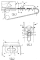
- FIG. 4 shows an alternative embodiment of the conveyor according to the invention.
- the same components are designated here with the same reference numerals.
- an endless element 2 which consists here of a profiled belt 13 that is T-shaped in cross section, see also figure 5.
- the profiled belt is embodied with a connecting plate 14 onto which are arranged two mutually adjacent belts 15 which form the support body according to the invention.
- These endless belts 15 are of relatively soft material of for instance polyurethane with a hardness of between the values of 20-45° shore, preferably 30-40° shore.
- the T-shaped profile 13 is supported between the reversing members 3 by fixed guide plates 11 of a width such that sufficient support of the T-shaped profile 13 is provided and of a material such that the smallest possible coefficient of friction is brought about between T-profile 13 and plates 11.
- Figure 5a shows a further alternative embodiment of the conveyor which consists here of two link chains, guided for instance round reversing wheels as according to figure 1, which link chains lie at a mutual distance.
- Each link chain is again provided with a support plate 9 with block 6 arranged thereon.
- the space a between the blocks again serves to accommodate the breast bone of the animal for treating.
- the stunning apparatus 20 consists here of two plate-like guide members 21 each placed to the side of the central longitudinal plane A-A of the conveyor.
- the mutually facing edges 22 of plates 21 form a boundary of a space 23 which is adapted to the type of animals for slaughtering such that the snout thereof is grasped, oriented and held fast when the animal is moved to the right over conveyor 2, that is, in the direction of arrow P1 in figure 7.
- Each guide plate 21 bears an electrode 24 which is arranged on an arm 25 hingedly connected at 26 to the plate 21.
- a cylinder 27 On the end opposite the hinge 26 is arranged a cylinder 27 which can be actuated by a suitable pressure medium.
- the swivelling movement of arm 25 relative to plate 21 is such that the electrode 24 can be carried from a spread position relative to the central longitudinal plane A-A to the head portion of the animal for slaughter still lying in front of the plates 21 in the transporting direction P1, that is, as closely as possible to the brain portion thereof.
- the electrode 24 can herein be circular or also pin-like in order to keep the contact surface with the head portion as small as possible and the current feed as focussed as possible.
- the stunning apparatus 20 is suspended from a carriage 29 provided with travel wheels 30 which are held in two U-shaped profiles 31 arranged above and along the conveyor 2.
- the carriage has a pivot shaft 32 such that plates 21 can pivot upward round these pivot shafts.
- Such a movable stunning apparatus 20 can be displaced at the speed of the conveyor 2, thus enabling sufficient time for the stunning cycle for the animal for slaughter. After the animal has reached the end of conveyor 2 and vacated it the stunning apparatus 20 can be moved back again to the starting position on the left in figure 7.
- Stunning takes place as follows. As soon as the snout of the animal arrives between the guide edges 22 of plates 21 it can be ascertained by applying a small voltage of for instance 24 volts to the plates 21 that the animal has been detected. This detection current is used to energize cylinder 27, whereby the electrodes 24 are pressed onto either side of the head with a comparatively high pressure force. The electrodes have a relatively low stunning voltage of 300 volts which, because of the pressure force, is nevertheless sufficient to obtain a stunning voltage of for instance 8 amperes. Due to the accurate placing on either side of the head at the location of the brain the other muscles of the animal are hardly affected and damage as a result of tonic cramps will occur hardly or not at all. The danger of back breakage resulting from free movement of the animal on the conveyor 2 is hereby also prevented.
- Both the guide members can for example be integrated to a single ring which is for instance suspended for upward folding on the carriage.
Landscapes
- Life Sciences & Earth Sciences (AREA)
- Engineering & Computer Science (AREA)
- Food Science & Technology (AREA)
- Processing Of Meat And Fish (AREA)
- Catching Or Destruction (AREA)
Applications Claiming Priority (2)
| Application Number | Priority Date | Filing Date | Title |
|---|---|---|---|
| NL9200104 | 1992-01-20 | ||
| NL9200104A NL9200104A (nl) | 1992-01-20 | 1992-01-20 | Transport- en verdovingsinrichting voor slachtvee. |
Publications (2)
| Publication Number | Publication Date |
|---|---|
| EP0552840A2 true EP0552840A2 (fr) | 1993-07-28 |
| EP0552840A3 EP0552840A3 (en) | 1993-12-29 |
Family
ID=19860328
Family Applications (1)
| Application Number | Title | Priority Date | Filing Date |
|---|---|---|---|
| EP19930200127 Withdrawn EP0552840A3 (en) | 1992-01-20 | 1993-01-19 | Transporting and stunning device for animals for slaughter |
Country Status (2)
| Country | Link |
|---|---|
| EP (1) | EP0552840A3 (fr) |
| NL (1) | NL9200104A (fr) |
Cited By (1)
| Publication number | Priority date | Publication date | Assignee | Title |
|---|---|---|---|---|
| CN102986808A (zh) * | 2012-10-19 | 2013-03-27 | 南京凯宏肉类机械有限公司 | 一种活挂托胸式输送麻电机 |
Citations (5)
| Publication number | Priority date | Publication date | Assignee | Title |
|---|---|---|---|---|
| US1370663A (en) * | 1918-09-09 | 1921-03-08 | Goodrich Co B F | Carrier-cushion for sandpapering-machines |
| US2954113A (en) * | 1957-01-09 | 1960-09-27 | Chain Belt Co | Conveyer chain attachments |
| US3991438A (en) * | 1975-10-01 | 1976-11-16 | Council of Livestock Protection, Inc. | Double-rail conveyor design |
| US4171738A (en) * | 1977-08-19 | 1979-10-23 | Glopak Industries Limited | Conveyor mechanism for conveying flexible pouches adapted to contain fluids, granular substances and the like |
| GB2211808A (en) * | 1987-10-30 | 1989-07-12 | Js Engineering | Chain conveyor |
-
1992
- 1992-01-20 NL NL9200104A patent/NL9200104A/nl unknown
-
1993
- 1993-01-19 EP EP19930200127 patent/EP0552840A3/en not_active Withdrawn
Patent Citations (5)
| Publication number | Priority date | Publication date | Assignee | Title |
|---|---|---|---|---|
| US1370663A (en) * | 1918-09-09 | 1921-03-08 | Goodrich Co B F | Carrier-cushion for sandpapering-machines |
| US2954113A (en) * | 1957-01-09 | 1960-09-27 | Chain Belt Co | Conveyer chain attachments |
| US3991438A (en) * | 1975-10-01 | 1976-11-16 | Council of Livestock Protection, Inc. | Double-rail conveyor design |
| US4171738A (en) * | 1977-08-19 | 1979-10-23 | Glopak Industries Limited | Conveyor mechanism for conveying flexible pouches adapted to contain fluids, granular substances and the like |
| GB2211808A (en) * | 1987-10-30 | 1989-07-12 | Js Engineering | Chain conveyor |
Cited By (1)
| Publication number | Priority date | Publication date | Assignee | Title |
|---|---|---|---|---|
| CN102986808A (zh) * | 2012-10-19 | 2013-03-27 | 南京凯宏肉类机械有限公司 | 一种活挂托胸式输送麻电机 |
Also Published As
| Publication number | Publication date |
|---|---|
| EP0552840A3 (en) | 1993-12-29 |
| NL9200104A (nl) | 1993-08-16 |
Similar Documents
| Publication | Publication Date | Title |
|---|---|---|
| US6338673B2 (en) | Electrical animal stun/kill apparatus | |
| US5888132A (en) | Post kill tenderization of poultry meat through constant electrical stimulation | |
| DE60030534D1 (de) | Verfahren und vorrichtung zum bearbeiten von geschlachteten tieren | |
| ATE122849T1 (de) | Einstellbares system zum filettieren von geflügelbrust. | |
| EP0584142B1 (fr) | Systeme a bande transporteuse servant a accrocher la volaille | |
| US4221021A (en) | Method and apparatus for electrical stimulation of an animal carcass | |
| EP1175151B1 (fr) | Procede de traitement de carcasses d'animaux et appareil d'application d'une stimulation electrique | |
| US4468837A (en) | Apparatus for automatically stunning animals to be slaughtered | |
| DE3067336D1 (en) | An apparatus for electrically stunning animals to be slaughtered, in particular pigs | |
| FR2390903A1 (fr) | Dispositif pour assommer ou abattre electriquement des animaux de boucherie notamment des porcs | |
| EP0552840A2 (fr) | Dispositif pour transporter et assommer des animaux destinés à l'abattage | |
| SU1079164A3 (ru) | Устройство дл электрического оглушени животных | |
| US3051984A (en) | Apparatus for restraining animals | |
| ATE63422T1 (de) | Vorrichtung zum filetieren. | |
| US3115670A (en) | Method for restraining animals | |
| DE59204093D1 (de) | Vorrichtung zum Zuführen und Wenden von mit Geschirrteilen beladenen Tabletts. | |
| US5906540A (en) | Animal stunning system prior to slaughter | |
| NZ214315A (en) | Electrical stunning apparatus and method | |
| ATE10422T1 (de) | Apparat zum elektrischen betaeuben von schlachtvieh. | |
| GB2417408A (en) | Device for electrically slaughtering fish | |
| CA2946452A1 (fr) | Procede et appareil de disposition d'oiseau dans une position afin d'etre suspendu a un etrier | |
| US3143762A (en) | Process for facilitating the immobilization and slaughtering of animals | |
| US3991438A (en) | Double-rail conveyor design | |
| DE59000618D1 (de) | Vorrichtung zum wegtransportieren von entnommenen inneren schlachttierorganen. | |
| EP0060004A1 (fr) | Installation d'assommage pour animaux de boucherie |
Legal Events
| Date | Code | Title | Description |
|---|---|---|---|
| PUAI | Public reference made under article 153(3) epc to a published international application that has entered the european phase |
Free format text: ORIGINAL CODE: 0009012 |
|
| AK | Designated contracting states |
Kind code of ref document: A2 Designated state(s): AT BE CH DE DK ES FR GB IE IT LI NL PT SE |
|
| PUAL | Search report despatched |
Free format text: ORIGINAL CODE: 0009013 |
|
| AK | Designated contracting states |
Kind code of ref document: A3 Designated state(s): AT BE CH DE DK ES FR GB IE IT LI NL PT SE |
|
| STAA | Information on the status of an ep patent application or granted ep patent |
Free format text: STATUS: THE APPLICATION IS DEEMED TO BE WITHDRAWN |
|
| 18D | Application deemed to be withdrawn |
Effective date: 19940630 |