EP0552794B1 - Efficient and reliable large-amount data transmission method and system - Google Patents
Efficient and reliable large-amount data transmission method and system Download PDFInfo
- Publication number
- EP0552794B1 EP0552794B1 EP93100955A EP93100955A EP0552794B1 EP 0552794 B1 EP0552794 B1 EP 0552794B1 EP 93100955 A EP93100955 A EP 93100955A EP 93100955 A EP93100955 A EP 93100955A EP 0552794 B1 EP0552794 B1 EP 0552794B1
- Authority
- EP
- European Patent Office
- Prior art keywords
- data
- transmission
- reception
- terminal
- information
- Prior art date
- Legal status (The legal status is an assumption and is not a legal conclusion. Google has not performed a legal analysis and makes no representation as to the accuracy of the status listed.)
- Expired - Lifetime
Links
- 230000005540 biological transmission Effects 0.000 title claims description 115
- 238000000034 method Methods 0.000 title claims description 39
- 238000012545 processing Methods 0.000 claims description 66
- 238000004891 communication Methods 0.000 claims description 41
- 230000004044 response Effects 0.000 claims description 13
- 238000001514 detection method Methods 0.000 claims description 7
- 230000007812 deficiency Effects 0.000 claims 8
- 230000003213 activating effect Effects 0.000 claims 2
- 238000010586 diagram Methods 0.000 description 10
- 238000012546 transfer Methods 0.000 description 6
- 230000006870 function Effects 0.000 description 4
- 230000002159 abnormal effect Effects 0.000 description 3
- 230000005856 abnormality Effects 0.000 description 3
- 230000003993 interaction Effects 0.000 description 2
- 238000005259 measurement Methods 0.000 description 2
- 230000002411 adverse Effects 0.000 description 1
- 238000012790 confirmation Methods 0.000 description 1
- 230000000694 effects Effects 0.000 description 1
- 230000012447 hatching Effects 0.000 description 1
- 230000010365 information processing Effects 0.000 description 1
- 238000009434 installation Methods 0.000 description 1
- 238000004519 manufacturing process Methods 0.000 description 1
- 239000013307 optical fiber Substances 0.000 description 1
- 230000011664 signaling Effects 0.000 description 1
Images





Classifications
-
- H—ELECTRICITY
- H04—ELECTRIC COMMUNICATION TECHNIQUE
- H04Q—SELECTING
- H04Q11/00—Selecting arrangements for multiplex systems
- H04Q11/04—Selecting arrangements for multiplex systems for time-division multiplexing
- H04Q11/0428—Integrated services digital network, i.e. systems for transmission of different types of digitised signals, e.g. speech, data, telecentral, television signals
- H04Q11/0478—Provisions for broadband connections
-
- H—ELECTRICITY
- H04—ELECTRIC COMMUNICATION TECHNIQUE
- H04L—TRANSMISSION OF DIGITAL INFORMATION, e.g. TELEGRAPHIC COMMUNICATION
- H04L12/00—Data switching networks
- H04L12/54—Store-and-forward switching systems
- H04L12/56—Packet switching systems
- H04L12/5601—Transfer mode dependent, e.g. ATM
- H04L2012/5629—Admission control
- H04L2012/563—Signalling, e.g. protocols, reference model
-
- H—ELECTRICITY
- H04—ELECTRIC COMMUNICATION TECHNIQUE
- H04L—TRANSMISSION OF DIGITAL INFORMATION, e.g. TELEGRAPHIC COMMUNICATION
- H04L12/00—Data switching networks
- H04L12/54—Store-and-forward switching systems
- H04L12/56—Packet switching systems
- H04L12/5601—Transfer mode dependent, e.g. ATM
- H04L2012/5638—Services, e.g. multimedia, GOS, QOS
- H04L2012/5645—Connectionless
Definitions
- US-A-5,021,949 discloses a data transmission method and system with the features included in the first part of each of claims 1 and 13.
- the document teaches enabling date communication or interoperability from conventional IBM host computers that will permit SNA installations communicate over IP packet switched networks, such as defence data networks, between hosts or between a host and a remote terminal.
- a channel attached front end processor which includes an SNA interface and an interface to a packet switched network is provided between a host and an SNA network.
- the front end processor operates to imbed the SNA protocol information in an IP datagram or to extract such information from the IP datagram.
- a point-to-point circuit or channel is made (established) for a plurality of receiver terminals (corresponding to the terminals B, C and C denoted by 203, 204 and 205, respectively).
- TCP/IP Transmission Control Protocol/Internet Protocol
- RFC793 and RFC791 respectively.
- RFC is an abbreviation of "Request for Comments” and represents a document number in "DDN Protocol Handbook" published by the SRI International DDN Network Information Center.
- the protocol referred to as the TCP/IP is known as a transmission control procedure which can provide a one-to-one communication with a high reliability by making available a communication error check function, a retransmission function upon occurrence of transmission error such as drop-out, falsification and others.
- it is required to establish a virtual communication path (or virtual connection) between the sender terminal and the receiver terminal in precedence to effectuating the TCP/IP communication.
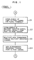
- the point-to-point channel or circuit is made for a plurality of nodes or terminals, it is intended to mean that virtual connection is established between the terminal A and the terminals B, C and D in the case of the network shown in Fig. 2.
- a retransmission processing is executed by utilizing the point-to-point channel of a high reliability which has been established in the step 101. However, unless any retransmission request is issued, this step 104 is spared. Fig.
- FIG. 3B is a diagram illustrating schematically the concept or mode of the transmission performed by utilizing the point-to-point channel.
- a phantom line 303 extending from the sender terminal A to the receiver terminal D indicates that no information retransmitting is performed for the terminal D although the connection has been established between these terminals A and D.
- the sender terminal A first transmits the information frame to the receiver terminal B and then to the receiver terminal C on a one-to-one basis.
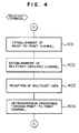
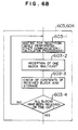
- a step 403 the information frames transmitted through the multicast channel established in the step 103 are received.
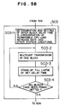
- step 503 may include steps 503-1 to 503-4 shown in Fig. 5B.
- step 503-4 decision is made after laps of the preset delay time as to whether or not all the information blocks of the predetermined number have been transmitted. When any block remains to be sent, the step 503-2 is resumed.
- a step 508 the point-to-point channel and the multicast channel made in the step 501 are broken or removed.
- a step 602 an answer is returned in response to the pre-transmission acknowledgement inquiry issued in the step 502 mentioned previously.
- the sender terminal can confirm that the receiver terminals are sound.
- the receiver terminal may make the multicast channel at the time point when it receives the pre-transmission acknowledgement inquiry.
- the probability of overflow of the communication hardware buffer can be suppressed lower than a predetermined allowable value while the influence of overhead of the CPU can be mitigated to such a level that the CPU load rate capable of evading error in fetching the received data by the application program is maintained.
- conflict in the communication can positively be prevented, as a result of which the reliability of the other periodical communications performed without acknowledgement can be maintained, as it is, while excluding extraneous processing overhead involved otherwise by the retransmission processing for the large amount of data.
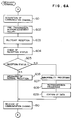
- a step 606 is executed for messaging the normal reception to the sender terminal.
- a step 609 the data block is edited by using the block ID information received in the step 608.
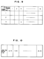
- the data of the third block is received and stored in the memory area identified by "3/15".
- a step 1202 the pre-transmission acknowledgement inquiry issued in the step 1102 by the sender terminal is received.
- Processing steps 1204 to 1211 shown in Fig. 12 correspond to the processing steps 604 to 610 described hereinbefore by reference to Fig. 6A.
- the pre-transmission acknowledgement inquiry sent from the sender terminal to the receiver terminal in the step 1202 and received by the latter in the step 1301 shown in Fig. 13 may be performed without resorting to the simple broadcast transmission. More specifically, the pre-transmission acknowledgement inquiry issued in the step 1301 may be added with a data content identifying code. In that case, in the step 1202, the receiver terminal checks the content identifying code as to whether it coincides with an identification code stored previously in the receiver terminal. Only when the coincidence is detected, the receiver terminal receives the pre-transmission acknowledgement inquiry in a selective manner, so to say.
- the communication network 202 is constituted by a LAN system in which an optical fiber cable having a transmission rate, for example, of 100 M-bit rate is employed.
Landscapes
- Engineering & Computer Science (AREA)
- Computer Networks & Wireless Communication (AREA)
- Communication Control (AREA)
- Data Exchanges In Wide-Area Networks (AREA)
- Small-Scale Networks (AREA)
Description
Claims (27)
- A data transmission method for transferring a large amount of data among a plurality of computer terminals (201, 203, 204, 205; A, B, C, D) through a network (202) serving as a data transmission line to which said plurality of computer terminals (A, B, C, D) are connected, whereina plurality of information frames is sent from a sender terminal (A) to a receiver terminal (B, C, D) successively in accordance with a connectionless transmission protocol (102);
characterized by:receiving from said receiver terminal by said sender terminal a reception acknowledging information frame or alternatively a retransmission request information frame in accordance with a connection-oriented transmission protocol which ensures high reliability, and sending from said sender terminal to said receiver terminal a frame of data to be retransmitted in response to said retransmission request information frame, if issued, in accordance with said connection-oriented transmission protocol of high reliability (104). - The method of claim 1, wherein sending of said plurality of information frames is performed in the form of a one-to-N broadcast transmission in which said information frames are transmitted from one sender terminal (A) to N receiver terminals (B, C, D), wherein N represents an integer greater than two.
- The method of claim 2, wherein the reception of said reception acknowledging information frame or alternatively said retransmission request information frame is realised by activating said N destination receiver terminals (B, C, D) from the sender terminal side.
- The method of claim 2, wherein said sender terminal affixes an identification code for identifying the content of said data to said information frame; further comprising the steps of:affixing to said information frame an identification code for identifying the content of said information frame; andreceiving selectively said information frames by said receiver terminals by discriminatively identifying the codes affixed to said transmission information frames.
- The method of claim 1, wherein in precedence to transmission of said plurality of information frames, said sender terminal (A) sends reception ready inquiry data to said receiver terminal (B, C, D) and receives acknowledgement data from said receiver terminal.
- The method of claim 1, further comprising the steps of:sending from said sender terminal to said receiver terminal through a broadcast transmission reception ready inquiry data affixed with an identification code identifying the content of said information frame in precedence to transmission of said plurality of information frames;identifying discriminatively said code at the receiver terminal; andsending acknowledgement data to said sender terminal from the receiver terminal which received selectively said reception ready inquiry data in accordance with the connection-oriented protocol ensuring high reliability.
- The method of claim 1, wherein said connection-less transmission protocol is a user datagram protocol/internet protocol UDP/IP, and said connection-oriented transmission protocol ensuring high reliability is a transmission control protocol/internet protocol TCP/IP.
- The method of claim 1, wherein each of said information frames is divided into blocks and a delay time is interposed between said blocks upon transmission thereof for controlling data flow, said delay time being so determined that increase in a CPU load in each of said terminals is suppressed or no conflict takes place between said transmission of a large amount of data and other communication performed between said terminals.
- The method of claim 8, wherein said delay time is set on the basis of a permissible load increase rate of the CPU and overhead of the CPU per unit transmission rate in said receiver terminal or said sender terminal and the number of blocks resulting from division of one information frame.
- The method of claim 8, further comprising the steps of:detecting a rate of increase in the load of the CPU of said receiver terminal brought about by the transmission of a large amount of data;messaging said sender terminal of excess in the CPU load in response to an indication that the detected CPU load increase rate is higher than a preset permissible CPU load increase rate in said receiver terminal; andincreasing said delay time in response to reception of said message.
- The method of claim 8, wherein said delay time is so set in said receiver terminal or sender terminal that no overflow takes place in a sending/receiving buffer which partakes in the connectionless communication.
- The method of claim 8, further comprising the steps of:detecting reception deficiency of data transmitted through other connectionless communication than that for transmitting a large amount of data, said reception deficiency being brought about due to a buffer overflow in the receiver terminal;messaging said data reception deficiency to said sender terminal;and increasing said delay time in response to said message of data reception deficiency.
- A data transmission system for transferring a large amount of data among a plurality of computer terminals (201, 203, 204, 205) through a network (202) serving as a data transmission line to which said plurality of computer terminals are connected, comprisingfirst transmission means for sending from a sender terminal to a receiver terminal a plurality of information frames successively in accordance with a connectionless transmission protocol;
characterized byreception means for receiving from said receiver terminal a reception acknowledging information frame or alternatively a retransmission request information frame in accordance with a connection-oriented transmission protocol which ensures high reliability; andsecond transmission means for sending to said receiver terminal a frame of data to be retransmitted in response to said retransmission request information frame, if issued, in accordance with said connection-oriented transmission protocol of high reliability. - The system of claim 13, wherein the first transmission means is arranged such that sending of said plurality of information frames is performed in the form of a one-to-N broadcast transmission in which said information frames are transmitted from one sender terminal to N receiver terminals, wherein N represents an integer greater than two inclusive thereof.
- The system of claim 14, wherein said reception means for receiving said reception acknowledging information frame or alternatively said retransmission request information frame includes means for activating said N destination receiver terminals from the sender terminal side.
- The system of claim 14, wherein said sender terminal affixes an identification code for identifying the content of said data to said information frame; further comprising:means for affixing to said information frame an identification code for identifying the content of said information frame; andbroadcast reception means for receiving selectively said information frames by discriminatively identifying the codes affixed to said transmission information frames in said receiver terminals.
- The system of claim 13, wherein said sender terminal includes means for sending reception ready inquiry data to said receiver terminal in precedence to transmission of said plurality of information frames and receiving acknowledging data from said receiver terminal.
- The system of claim 13, further comprising:first transmission means for sending through a broadcast transmission to said receiver terminal from said sender terminal reception ready inquiry data affixed with identification codes identifying the contents of said information frames in precedence to transmission of said plurality of information frames;identifying means for identifying discriminatively said codes at the receiver terminals; andsecond transmission means for sending reception ready acknowledging data to said sender terminal from the receiver terminal which received selectively said reception ready inquiry data in accordance with the connection-oriented protocol ensuring high reliability.
- The system of claim 13, wherein said connectionless transmission protocol is a user datagram protocol/internet protocol UDP/IP, and said connection-oriented transmission protocol ensuring high reliability is a transmission control protocol/internet protocol TCP/IP.
- The system of claim 13, wherein each of said information frames is divided into blocks and a delay time is interposed between said blocks upon transmission thereof for controlling data flow, further comprising:first means for detecting rate of increase in a CPU load in each of said terminals;second means for detecting conflict possibly occurring between said large amount data of transmission and other communications in each of said terminals; andmeans for setting said delay time in dependence on at least one of outputs from said first and second means.
- The system of claim 20: comprising means for setting said delay time on the basis of a permissible load increase rate of the CPU and overhead of the CPU per unit transmission rate in said receiver terminal or said sender terminal and the number of blocks resulting from the division of one information frame.
- The system of claim 20, further comprising:means for detecting a rate of increase in the load of the CPU of said receiver terminal brought about by the large amount of data transmission;means for messaging said sender terminal of an excess in the CPU load in response to an indication that the detected CPU load increase rate is higher than a preset permissible CPU load increase rate in said receiver terminal; andmeans for increasing said delay time in response to reception of said message.
- The system of claim 20, wherein said delay time is so set in said receiver terminal or sender terminal that no overflow takes place in a sending/ receiving buffer which partakes in the connectionless communication.
- The system of claim 20, further comprising:means for detecting reception deficiency of data transmitted through other connectionless communication than that for transmitting a large amount of data, said reception deficiency being brought about due to a buffer overflow in the receiver terminal;means for messaging said data reception deficiency to said sender terminal; andmeans for increasing said delay time in response to said message of data reception deficiency.
- An object processing control system, comprising a plurality of stations (203, 204, 205) each including a programmed object controller equipped with a computer, a data communication network (202) to which said plurality of stations are connected, and a broadcasting station (201) equipped with a computer for broadcasting a processing data file to said plurality of controllers through said network,each of said stations including:detecting means for detecting actual processing status of the object undergoing a processing and transmitting periodically the detected data to the controller of the associated station; andmeans for processing said object based on data and/or commands from said controller;said broadcasting station including:means for dividing said processing data file into a plurality of successive information blocks;means for setting a delay time between said successive information blocks, said delay time being determined on the basis of a load increase rate of the computer of each station and/or an interval at which said detection data is periodically transmitted to said controller;means for transmitting said information blocks and said detection data on a connectionless transmission service basis, and transmitting a retransmission information frame on an connection-oriented transmission service basis; andmeans for receiving a reception acknowledging information frame for acknowledging the reception of said information blocks on an connection-oriented transmission service basis.
- A traffic control system, comprising a plurality of control nodes (B, C, D) located in transportation paths each including a programmed route controller equipped with a computer, a data communication network (202) to which said plurality of control nodes are connected, and a broadcasting node (A) equipped with a computer for broadcasting a vehicle operation data file to said plurality of controllers through said network, each of said control nodes including:a plurality of sensor means for detecting actual vehicle operation status between the control nodes to generate data indicative of the status and transmitting periodically the generated data to the controller of the associated nodes; andcontrol means for controlling the vehicle operation in accordance with data and/or commands from said controller;said broadcasting node including:means for dividing said vehicle operation data file into a plurality of successive information blocks;means for setting a delay time between said successive information blocks, said delay time being determined on the basis of a load increase rate of the computer of each control node and/or an interval at which said detection data is periodically transmitted to said controller;means for transmitting said information blocks and said detection data on a connectionless transmission service basis, and transmitting a retransmission information frame on a connection-oriented transmission service basis; andmeans for receiving a reception acknowledging information frame for acknowledging the reception of said information blocks on a connection-oriented transmission service basis.
- The system of claim 26, wherein said broadcasting node is constituted by a particular one of said plurality of control nodes.
Applications Claiming Priority (3)
| Application Number | Priority Date | Filing Date | Title |
|---|---|---|---|
| JP10764/92 | 1992-01-24 | ||
| JP1076492 | 1992-01-24 | ||
| JP4010764A JPH05207023A (en) | 1992-01-24 | 1992-01-24 | Mass data transmission method |
Publications (3)
| Publication Number | Publication Date |
|---|---|
| EP0552794A2 EP0552794A2 (en) | 1993-07-28 |
| EP0552794A3 EP0552794A3 (en) | 1995-05-24 |
| EP0552794B1 true EP0552794B1 (en) | 2000-05-10 |
Family
ID=11759399
Family Applications (1)
| Application Number | Title | Priority Date | Filing Date |
|---|---|---|---|
| EP93100955A Expired - Lifetime EP0552794B1 (en) | 1992-01-24 | 1993-01-22 | Efficient and reliable large-amount data transmission method and system |
Country Status (4)
| Country | Link |
|---|---|
| US (1) | US5572678A (en) |
| EP (1) | EP0552794B1 (en) |
| JP (1) | JPH05207023A (en) |
| DE (1) | DE69328578T2 (en) |
Families Citing this family (86)
| Publication number | Priority date | Publication date | Assignee | Title |
|---|---|---|---|---|
| US5819110A (en) | 1995-06-05 | 1998-10-06 | Ricoh Company, Ltd. | System for determining whether connection or connectionless modes of communication should be used to transmit information between devices in accordance with priorities of events |
| US20020004812A1 (en) * | 1997-06-26 | 2002-01-10 | Tetsuro Motoyama | Method and system for diagnosis and control of machines using connectionless modes having delivery monitoring and an alternate communication mode |
| US5603081A (en) * | 1993-11-01 | 1997-02-11 | Telefonaktiebolaget Lm Ericsson | Method for communicating in a wireless communication system |
| FR2702113B1 (en) * | 1993-02-26 | 1995-04-28 | Alcatel Business Systems | Asynchronous switching network for communication installation core. |
| JPH0856221A (en) * | 1994-08-10 | 1996-02-27 | Nec Corp | Multiple address communication system |
| WO1996017462A2 (en) | 1994-11-21 | 1996-06-06 | Oracle Corporation | A reliable connectionless network protocol |
| US6453438B1 (en) | 1995-01-19 | 2002-09-17 | The Fantastic Corporation | System and method for automatically rescheduling a data transmission to members of a group |
| US5553083B1 (en) * | 1995-01-19 | 2000-05-16 | Starburst Comm Corp | Method for quickly and reliably transmitting frames of data over communications links |
| US6625652B1 (en) | 1995-01-19 | 2003-09-23 | The Fantastic Corporation | System and method for host list pruning |
| US6873627B1 (en) | 1995-01-19 | 2005-03-29 | The Fantastic Corporation | System and method for sending packets over a computer network |
| US5793973A (en) * | 1995-07-14 | 1998-08-11 | Microsoft Corporation | Method and system for opportunistic broadcasting of data |
| JP4160642B2 (en) * | 1995-09-08 | 2008-10-01 | 株式会社日立製作所 | Network data transfer method |
| US6470391B2 (en) * | 1995-09-08 | 2002-10-22 | Hitachi, Ltd. | Method for transmitting data via a network in a form of divided sub-packets |
| JP3515839B2 (en) * | 1995-10-11 | 2004-04-05 | 富士通株式会社 | Communication system between computer systems |
| JP3097525B2 (en) * | 1995-11-10 | 2000-10-10 | 株式会社日立製作所 | Data transmission method for performing information filtering |
| US6108304A (en) * | 1996-03-08 | 2000-08-22 | Abe; Hajime | Packet switching network, packet switching equipment, and network management equipment |
| US5732213A (en) * | 1996-03-22 | 1998-03-24 | Ericsson Inc. | System and method of testing open systems interconnection (OSI) layers in telecommunication networks |
| US5862329A (en) * | 1996-04-18 | 1999-01-19 | International Business Machines Corporation | Method system and article of manufacture for multi-casting audio visual material |
| US6298386B1 (en) * | 1996-08-14 | 2001-10-02 | Emc Corporation | Network file server having a message collector queue for connection and connectionless oriented protocols |
| US6046999A (en) * | 1996-09-03 | 2000-04-04 | Hitachi, Ltd. | Router apparatus using ATM switch |
| JP3605242B2 (en) * | 1996-11-12 | 2004-12-22 | 富士通株式会社 | Data transmission device, data reception device, and data file storage medium |
| US5832232A (en) * | 1996-12-16 | 1998-11-03 | Intel Corporation | Method and apparatus for providing user-based flow control in a network system |
| US5948060A (en) * | 1997-01-24 | 1999-09-07 | International Business Machines Corporation | Speeding-up communication rates on links transferring data structures by a method of handing scatter/gather of storage blocks in commanded computer systems |
| US5958053A (en) * | 1997-01-30 | 1999-09-28 | At&T Corp. | Communications protocol with improved security |
| US6067567A (en) * | 1997-02-20 | 2000-05-23 | International Business Machines Corporation | Message distribution capability which uses distribution nodes to collect acknowledgements for a primary node |
| JP3579208B2 (en) * | 1997-03-11 | 2004-10-20 | 株式会社東芝 | Node device and message exchange method |
| JP3390824B2 (en) * | 1997-03-19 | 2003-03-31 | 株式会社日立製作所 | Multiplexing control device and fault recovery method therefor |
| EP0876023A1 (en) * | 1997-04-30 | 1998-11-04 | Sony Corporation | Transmitter and transmitting method, receiver and receiving method, and transceiver and transmitting/receiving method |
| US6304911B1 (en) * | 1997-06-25 | 2001-10-16 | Advanced Micro Devices, Inc. | Information packet reception indicator for reducing the utilization of a host system processor unit |
| US6014710A (en) * | 1997-06-30 | 2000-01-11 | Sun Microsystems, Inc. | System and method for message transmission between network nodes using remote wires |
| GB9716964D0 (en) * | 1997-08-09 | 1997-10-15 | Aquatic Innovations Ltd | Vehicle seat |
| US6385647B1 (en) * | 1997-08-18 | 2002-05-07 | Mci Communications Corporations | System for selectively routing data via either a network that supports Internet protocol or via satellite transmission network based on size of the data |
| US6226301B1 (en) * | 1998-02-19 | 2001-05-01 | Nokia Mobile Phones Ltd | Method and apparatus for segmentation and assembly of data frames for retransmission in a telecommunications system |
| US6728771B2 (en) * | 1998-03-20 | 2004-04-27 | Siemens Information And Communication Networks, Inc. | Generic transport option for transporting messages in relay or broadcast mode via combinations of ISDN B-channels or D-channels |
| US6405257B1 (en) * | 1998-06-26 | 2002-06-11 | Verizon Laboratories Inc. | Method and system for burst congestion control in an internet protocol network |
| GB2339368A (en) * | 1998-07-08 | 2000-01-19 | Ibm | Data communications protocol with efficient packing of datagrams |
| US6515994B1 (en) * | 1998-07-30 | 2003-02-04 | Lucent Technologies Inc. | Method of communication in a communications network and apparatus therefor |
| US6289012B1 (en) | 1998-08-03 | 2001-09-11 | Instanton Corporation | High concurrency data download apparatus and method |
| US7013305B2 (en) | 2001-10-01 | 2006-03-14 | International Business Machines Corporation | Managing the state of coupling facility structures, detecting by one or more systems coupled to the coupling facility, the suspended state of the duplexed command, detecting being independent of message exchange |
| JP3250532B2 (en) * | 1998-11-24 | 2002-01-28 | 日本電気株式会社 | Data transmitting / receiving system, data receiving apparatus, and data receiving method |
| US6389550B1 (en) * | 1998-12-23 | 2002-05-14 | Ncr Corporation | High availability protocol computing and method |
| US7197504B1 (en) | 1999-04-23 | 2007-03-27 | Oracle International Corporation | System and method for generating decision trees |
| US6850987B1 (en) * | 1999-06-01 | 2005-02-01 | Fastforward Networks, Inc. | System for multipoint infrastructure transport in a computer network |
| CA2376214A1 (en) * | 1999-06-08 | 2000-12-14 | The Trustees Of Columbia University In The City Of New York | Network telephony appliance and system for inter/intranet telephony |
| AU5879800A (en) * | 1999-06-18 | 2001-01-09 | Trustees Of Columbia University In The City Of New York, The | System and method for receiving over a network a broadcast from a broadcast source |
| JP2001016233A (en) * | 1999-06-28 | 2001-01-19 | Oki Electric Ind Co Ltd | Data communication method |
| KR20010028832A (en) * | 1999-09-27 | 2001-04-06 | 최항석 | System for provoding services based on connection-oriented protocol in the web service based on connection-less protocol |
| US6912586B1 (en) * | 1999-11-12 | 2005-06-28 | International Business Machines Corporation | Apparatus for journaling during software deployment and method therefor |
| US6674994B1 (en) | 1999-12-01 | 2004-01-06 | Panamsat Corporation | Pickup and delivery of data files |
| US6564064B1 (en) * | 1999-12-01 | 2003-05-13 | Trimble Navigation Limited | Cellular telephone using pseudolites for determining location |
| US6615274B1 (en) | 1999-12-09 | 2003-09-02 | International Business Machines Corporation | Computer network control systems and methods |
| US6704782B1 (en) | 1999-12-09 | 2004-03-09 | International Business Machines Corporation | System and methods for real time progress monitoring in a computer network |
| US6588011B1 (en) | 1999-12-14 | 2003-07-01 | International Business Machines Corporation | Apparatus for automatically generating restore process during software depolyment and method therefor |
| US6604237B1 (en) | 1999-12-14 | 2003-08-05 | International Business Machines Corporation | Apparatus for journaling during software deployment and method therefor |
| US7191208B1 (en) | 1999-12-14 | 2007-03-13 | International Business Machines Corporation | Methods of selectively distributing data in a computer network and systems using the same |
| US6629285B1 (en) * | 2000-01-04 | 2003-09-30 | Nokia Corporation | Data transmission |
| US6799218B1 (en) * | 2000-04-07 | 2004-09-28 | Motorola, Inc. | Device and method for managing communications between data communications systems |
| US6910063B1 (en) * | 2000-06-28 | 2005-06-21 | Microsoft Corporation | System and method of enhancing web server throughput in single and multiple processor systems |
| CA2416959C (en) | 2000-08-11 | 2009-08-04 | The Trustees Of Columbia University In The City Of New York | System and method for unified messaging in inter/intranet telephony |
| US7254605B1 (en) | 2000-10-26 | 2007-08-07 | Austen Services Llc | Method of modulating the transmission frequency in a real time opinion research network |
| US6907002B2 (en) * | 2000-12-29 | 2005-06-14 | Nortel Networks Limited | Burst switching in a high capacity network |
| US7184401B2 (en) * | 2001-02-05 | 2007-02-27 | Interdigital Technology Corporation | Link-aware transmission control protocol |
| US7606930B1 (en) * | 2001-02-20 | 2009-10-20 | At&T Intellectual Property Ii, L.P. | Enhanced channel access mechanisms for an HPNA network |
| US7099935B2 (en) * | 2001-10-01 | 2006-08-29 | International Business Machines Corporation | Dynamically determining whether to process requests synchronously or asynchronously |
| CA2464508A1 (en) * | 2001-11-30 | 2003-06-12 | Rory Stewart Turnbull | Method and apparatus for critical time multimedia data transmission |
| JP3821034B2 (en) * | 2002-03-22 | 2006-09-13 | ブラザー工業株式会社 | Network management system, managed device, management device, program |
| JP3920675B2 (en) * | 2002-03-22 | 2007-05-30 | 株式会社リコー | Data communication method, computer, program, and storage medium |
| JP2003333075A (en) * | 2002-05-16 | 2003-11-21 | Web-Base Co Ltd | Data transmission / reception system |
| JP2004038575A (en) * | 2002-07-03 | 2004-02-05 | Sony Corp | Data transmitting / receiving system and data transmitting / receiving method, information providing apparatus and information providing method, and data receiving apparatus and data receiving method |
| US7327731B1 (en) | 2003-04-09 | 2008-02-05 | At&T Corp. | Point-to-multipoint connections for data delivery |
| US9420072B2 (en) | 2003-04-25 | 2016-08-16 | Z124 | Smartphone databoost |
| US7889689B2 (en) * | 2003-08-26 | 2011-02-15 | Nokia Corporation | Supporting a switch between channels for a multicast transmission |
| US7376150B2 (en) * | 2004-07-30 | 2008-05-20 | Nokia Corporation | Point-to-point repair response mechanism for point-to-multipoint transmission systems |
| US7596653B2 (en) * | 2004-11-08 | 2009-09-29 | Intel Corporation | Technique for broadcasting messages on a point-to-point interconnect |
| WO2007055399A1 (en) | 2005-11-10 | 2007-05-18 | Matsushita Electric Industrial Co., Ltd. | Method and apparatus for power line communication |
| JP4749840B2 (en) * | 2005-11-10 | 2011-08-17 | パナソニック株式会社 | Communication apparatus and communication method |
| CA2577030A1 (en) * | 2007-01-31 | 2008-07-31 | Unlimi-Tech Software Inc. | Improved data transfer method, system and protocol |
| JP5623143B2 (en) | 2010-06-04 | 2014-11-12 | 京セラ株式会社 | Wireless terminal apparatus and control method |
| US8751682B2 (en) * | 2010-09-27 | 2014-06-10 | Z124 | Data transfer using high speed connection, high integrity connection, and descriptor |
| US8788576B2 (en) | 2010-09-27 | 2014-07-22 | Z124 | High speed parallel data exchange with receiver side data handling |
| US8499051B2 (en) | 2011-07-21 | 2013-07-30 | Z124 | Multiple messaging communication optimization |
| US9351237B2 (en) | 2011-09-27 | 2016-05-24 | Z124 | Displaying of charging status on dual screen device |
| US9774721B2 (en) | 2011-09-27 | 2017-09-26 | Z124 | LTE upgrade module |
| JP5216922B1 (en) * | 2012-01-06 | 2013-06-19 | Flens株式会社 | Learning support server, learning support system, and learning support program |
| WO2014049738A1 (en) * | 2012-09-26 | 2014-04-03 | 株式会社 日立製作所 | Large-scale specifications transmission system, large-scale specifications transmission method, and server |
| US11418965B2 (en) | 2020-05-04 | 2022-08-16 | T-Mobile Usa, Inc. | Hybrid mesh of licensed and unlicensed wireless frequency bands |
Family Cites Families (24)
| Publication number | Priority date | Publication date | Assignee | Title |
|---|---|---|---|---|
| JPS5947905B2 (en) * | 1980-02-08 | 1984-11-22 | 株式会社日立製作所 | Information transmission method using a common transmission path |
| US4535448A (en) * | 1982-12-10 | 1985-08-13 | At&T Bell Laboratories | Dual bus communication system |
| US4536877A (en) * | 1983-01-21 | 1985-08-20 | E-Systems, Inc. | Tack-on acknowledgment in computer networks |
| JPH0648811B2 (en) * | 1986-04-04 | 1994-06-22 | 株式会社日立製作所 | Complex network data communication system |
| US4803681A (en) * | 1986-07-08 | 1989-02-07 | Nec Corporation | Data transmission control system |
| FR2616024B1 (en) * | 1987-05-26 | 1989-07-21 | Quinquis Jean Paul | SYSTEM AND METHOD FOR PACKET FLOW CONTROL |
| US5021949A (en) * | 1988-02-29 | 1991-06-04 | International Business Machines Corporation | Method and apparatus for linking an SNA host to a remote SNA host over a packet switched communications network |
| US5377327A (en) * | 1988-04-22 | 1994-12-27 | Digital Equipment Corporation | Congestion avoidance scheme for computer networks |
| US5091849A (en) * | 1988-10-24 | 1992-02-25 | The Walt Disney Company | Computer image production system utilizing first and second networks for separately transferring control information and digital image data |
| US5050162A (en) * | 1989-03-20 | 1991-09-17 | Bell Communications Research, Inc. | Congestion free packet network |
| US5025457A (en) * | 1989-04-21 | 1991-06-18 | Codex Corporation | Synchronizing continuous bit stream oriented terminals in a communications network |
| GB8911395D0 (en) * | 1989-05-18 | 1989-07-05 | British Telecomm | Data communications network |
| GB8916489D0 (en) * | 1989-07-19 | 1989-09-06 | British Telecomm | Data communication method and system |
| US5231631A (en) * | 1989-08-15 | 1993-07-27 | At&T Bell Laboratories | Arrangement for regulating traffic in a high speed data network |
| US5193151A (en) * | 1989-08-30 | 1993-03-09 | Digital Equipment Corporation | Delay-based congestion avoidance in computer networks |
| US5191583A (en) * | 1989-11-03 | 1993-03-02 | Microcom Systems, Inc. | Method and apparatus for effecting efficient transmission of data |
| US5243595A (en) * | 1990-01-30 | 1993-09-07 | Johnson Service Company | Combined connectionless and connection-oriented network control system |
| US5224095A (en) * | 1990-01-30 | 1993-06-29 | Johnson Service Company | Network control system and method |
| WO1991015069A1 (en) * | 1990-03-29 | 1991-10-03 | Sf2 Corporation | Method and apparatus for scheduling access to a csma communication medium |
| JP2904298B2 (en) * | 1990-03-30 | 1999-06-14 | マツダ株式会社 | Multiplex transmission equipment for vehicles |
| US5197127A (en) * | 1990-09-24 | 1993-03-23 | International Business Machines Corporation | Expert system method for performing window protocol-based data flow analysis within a data communication network |
| US5208810A (en) * | 1990-10-10 | 1993-05-04 | Seiko Corp. | Method of data flow control |
| DE69130853T2 (en) * | 1990-11-21 | 1999-07-22 | At & T Corp., New York, N.Y. | Bandwidth management and congestion protection for access to broadband ISDN networks |
| US5179556A (en) * | 1991-08-02 | 1993-01-12 | Washington University | Bandwidth management and congestion control scheme for multicast ATM networks |
-
1992
- 1992-01-24 JP JP4010764A patent/JPH05207023A/en active Pending
-
1993
- 1993-01-22 EP EP93100955A patent/EP0552794B1/en not_active Expired - Lifetime
- 1993-01-22 DE DE69328578T patent/DE69328578T2/en not_active Expired - Lifetime
- 1993-01-25 US US08/008,303 patent/US5572678A/en not_active Expired - Lifetime
Also Published As
| Publication number | Publication date |
|---|---|
| JPH05207023A (en) | 1993-08-13 |
| US5572678A (en) | 1996-11-05 |
| DE69328578D1 (en) | 2000-06-15 |
| EP0552794A2 (en) | 1993-07-28 |
| EP0552794A3 (en) | 1995-05-24 |
| DE69328578T2 (en) | 2001-02-01 |
Similar Documents
| Publication | Publication Date | Title |
|---|---|---|
| US5572678A (en) | System for sending frames from sender to receiver using connectionless protocol and receiving acknowledging frame and retransmission request frame from receiver using connection oriented protocol | |
| EP0303830B1 (en) | Multicast data distribution system | |
| AU644800B2 (en) | Data communication method and system | |
| US6282669B1 (en) | Ethernet communication redundancy method | |
| EP0507579B1 (en) | Multiplexed transmission between nodes with cyclic redundancy check calculation | |
| GB2452991A (en) | Acknowledging receipt of data to both a relay node and a sending node | |
| JP2806466B2 (en) | Data transmission control method | |
| US6570852B1 (en) | Relay communication system | |
| US20060095518A1 (en) | Software application for modular sensor network node | |
| JPH09214545A (en) | Network communication control method | |
| JPS5933953A (en) | Communication control system in communication network system | |
| JP3313563B2 (en) | Data transmission control method | |
| JPH0832531A (en) | Broadcast communication method | |
| US7260114B1 (en) | System and method for tracking multilink packet information | |
| JPH05130141A (en) | Packet transmitter | |
| JPH11234347A (en) | Buffer management method and system in data communication | |
| JPS61214829A (en) | Inter-system communication control system | |
| JPH06112972A (en) | Packet re-transmission system | |
| JP2002232434A (en) | Radio lan system and slave station used for the same | |
| JP2008042562A (en) | Gateway device | |
| CN120916202A (en) | Narrow-band virtual broadband system based on multi-terminal collaboration and implementation method | |
| JPH0381852A (en) | Connection control system | |
| CN117544617A (en) | Data message breakpoint continuous transmission method and device | |
| JPS60190050A (en) | Transmission method | |
| JPS59210751A (en) | Node failure recovering system of network |
Legal Events
| Date | Code | Title | Description |
|---|---|---|---|
| PUAI | Public reference made under article 153(3) epc to a published international application that has entered the european phase |
Free format text: ORIGINAL CODE: 0009012 |
|
| AK | Designated contracting states |
Kind code of ref document: A2 Designated state(s): DE FR GB |
|
| PUAL | Search report despatched |
Free format text: ORIGINAL CODE: 0009013 |
|
| AK | Designated contracting states |
Kind code of ref document: A3 Designated state(s): DE FR GB |
|
| 17P | Request for examination filed |
Effective date: 19951109 |
|
| 17Q | First examination report despatched |
Effective date: 19980609 |
|
| GRAG | Despatch of communication of intention to grant |
Free format text: ORIGINAL CODE: EPIDOS AGRA |
|
| RIC1 | Information provided on ipc code assigned before grant |
Free format text: 6H 04Q 11/04 A |
|
| GRAG | Despatch of communication of intention to grant |
Free format text: ORIGINAL CODE: EPIDOS AGRA |
|
| GRAG | Despatch of communication of intention to grant |
Free format text: ORIGINAL CODE: EPIDOS AGRA |
|
| GRAH | Despatch of communication of intention to grant a patent |
Free format text: ORIGINAL CODE: EPIDOS IGRA |
|
| GRAH | Despatch of communication of intention to grant a patent |
Free format text: ORIGINAL CODE: EPIDOS IGRA |
|
| GRAA | (expected) grant |
Free format text: ORIGINAL CODE: 0009210 |
|
| AK | Designated contracting states |
Kind code of ref document: B1 Designated state(s): DE FR GB |
|
| REF | Corresponds to: |
Ref document number: 69328578 Country of ref document: DE Date of ref document: 20000615 |
|
| ET | Fr: translation filed | ||
| K2C3 | Correction of patent specification (complete document) published |
Effective date: 20000510 |
|
| PLBE | No opposition filed within time limit |
Free format text: ORIGINAL CODE: 0009261 |
|
| STAA | Information on the status of an ep patent application or granted ep patent |
Free format text: STATUS: NO OPPOSITION FILED WITHIN TIME LIMIT |
|
| 26N | No opposition filed | ||
| REG | Reference to a national code |
Ref country code: GB Ref legal event code: IF02 |
|
| PGFP | Annual fee paid to national office [announced via postgrant information from national office to epo] |
Ref country code: FR Payment date: 20120202 Year of fee payment: 20 |
|
| PGFP | Annual fee paid to national office [announced via postgrant information from national office to epo] |
Ref country code: DE Payment date: 20120118 Year of fee payment: 20 |
|
| PGFP | Annual fee paid to national office [announced via postgrant information from national office to epo] |
Ref country code: GB Payment date: 20120118 Year of fee payment: 20 |
|
| REG | Reference to a national code |
Ref country code: DE Ref legal event code: R071 Ref document number: 69328578 Country of ref document: DE |
|
| REG | Reference to a national code |
Ref country code: DE Ref legal event code: R071 Ref document number: 69328578 Country of ref document: DE |
|
| REG | Reference to a national code |
Ref country code: GB Ref legal event code: PE20 Expiry date: 20130121 |
|
| PG25 | Lapsed in a contracting state [announced via postgrant information from national office to epo] |
Ref country code: DE Free format text: LAPSE BECAUSE OF EXPIRATION OF PROTECTION Effective date: 20130123 Ref country code: GB Free format text: LAPSE BECAUSE OF EXPIRATION OF PROTECTION Effective date: 20130121 |