EP0551786A1 - Verfahren zum Installieren eines Kabels mit Durchquerung von Hindernissen ausgehend von einem auf einer Trommel aufgewickelten Kabel grosser Länge - Google Patents
Verfahren zum Installieren eines Kabels mit Durchquerung von Hindernissen ausgehend von einem auf einer Trommel aufgewickelten Kabel grosser Länge Download PDFInfo
- Publication number
- EP0551786A1 EP0551786A1 EP92403595A EP92403595A EP0551786A1 EP 0551786 A1 EP0551786 A1 EP 0551786A1 EP 92403595 A EP92403595 A EP 92403595A EP 92403595 A EP92403595 A EP 92403595A EP 0551786 A1 EP0551786 A1 EP 0551786A1
- Authority
- EP
- European Patent Office
- Prior art keywords
- reel
- cable
- drum
- auxiliary
- obstacle
- Prior art date
- Legal status (The legal status is an assumption and is not a legal conclusion. Google has not performed a legal analysis and makes no representation as to the accuracy of the status listed.)
- Withdrawn
Links
Images


Classifications
-
- B—PERFORMING OPERATIONS; TRANSPORTING
- B65—CONVEYING; PACKING; STORING; HANDLING THIN OR FILAMENTARY MATERIAL
- B65H—HANDLING THIN OR FILAMENTARY MATERIAL, e.g. SHEETS, WEBS, CABLES
- B65H57/00—Guides for filamentary materials; Supports therefor
- B65H57/18—Guides for filamentary materials; Supports therefor mounted to facilitate unwinding of material from packages
- B65H57/20—Flyers
-
- B—PERFORMING OPERATIONS; TRANSPORTING
- B65—CONVEYING; PACKING; STORING; HANDLING THIN OR FILAMENTARY MATERIAL
- B65H—HANDLING THIN OR FILAMENTARY MATERIAL, e.g. SHEETS, WEBS, CABLES
- B65H54/00—Winding, coiling, or depositing filamentary material
-
- B—PERFORMING OPERATIONS; TRANSPORTING
- B65—CONVEYING; PACKING; STORING; HANDLING THIN OR FILAMENTARY MATERIAL
- B65H—HANDLING THIN OR FILAMENTARY MATERIAL, e.g. SHEETS, WEBS, CABLES
- B65H54/00—Winding, coiling, or depositing filamentary material
- B65H54/02—Winding and traversing material on to reels, bobbins, tubes, or like package cores or formers
- B65H54/28—Traversing devices; Package-shaping arrangements
- B65H54/2896—Flyers
-
- B—PERFORMING OPERATIONS; TRANSPORTING
- B65—CONVEYING; PACKING; STORING; HANDLING THIN OR FILAMENTARY MATERIAL
- B65H—HANDLING THIN OR FILAMENTARY MATERIAL, e.g. SHEETS, WEBS, CABLES
- B65H75/00—Storing webs, tapes, or filamentary material, e.g. on reels
- B65H75/02—Cores, formers, supports, or holders for coiled, wound, or folded material, e.g. reels, spindles, bobbins, cop tubes, cans, mandrels or chucks
- B65H75/34—Cores, formers, supports, or holders for coiled, wound, or folded material, e.g. reels, spindles, bobbins, cop tubes, cans, mandrels or chucks specially adapted or mounted for storing and repeatedly paying-out and re-storing lengths of material provided for particular purposes, e.g. anchored hoses, power cables
-
- H—ELECTRICITY
- H02—GENERATION; CONVERSION OR DISTRIBUTION OF ELECTRIC POWER
- H02G—INSTALLATION OF ELECTRIC CABLES OR LINES, OR OF COMBINED OPTICAL AND ELECTRIC CABLES OR LINES
- H02G1/00—Methods or apparatus specially adapted for installing, maintaining, repairing or dismantling electric cables or lines
- H02G1/06—Methods or apparatus specially adapted for installing, maintaining, repairing or dismantling electric cables or lines for laying cables, e.g. laying apparatus on vehicle
- H02G1/08—Methods or apparatus specially adapted for installing, maintaining, repairing or dismantling electric cables or lines for laying cables, e.g. laying apparatus on vehicle through tubing or conduit, e.g. rod or draw wire for pushing or pulling
-
- H—ELECTRICITY
- H02—GENERATION; CONVERSION OR DISTRIBUTION OF ELECTRIC POWER
- H02G—INSTALLATION OF ELECTRIC CABLES OR LINES, OR OF COMBINED OPTICAL AND ELECTRIC CABLES OR LINES
- H02G11/00—Arrangements of electric cables or lines between relatively-movable parts
- H02G11/02—Arrangements of electric cables or lines between relatively-movable parts using take-up reel or drum
Definitions
- the present invention relates to a method and a device for installing a cable with crossing of obstacles from a very long cable wound on a reel.
- a first widely used method in particular for telephone cables, consists in burying contiguous tubes, that is to say in placing the tubes end to end, the ends of which open into manholes in the open air. Then the cable is introduced into a tube and it is advanced by pulling or pushing it, for example with compressed air. This method requires two successive operations and obliges to build the cable so that it resists the pulls resulting from the friction forces appearing during the pulling.
- a second method consists in digging a deep and narrow trench and during the same operation to bury the cable which is then not subjected to any traction. This process encounters a major difficulty when crossing the road. Indeed, it must cut the road which requires traffic stop. It is also possible to drill a hole under the road and introduce a protective tube into it, then pass the cable through the tube. In this case, you must fully unwind the cable from the reel that carries it, roll it in eight on the ground and pass it through the tube, then take it up on a reel on the other side of this obstacle to continue laying. However, these cable manipulations are dangerous for the cable and must be carried out manually by the operators.
- the present invention aims to remedy the drawbacks of known solutions and proposes to create a method for laying cables of great length with crossing obstacles such as roads, railways, and ... by drilling in the obstacle without having to open this obstacle by a bleeding.
- the invention also proposes to create a device allowing the implementation of this method.
- the invention relates to the installation of any filiform element or similar to a cable and which is conditioned on drums or coils such as electrical or optical cables, tubes for fluids, bars, etc.
- this method eliminates any direct manual intervention on the cable in addition to taking the end of the cable and its introduction into the passage through the obstacle. This process makes it possible to eliminate the extremely delicate and dangerous operation of removing the cable from the drum following a free arrangement, in a figure of eight, upstream of the obstacle then taking up this cable at the obstacle output on a drum. The method also avoids any trenching in the obstacle.
- main drum / auxiliary drum must be taken in the general sense; they are only used to simplify the description of the process since the main reel can play the role of auxiliary reel or the auxiliary reel that of main reel following several passages in series through obstacles, the cable passing from one reel to the other alternately.
- the cable is wound on the auxiliary reel or on the main reel by performing a cutting movement.
- the present invention also relates to a device for implementing the method both in its general expression and in its particular applications, either a single drum, or a partitioned drum.
- the synchronous drive means is an electric axis.
- the rewinding crew comprises a cutting means.
- the crews comprise a guide means for receiving the cable along the axis of rotation of each crew and guiding the cable to the exit and to the respective entry of the crew.
- the auxiliary reel is carried by a spindle secured to a movable console in translation of controlled cutting and the main reel is rotatably mounted on an axis aligned with the auxiliary reel, this axis carrying the transfer assembly and is connected to a rotational drive means, means cooperating with the main reel to exert a winding torque.
- the transfer equipment for the auxiliary reel is mounted on a tube aligned with the axis of rotation of the equipment and intended to be crossed by the cable leaving the equipment, this tube being mounted in a roller bearing and is connected to a rotational drive means, this tube comprising a removable part to allow the extraction of the cable without cutting it.
- the rewinding unit associated with the main drum at the outlet of obstacles is mounted integrally in rotation on a sleeve driven in rotation by a drive means and mounted in a roller bearing, this sleeve being traversed by the cable upstream of the equipment itself and this sleeve comprises a removable peripheral part to allow the extraction of the cable at the end of rewinding, the main reel being mounted on an axis mounted free in rotation in a support cooperating with translation means, this support comprising a rotation drive means connected to the reel by means of an electromagnetic brake.
- the tube and sleeve have removable parts.
- the transfer assembly is carried by a grooved shaft housed in a grooved sleeve itself driven in rotation by a drive means, this sleeve passing freely through a console fixed and receiving externally, in free rotation, the auxiliary reel, the splined shaft being controlled in axial translation to effect a cutting movement
- the transfer crew comprises a radial arm carrying near the axis a pulley and at its end a pulley as well as a transverse arm provided at its ends with a pulley, this equipment ensuring with these pulleys the transfer of the cable from the main reel to the auxiliary reel and by these pulleys the unwinding of the cable from the auxiliary reel.
- the receiving equipment consists of a radial arm carrying a pulley near the axis and an end pulley as well as a transverse arm carrying a pulley, this equipment being fixed to a splined shaft connected to an arm controlled in translation parallel to the axis of the shaft for controlling the crew in cutting motion, as well as a splined cylinder receiving the splined shaft, this cylinder carrying a pulley cooperating with a means drive, and the main reel is mounted for free rotation on the grooved cylinder by being connected to an electromagnetic coupling device, one part is integral with the main reel and the other is connected to a drive means to induce a winding torque in the reel.
- the method consists in installing a cable 1 by crossing an obstacle 2 in which a passage 3 has been made with an inlet 4 and an outlet 5.
- This obstacle is for example a roadway which must be crossed not by a trench which partially destroys the structure, requires restoration work and above all impedes the use of the traffic lane for a significant time but underground.
- the crossing of the obstacle 2 is done through a drilled passage 3 having an inlet 4 and an outlet 5.
- the cable 1 of great length is presented wound on a reel 6 (first reel), carried in a non-rotatable manner by the axis 7 of a support 8 itself embarked on a vehicle or placed on the ground.
- the device comprises, at the level of the first drum 6, a reeling unit 9 formed of a radial arm 10 carrying a transverse arm 11 one end of which is provided with a pulley 12 and the other with a pulley 13.
- This equipment also includes a deflection member such as a pulley 14 located substantially in the axis XX of the passage 3.
- a deflection member such as a pulley 15 belonging to a rewinding unit 16 formed of a radial arm 17 carrying a cross member 18 and the ends of which are provided with pulleys 19, 20.
- the cable passes over the deflection members or pulleys 15, 19, 20 as indicated by arrows to come onto the barrel 21 of a second reel 22.
- This second reel 22 undergoes a rewinding torque exerted by a drive member 23 (motor or brake torque) inducing in the cable a certain tension to ensure its correct rewinding .
- the reel 9 or rewind 16 crews rotate in synchronism and in the same direction (arrows A, B).
- the member 23 exerting the winding torque allows the second reel 22 to compensate for the difference in diameter between the unwound ply of the first reel 6 and the rewound ply on the second reel 21.
- Synchronization and cutting are ensured by a control circuit 100 acting on the motors 101, 102 controlling the crews 9, 16 and the motor 23. Synchronization is thus carried out along an "electrical axis".
- the pulley or deflection member 14 is arranged so that at the outlet, the cable is aligned with the passage 3, that is to say on the axis XX. It is the same on the output side 5 for the receiving pulley 15.
- this implicitly supposes that the crews 9 and 16 also rotate around this axis XX. This corresponds to the simplest case of implementing the method of the invention.
- Unfortunately such a situation only rarely exists in practice because the obstacle to be crossed is often a road and there is not enough on either side of the road that the axis of the crews 9 and 16 can be placed as low as the passage 3. Usually, this axis is located higher as indicated in Figure 2.
- the return member 14 is constituted by a set of pulleys or rollers or a static deflection member 15 ′ in the form of a guide ring crossed by the cable at the outlet from the reel member 9 and advantageously supplemented for example by a guide pulley 24 at the inlet 4 and a guide pulley 25 at exit 5 of passage 3.
- the output reception means are not shown. They also include a guide member having the same function as the member 15 'described above on the inlet side.
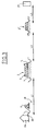
- FIG. 3 schematically shows an example of a site in which a cable must be installed with the passage of obstacles such as roadways, underground, without making a trench but passing through a horizontal or inclined borehole.
- the cable can be an electric cable or a transmission cable in the usual sense of the term but also an optical cable or even a tube possibly receiving an internal element, for example a sheath used for the installation of an optical cable or bars and, in general, the invention relates to the installation of a very long element wound on a reel and which requires the passage of obstacles through a tube, drilling or other and not a trench.
- This cable 1 is initially wound on a main reel 6 itself carried by a vehicle shown diagrammatically.
- the end 28 of the cable is connected during a first step to the first connection point 26.
- the cable 1 is placed in a trench 29, for example over the length L1, until you meet obstacle 2 to cross.
- This obstacle 2 is for example a railway track or a road. This obstacle cannot also be crossed in a trench, does one pierce it with a drilled passage 3, for example horizontal or substantially horizontal, in which the cable must be passed between the entry point 4 and the point of exit 5.
- the installation methods on the unwinding are: laying in gutters and laying in the open ground by trencher or by vibrating coulter (the vibrating coulter does not open a trench).
- the method according to the invention allows the cable 1 to pass through these various obstacles 2, 2 ′ without having to unwind the cable in order to roll it up into eight at the entrance to each obstacle.
- FIG. 4 shows the first reel or main reel 6 loaded with the cable 1 at the outlet of the trench 29.
- a second empty drum or auxiliary drum 22 is put in place, and a rotary transfer unit 30, the assembly preferably being placed aligned with the axis YY of the main drum 6.
- the auxiliary reel 22 is placed on a support so that it is accessible over its entire periphery but it is blocked in rotation. This is shown schematically by link 31. However, the crew of transfer 30 and the main reel 6 remain free to rotate about the axis YY.
- the transfer assembly 30 consists of a radial arm 32 carrying a transverse arm 33 provided at each of its ends with a pulley 34, 35. This assembly 30 can rotate around the axis YY.
- the main reel 6 performs a rotational movement in the direction of the arrow F by opposing a certain opposing torque to ensure the tension of the cable when it is transferred to the auxiliary reel 22.
- this loop is in a way the part of the cable 1 included between the exit of the trench 29 and its winding on the main reel 6) like the main reel 6 can rotate freely (subject to the opposing torque mentioned above) it is possible to manually pull a cable loop 1A sufficient to place the cable on the drum 36 of the drum 22 and on the pulleys 34, 35 of the crew 30.
- the transfer unit 30 is rotated in the direction of arrow C, that is to say in the direction of clockwise for an observer 37.
- the reel 22 remains fixed.
- the cable 1 runs in the direction of arrow E and is wound on the drum 36 of the drum 22 while unwinding from the main drum 6.
- the latter is in a way pulled in rotation in the direction of the arrow C by the crew 30 and the opposing torque which it opposes is used to create the winding tension.
- the main reel 6, empty, is then removed from its location ( Figure 7) to be transported to the other side of the obstacle 2 (side of the exit 5).
- a length of cable 1 of the reel 22 is unwound, either manually or with the unwinding crew 30 (the cable now circulating in the opposite direction (arrow F) and the crew 30 also turning in the opposite direction to the previous rotational movement (arrow G) to thread the cable in the passage 3 from the inlet 4 to the outlet 5. Then one collects the cable to put it on the receiving crew 16 of structure similar to that of the transfer or unwinding crew, that is to say comprising two pulleys 39, 40 carried by a cross member 41 itself carried by a radial arm 42, the whole turning around the axis ZZ on which the reel 6 is also mounted.
- the end 38 of the cable is fixed to the barrel 43 of the drum 6 passing from behind according to FIG. 8 (always for the observer 37) (it should be noted that the winding on the drum 22 and on the drum 43 of the main drum 6 are done according to rotations in opposite directions ).
- the cable is guided at the inlet 4 of the passage 3 (straight) by the inlet pulley 14 and at the outlet 5 by the pulley 15 so as to be aligned in the axis of the passage 3.
- FIG. 9 shows an embodiment of the assembly shown schematically in FIG. 5.
- the auxiliary drum 22 is carried by a pin 44 secured to a movable console 45 in translation in the direction of the double arrow I on a rail 46, the console 45 having a thread 47 receiving a mother screw 48 driven in rotation controlled by a motor 49 (preferably a geared motor).
- a motor 49 preferably a geared motor
- the transfer unit 30 is mobile in rotation and static in translation along the axis of the double arrow I.
- the main reel 6 is mounted for rotation by means of bearings 50 on the axis 51 which is itself rotary and one end of which carries the branch 32 of the transfer equipment 30.
- the other end of the axis 51 is provided with a drive crown 52 cooperating with a crown 53 carried by the output shaft of a motor 54 (or geared motor).
- This axis 51 is rotatably mounted in the bearing 55.
- the opposing torque or braking torque is applied to the main reel 6 by means, for example of an electromagnetic brake constituted by a fixed cage 56 and a part 57 cooperating with the cage 56 and which is integral in rotation with the drum 6 or with the rotary part carrying the drum 6 on the axis 51.
- FIG. 10 shows an embodiment of the assembly assembly of the auxiliary reel 22, of the main reel 6, of the reel or transfer and reception equipments 30, 16 for a practical implementation of the method of the invention.
- the transfer crew 30 which now plays the role of a unwinding crew, comprises pulleys 34, 35 connected by an arm 33 itself secured to a radial arm 32 connected to a tube 64 which also carries the pulley guide 14 to guide the cable in the axis of the passage 3.
- This tube 64 carries a drive ring 65 cooperating with a drive wheel 66 (by gear or by belt), the latter being driven by a motor or geared motor 67.
- the tube 64 is mounted in a bearing constituted by two sets of three rollers 68, 69 distributed each time in the same plane transverse to the axis of the tube 64.
- the tube 64 and the drive wheel 65 have a removable peripheral part.
- Some of the rollers 68, 69 or at least the upper roller of each set of three rollers 68, 69 is itself removable or retractable to allow the removal of the removable part of the tube 64 and consequently the removal of the loop cable.
- the main reel 6 is carried by an axis 70 mounted in a bearing 71 of a support 72, moreover guided on a rod or rail 73 and driven in translation by means of a lead screw 74 driven by a motor or gearmotor 75.
- the support 72 carries a motor 76, the output axis of which is provided with a wheel or pulley 77 driving by a belt 78 the wheel or pulley 79 cooperating by an electromagnetic brake composed of a cage 80 and a part complementary 81, the latter being integral with the main reel 6.
- the receiving equipment 16 is constituted by the pulleys 39, 40 carried by the transverse arm 41 itself carried by the radial arm 42 mounted on a tube 82 placed in the axis of the passage 3.
- This tube 82 is similar to tube 84. It carries at its end a drive wheel 83 cooperating with a wheel 84 carried by the output axis of a motor 85 or gear motor.
- the tube 82 is also mounted in two sets of three rollers 86, 87 distributed regularly each time in a transverse plane.
- the tube 82 carries the return pulley 15.
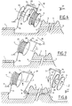
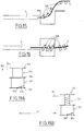
- FIG. 11 shows schematically and in an axis view the structure of the bearing of the tube 64 at the inlet 4 of the passage 3 and of the tube 82 at the outlet 5 of this same passage.
- the references corresponding to the part upstream of the passage 3 are shown without parentheses while the references of the part downstream of the passage 3 are represented in parentheses.
- This figure 11 shows the tube 64, (82) placed in the rollers 68, 69, (86, 87) of the two respective pairs of three rollers arranged in a triangle. Each group of rollers is carried by a frame 90 in the form of a lyre. This sectional view shows that the tube 64, (82) is provided with a removable part 91 for the extraction of the cable 1 (1A).
- FIG. 12 is a view similar to that of FIG. 11 showing the toothed wheels 65, 83 carried by the end of the tube 64, 82. These toothed wheels are also provided with a removable segment 93. (This segment 92 is worn by the removable part 91 of the tube 64, 82).
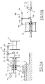
- FIG. 13A shows a variant embodiment of the assembly of FIG. 9.
- the auxiliary drum 22 is carried by a sleeve 170 by means of a ball bearing 171.
- This sleeve 170 is itself mounted at rotation in the console 172 by means of a bearing 173.
- This sleeve 170 carries at its left end a wheel 174 cooperating with the output wheel 175 of a drive motor 176.
- the sleeve 170 is thus driven in rotation .
- this sleeve is fluted and receives a splined shaft 177 emerging from the sleeve on the right side and carrying at its end the radial arm 178 of the transfer assembly 180.
- This arm 178 is provided with a transverse arm 181 carrying at each end a pulley 182, 183. It is also provided with an intermediate pulley 184 and an additional pulley 185 located at the axis.
- the cutting movement is made by telescopic movement of the splined shaft 177 in the sleeve 170 while being driven in rotation.
- This assembly also allows the transmission of the cable by a simple transformation (FIG. 13B). For this, the main reel 6 is removed and the cable is passed over the pulley 182, the intermediate pulley 184 and the additional pulley 185 to introduce it through the inlet 4 and present it in alignment with the axis of the passage 3.
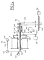
- FIG. 14 shows a variant of the reception assembly with respect to the reception assembly of FIG. 10.
- the receiving equipment is not mounted on a tube but on a splined shaft 250, one end 251 of which is housed in a bearing secured to an arm 252 controlled in translation along the double arrow J by a lead screw 253 driven by a motor 254.
- This splined shaft 251 which thus performs an axial movement, carries at its other end a radial arm 255 carrying the pulleys 256 and 257 as well as a transverse arm 258 carrying the pulley 259.
- This fluted shaft 251 crosses a fluted cylinder 260 carrying a pulley 261 connected to the pulley 262 of a motor 263 ensuring the rotation of this fluted cylinder 260 and consequently the rotation of the fluted shaft 251 and thus that of the receiving equipment 264.
- the fluted cylinder 260 is carried in a bearing 265.
- the cylinder 260 also carries the main reel 6 via a bearing 266.
- This main reel 6 is provided with a rotational drive provided by an electromagnetic coupling device 267 provided with a pulley 268 connected to the pulley 269 of a motor 270. This allows the winding torque to be applied to the main reel 6.
- Figures 15 and 16 show the guide of the cable 1 along a curved path.
- Figure 15 shows this guidance in side view, for example at the exit of passage 9 by rollers 300 in the form of diabolos arranged with an axis not perpendicular to the path to be followed by the cable 1. This appears better in the top view according to figure 16.
- the main reel 6 is any reel, which carries a certain length of cable and is non-rotating for reasons related to the previous stages of the process.
- the main reel 6 is the reel carrying the rest of the cable at the end of the burial of a length of cable in a trench. For the operation of passing through the obstacle, it is then necessary to transfer the rest of the cable from the main reel 6 to the auxiliary reel 22 before passing the cable through the obstacle.
- a variant of the method of the invention which will be described below with the aid of FIGS. 17 to 19 in its general characteristics and using FIG. 20 for an alternative embodiment, makes it possible to avoid this prior transfer by the use of a partitioned drum.
- FIG. 17 shows in perspective such a partitioned drum 700 comprising a barrel 701 extending over the entire width of the drum and which is bordered by two cheeks or flanges 702, 703 and carries an intermediate cheek or partition 704 provided with a slot 705
- the cheeks 702, 705 and 705, 703 respectively define a first compartment 706 and a second compartment 707 respectively.
- compartments can be of the same capacity or of different capacities depending on the applications of the process.
- the partitioned drum 700 is loaded beforehand with the cable distributed between the two compartments 706, 707 according to the cable installation to be carried out.
- first compartment 706 receives the part of cable intended to be buried in a trench and the second compartment 707, the part of cable which must pass through the obstacle.
- this first length of cable is the length L1
- the length of cable necessary for the passage of the obstacle as far as, for example, the junction with the connection point 27 is equal to L2 + L3.
- the point 801 of the cable 800 which is at the length L1 of its first end 802 is determined, the other strand of the cable connecting the point 801 to the second end 803 of the cable corresponding to the length L2 + L3.
- the first strand will have the reference 804 and the second strand will have the reference 805.
- the strand 804 of the cable is laid over the length L1 by burying it, for example, in a trench or by pulling it through a sheath to the connection point 26 (according to FIG. 3).
- the first compartment 706 of the drum 700 will be empty (with the exception of a work reserve corresponding for example to a layer of turns) and the second compartment 707 will still be intact.
- the compartment 707 of the drum 700 can then be used as the main drum 6 for the implementation of the method of FIG. 1.
- an assembly formed by a support receiving a drum intermediate 900 provided with means 901 for applying to the reel 900 a winding torque.
- This means is for example an electromagnetic brake, part of which is connected to the reel 900 and the other part is connected to a pulley 902 itself connected to a pulley 903 of a motor 904, the connection being made for example by a belt. 905.
- This intermediate drum 900 cooperates with an assembly 906 formed by a radial arm 907 and a transverse arm 908 carrying a pulley 909 for the passage of the cable 910 (this cable 910 is the strand 805 according to FIG. 18).
- the crew 906 also includes a second pulley 911 used during the second phase of this variant of the process.
- a second assembly 912 is provided, consisting of a radial arm 913 and a transverse arm 914, the latter carrying at each end a pulley 915, 916 and at the level of the axis. for rotation the crew 912 is provided with a pulley 917.
- the radial arm 913 is carried by a sleeve 918 mounted in a bearing 919 similar to the bearing shown in FIGS. 11 and 12 and not described in detail here.
- This second crew 912 is intended to cooperate with the first crew 906 both for the first rewinding phase to load the intermediate drum 900 and then for the second rewinding phase to load the partitioned drum 920, this partitioned drum comprises as previously a partition 921 defining with the end walls 922, 923 a first compartment 924 and a second compartment 925.
- This variant of the method is implemented as follows: At the beginning of the operations for passing the cable 910, the cable leaving the passage 3 crosses the sleeve 918 to pass over the pulleys 917, 915, 909 and arrive on the drum of the intermediate drum 900.
- the rewinding of the cable 910 on the intermediate drum 900 is carried out as has already been described above, by simultaneous rotation of the crew unwinding the strand 805 of the partitioned drum 700 (FIG. 18) until only the length of cable L2 remains in the compartment 707. As the total cable length in compartment 707 was L2 + L3, there will therefore be a cable length L3 on the intermediate reel 900.
- this double rewinding could be done independently and consist in rewinding (the order is important) the cable length L3 of the intermediate reel 900 in the compartment 925 (the reel 920 being blocked in rotation) using the crew 906 and the resumption of the remaining length L2 of the compartment 707 in the compartment 924 (the reel being braked in rotation by the device not shown mentioned above) using the crew 912.
- rewinding the order is important
- the cable length L3 of the intermediate reel 900 in the compartment 925 the reel 920 being blocked in rotation
- the crew 912 the resumption of the remaining length L2 of the compartment 707 in the compartment 924 (the reel being braked in rotation by the device not shown mentioned above) using the crew 912.
Landscapes
- Storing, Repeated Paying-Out, And Re-Storing Of Elongated Articles (AREA)
Applications Claiming Priority (2)
| Application Number | Priority Date | Filing Date | Title |
|---|---|---|---|
| FR9200473 | 1992-01-17 | ||
| FR9200473A FR2686464A1 (fr) | 1992-01-17 | 1992-01-17 | Procede d'installation d'un cable avec traversee d'obstacles a partir d'un cable de grande longueur enroule sur un touret. |
Publications (1)
| Publication Number | Publication Date |
|---|---|
| EP0551786A1 true EP0551786A1 (de) | 1993-07-21 |
Family
ID=9425725
Family Applications (1)
| Application Number | Title | Priority Date | Filing Date |
|---|---|---|---|
| EP92403595A Withdrawn EP0551786A1 (de) | 1992-01-17 | 1992-12-31 | Verfahren zum Installieren eines Kabels mit Durchquerung von Hindernissen ausgehend von einem auf einer Trommel aufgewickelten Kabel grosser Länge |
Country Status (2)
| Country | Link |
|---|---|
| EP (1) | EP0551786A1 (de) |
| FR (1) | FR2686464A1 (de) |
Cited By (2)
| Publication number | Priority date | Publication date | Assignee | Title |
|---|---|---|---|---|
| NL1013355C2 (nl) * | 1999-10-20 | 2001-04-23 | Adrianus Cornelis Johannes Kuy | Inrichting voor het opwinden van (glasvezel)kabel. |
| US10343871B2 (en) * | 2016-04-28 | 2019-07-09 | Commscope, Inc. Of North Carolina | Cable blowing apparatus and method |
Citations (4)
| Publication number | Priority date | Publication date | Assignee | Title |
|---|---|---|---|---|
| US3386682A (en) * | 1966-09-29 | 1968-06-04 | Universal Oil Prod Co | Automatic cable rewind assembly |
| EP0420721A1 (de) * | 1989-09-29 | 1991-04-03 | L'ETAT FRANCAIS représenté par LE CENTRE NATIONAL D'ETUDES DES TELECOMMUNICATIONS | Verfahren zur Doppelaufwicklung eines Kabels oder dergleichen auf der Aussenfläche einer Trommel |
| FR2653946A1 (fr) * | 1989-10-31 | 1991-05-03 | Dehe Entreprises A | Procede de deroulage et de mise en place d'un cable a fibres optiques et installation pour la mise en óoeuvre de ce procede. |
| FR2657802A1 (fr) * | 1990-02-02 | 1991-08-09 | Allugnet Andre | Centrale de devidage de fil de soudure. |
-
1992
- 1992-01-17 FR FR9200473A patent/FR2686464A1/fr active Pending
- 1992-12-31 EP EP92403595A patent/EP0551786A1/de not_active Withdrawn
Patent Citations (4)
| Publication number | Priority date | Publication date | Assignee | Title |
|---|---|---|---|---|
| US3386682A (en) * | 1966-09-29 | 1968-06-04 | Universal Oil Prod Co | Automatic cable rewind assembly |
| EP0420721A1 (de) * | 1989-09-29 | 1991-04-03 | L'ETAT FRANCAIS représenté par LE CENTRE NATIONAL D'ETUDES DES TELECOMMUNICATIONS | Verfahren zur Doppelaufwicklung eines Kabels oder dergleichen auf der Aussenfläche einer Trommel |
| FR2653946A1 (fr) * | 1989-10-31 | 1991-05-03 | Dehe Entreprises A | Procede de deroulage et de mise en place d'un cable a fibres optiques et installation pour la mise en óoeuvre de ce procede. |
| FR2657802A1 (fr) * | 1990-02-02 | 1991-08-09 | Allugnet Andre | Centrale de devidage de fil de soudure. |
Cited By (3)
| Publication number | Priority date | Publication date | Assignee | Title |
|---|---|---|---|---|
| NL1013355C2 (nl) * | 1999-10-20 | 2001-04-23 | Adrianus Cornelis Johannes Kuy | Inrichting voor het opwinden van (glasvezel)kabel. |
| US10343871B2 (en) * | 2016-04-28 | 2019-07-09 | Commscope, Inc. Of North Carolina | Cable blowing apparatus and method |
| EP3449540A4 (de) * | 2016-04-28 | 2019-07-24 | CommScope, Inc. of North Carolina | Kabelblasvorrichtung und -verfahren |
Also Published As
| Publication number | Publication date |
|---|---|
| FR2686464A1 (fr) | 1993-07-23 |
Similar Documents
| Publication | Publication Date | Title |
|---|---|---|
| US6032449A (en) | Process and device for splicing an optical cable to the conductor strand of an aerial line | |
| EP0009058B1 (de) | Aufhängevorrichtung für eine Bühne zur Instandhaltung von Fassaden | |
| EP0687048B1 (de) | Verfahren und Vorrichtung zum Verlegen eines unterirdischen Fernmeldekabels | |
| FR2595114A1 (fr) | Procede et dispositif pour guider un tuyau souple de distribution de beton lors d'un renforcement de roche par fils metalliques noyes dans du beton | |
| EP0420721B1 (de) | Verfahren zur Doppelaufwicklung eines Kabels oder dergleichen auf der Aussenfläche einer Trommel | |
| EP0551786A1 (de) | Verfahren zum Installieren eines Kabels mit Durchquerung von Hindernissen ausgehend von einem auf einer Trommel aufgewickelten Kabel grosser Länge | |
| EP0141105B1 (de) | Einrichtung für das Verseilen von Bewehrungsdrähten um eine Kabelseele herum und durch diese Einrichtung ausgeführtes Verfahren | |
| US4890957A (en) | Cable laying apparatus | |
| NZ215550A (en) | Unwinding cable from reel core outwards, passing it through an aperture then rewinding it on another reel | |
| FR2765144A1 (fr) | Dispositif d'engagement de bandes pour machines rotatives a imprimer | |
| FR2504303A1 (fr) | Dispositif de transport de bande magnetique | |
| EP2327833B1 (de) | Vorrichtung zum Schutz eines länglichen Teils wie eines Kabels oder ein Rohrs | |
| EP1932042B1 (de) | Maschine zum legen eines optischen kabels um eine suspensionsader herum | |
| EP1715554A2 (de) | Verfahren und tragbares Gerät zur Voreinziehung eines Mantels | |
| FR2509275A1 (fr) | Dispositif de controle de la surlongueur d'au moins une fibre optique lors de sa pose | |
| FR2653946A1 (fr) | Procede de deroulage et de mise en place d'un cable a fibres optiques et installation pour la mise en óoeuvre de ce procede. | |
| EP0759004B1 (de) | Verfahren und vorrichtung zum wickelförmigen speichern von kabeln oder dergleichen | |
| FR2687501A1 (fr) | Dispositif et procedes d'assemblage de conducteurs electriques. | |
| FR2717959A1 (fr) | Procédé pour la mise en place d'un câble de télécommunications dans une conduite de grande longueur. | |
| NL1013355C2 (nl) | Inrichting voor het opwinden van (glasvezel)kabel. | |
| KR100280077B1 (ko) | 광케이블 포설기 | |
| FR2702099A1 (fr) | Dispositif pour la traction et l'enroulement d'un câble, notamment pour télécommunications. | |
| FR2573275A1 (fr) | Machine et procede pour enfiler des fils dans un conduit | |
| EP0039963B1 (de) | Turmdrehkran | |
| FR2533688A1 (fr) | Dispositif de controle de la surlongueur d'une fibre optique dans un element porteur |
Legal Events
| Date | Code | Title | Description |
|---|---|---|---|
| PUAI | Public reference made under article 153(3) epc to a published international application that has entered the european phase |
Free format text: ORIGINAL CODE: 0009012 |
|
| AK | Designated contracting states |
Kind code of ref document: A1 Designated state(s): AT BE CH DE DK ES FR GB GR IE IT LI LU MC NL PT SE |
|
| STAA | Information on the status of an ep patent application or granted ep patent |
Free format text: STATUS: THE APPLICATION IS DEEMED TO BE WITHDRAWN |
|
| 18D | Application deemed to be withdrawn |
Effective date: 19940122 |