EP0551183A1 - Erfassungs- und Alarmanlage zum Erfassen einer kurzgeschossenen oder unterbrochenen Schaltung - Google Patents
Erfassungs- und Alarmanlage zum Erfassen einer kurzgeschossenen oder unterbrochenen Schaltung Download PDFInfo
- Publication number
- EP0551183A1 EP0551183A1 EP93300053A EP93300053A EP0551183A1 EP 0551183 A1 EP0551183 A1 EP 0551183A1 EP 93300053 A EP93300053 A EP 93300053A EP 93300053 A EP93300053 A EP 93300053A EP 0551183 A1 EP0551183 A1 EP 0551183A1
- Authority
- EP
- European Patent Office
- Prior art keywords
- terminal
- main
- switch
- alarm
- loop
- Prior art date
- Legal status (The legal status is an assumption and is not a legal conclusion. Google has not performed a legal analysis and makes no representation as to the accuracy of the status listed.)
- Withdrawn
Links
Images
Classifications
-
- G—PHYSICS
- G08—SIGNALLING
- G08B—SIGNALLING OR CALLING SYSTEMS; ORDER TELEGRAPHS; ALARM SYSTEMS
- G08B29/00—Checking or monitoring of signalling or alarm systems; Prevention or correction of operating errors, e.g. preventing unauthorised operation
- G08B29/02—Monitoring continuously signalling or alarm systems
- G08B29/06—Monitoring of the line circuits, e.g. signalling of line faults
-
- G—PHYSICS
- G08—SIGNALLING
- G08B—SIGNALLING OR CALLING SYSTEMS; ORDER TELEGRAPHS; ALARM SYSTEMS
- G08B13/00—Burglar, theft or intruder alarms
- G08B13/22—Electrical actuation
Definitions
- the present invention relates to a detecting and alarming system for detecting shortcircuited or broken circuit.
- a conventional alarm circuit such as connected between a security company and a client may be cut once intruted by a thief or robber, thereby losing its alarming effect or chance for asking help.
- a detecting and alarming system including a main alarm circuit provided in a headquarter control center, at least a terminal alarm circuit provided at a local station, and at least a connecting loop connecting the main alarm circuit and each terminal alarm circuit, whereby upon a cutting or a shortcircuiting of the connecting loop between the headquarter control center and the local station, an alarm will be actuated for warning the breaking or shortcircuiting situation.
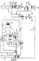
- the single drawing figure shows a circuit of the detecting and alarming system in accordance with the present invention.
- the present invention comprises: a main alarm circuit 1, at least a terminal alarm circuit 2, and at least a connecting loop 3 connecting the main alarm circuit 1 and each terminal alarm circuit 2.
- the main alarm circuit 1 may be provided in a headquarter control center of a security company or a control room of a multi-story building, a plant or a management head office; whereas the terminal alarm circuit 2 may be provided at a local station of a client's room monitored by a security company or a floor control desk (or counter) of a multi-story building.
- a plurality of terminal alarm circuits 2 may be connected in parallel with the main alarm circuit 1 through each connecting loop 3.
- the main alarm circuit 1 includes: a main power source of alternative current 11 having a main power switch 111 for an on-off control of the power source, a first transformer 12 respectively converting a high input voltage such as of 110 volts to a first lower output voltage such as of 24 volts (122) for powering the connecting loop 3 and converting the high input voltage to a second lower voltage such as 12 volts (123) for powering a mian alarm 16, a first rectifier 13 converting an input alternative current to be a direct current for powering the main alarm 16, a choke 14, which is connected between a positive pole and a negative pole of the connecting loop 3 and powered for normally electromagnetically attracting a first contactor switch 141, which normally closes the main alarm circuit as connected across two poles of the first rectifier 13, for disconnecting the main alarm circuit 1, an automatic holding circuit 15 including an electromagnetic coil 150 and a second contactor switch 151 connected in series across two output poles of the first rectifier 13 with the electromagnetic coil 150 further connected in series with the first contactor switch 141, and a
- the alarm 16 Since the first contactor switch 141 is originally closed (on) to close the main alarm circuit 1 when the connecting loop 3 is not powered, and in the situation when the loop 3 is cut by a thief or an intruder to disconnect the power supply, the alarm 16 will be sounding for security detecting purpose.
- Each terminal alarm circuit 2 includes: a terminal power source of alterative current 21, which may be supplied by a municipal power supply source as same as that for the main alarm circuit 1, having a terminal power switch 211 for on/off control of the power source 21, a second transformer 22 having primary windings 221 and secondary windings 222 for converting a high input voltage of 110 volts to a low output voltage of 12 volts (222), which is then rectified by a second rectifier 23 to be a direct current for powering a terminal alarm 26, a second relay 24 including an electromagnetic coil connected across two poles of the connecting loop 3 operatively attracting a terminal contactor switch 241, which is normally closed for closing two poles across the primary windings 221 of the terminal power source 21, for opening the terminal contactor switch 241 when the second relay 24 is actuated and powered by the connecting loop 3, and a third relay 25 connected across two output poles of the second rectifier 23 and operatively closing a relay switch 251 connected between the second rectifier 23 and the terminal alarm 26 for actuating the
- the connecting loop 3 includes: a set of secondary windings 122 for directing an input transformed low voltage current from the first transformer 12 for powering the loop 3 normally, a diode 34 and a sensor contactor switch 331 normally closed and connected in series with the diode 34 connected across two poles of the connecting loop, and a sensor 33 provided in a proximity to the loop 3 in cooperatiion with the sensor contactor switch 331 for operatively sensing an intruder for switching off the sensor contactor switch 331 for disconnecting the loop 3 for actuating the alarms 16, 26.
- the sensor 33 may be a magnet mounted on a door and the sensor contactor switch 331 may be a reed switch mounted on a door frame, with the reed switch being normally closed as attracted by the magnet when closing the door for approximating the magnet to the reed switch, whereby upon an opening of the door such as opened by an intruder to separate the magnet from the reed switch, the reed switch will be opened for actuating the alarms 16, 26.
- the present invention is provided with the automatic holding circuit 15 for ensuring an affirmative detecting job, whereby once upon an opening of the door by an intruder who immediately closes the door trying to deactivate the alarm sounding, the first opening of the door will disconnect the power of the loop 3 to close the contactor switch 141 and close the circuit of the coil 150 which will electromagnetically attract the second contactor switch 151 for powering and sounding the alarm 16.
- a positive pole of the rectified power supply of the main alarm circuit 1 is connected, through switch 141 of choke 14, and the coil 150, to the negative pole and the positive pole is also connected through the contactor switch 151 in parallel with the contactor switch 141, an input pole of the coil 150, two poles of the alarm 16 and then to the negative pole of the rectified power supply, therefore ensuring automatic circuit holding effect by the automatic holding circuit of the present invention.
- either switch 111 or 211 may be switched off to disconnect the power supply to the system until any intrusion problem is overcome and then the switches 111, 211 must be reset to be ready for detecting service.
- capacitors are provided in this invention each capa citor connected in parallel with a coil for stabilizing voltage and for filtering off any interference waves in the circuits.
- the present invention may also be used for detecting a breaking wire within a plurality of wires used for maintenance work for checking a breaking condition for electrical wires.
- the present invention provides a detecting and alarming system which may be used for security purpose, such that if a thief breaks the loop 3 trying to disconnect the alarm system circuit or even shortcircuits the alarm circuit, the alarm either at headquarter control center (such as a security company) or local station (such as a client's home) will be operatively actuated for giving warning to the relevant personnels for preventing being stolen.
- headquarter control center such as a security company
- local station such as a client's home
- the present invention may be modified to have optical alarm devices, such as a light emitting diode 143 connected across the two poles of the relay 17 for an illuminative warning such as in case of a shortcircuiting of the loop 3 by an intruder.
- optical alarm devices such as a light emitting diode 143 connected across the two poles of the relay 17 for an illuminative warning such as in case of a shortcircuiting of the loop 3 by an intruder.
Landscapes
- Physics & Mathematics (AREA)
- General Physics & Mathematics (AREA)
- Engineering & Computer Science (AREA)
- Computer Security & Cryptography (AREA)
- Burglar Alarm Systems (AREA)
Applications Claiming Priority (2)
| Application Number | Priority Date | Filing Date | Title |
|---|---|---|---|
| US07/817,321 US5200734A (en) | 1992-01-06 | 1992-01-06 | Detecting and alarming system for detecting shortcircuited or broken circuit |
| US817321 | 1992-01-06 |
Publications (1)
| Publication Number | Publication Date |
|---|---|
| EP0551183A1 true EP0551183A1 (de) | 1993-07-14 |
Family
ID=25222814
Family Applications (1)
| Application Number | Title | Priority Date | Filing Date |
|---|---|---|---|
| EP93300053A Withdrawn EP0551183A1 (de) | 1992-01-06 | 1993-01-06 | Erfassungs- und Alarmanlage zum Erfassen einer kurzgeschossenen oder unterbrochenen Schaltung |
Country Status (2)
| Country | Link |
|---|---|
| US (1) | US5200734A (de) |
| EP (1) | EP0551183A1 (de) |
Cited By (4)
| Publication number | Priority date | Publication date | Assignee | Title |
|---|---|---|---|---|
| US6656156B2 (en) | 1999-02-03 | 2003-12-02 | Scimed Life Systems, Inc. | Dual surface protection coating for drug delivery balloon catheters and stents |
| US9038675B2 (en) | 2009-05-29 | 2015-05-26 | Lts Lohmann Therapie-Systeme Ag | Cylinder-piston unit suitable for storing injection solutions for a needle-free injector and method for the bubble-free automatic or manual filling of the cylinder-piston unit, also under atmospheric pressure |
| CN107968480A (zh) * | 2017-10-24 | 2018-04-27 | 国家电网公司 | 一种电力应急自动化管理装置 |
| KR20180135614A (ko) * | 2017-06-13 | 2018-12-21 | 주식회사 엘지화학 | 소리 센서를 통한 컨텍터 진단 시스템 및 방법 |
Families Citing this family (5)
| Publication number | Priority date | Publication date | Assignee | Title |
|---|---|---|---|---|
| US5389916A (en) * | 1993-06-28 | 1995-02-14 | Chen; Sheng-Chuan | Simplified shortcircuiting and circuit-breaking alarm means for planar or linear conductors |
| DE4325732C2 (de) * | 1993-07-30 | 2003-04-24 | Bosch Gmbh Robert | Verfahren zur potentialfreien Überwachung von Ringleitungen |
| US7283055B2 (en) * | 2004-07-10 | 2007-10-16 | Frank Theodore Didik | Electrified cover safeguard |
| CN106950458A (zh) * | 2017-03-15 | 2017-07-14 | 国家电网公司 | 低压单相线路短路及断路检测装置 |
| CN107085189A (zh) * | 2017-06-08 | 2017-08-22 | 中国工商银行股份有限公司 | Ups电源故障监控装置 |
Citations (6)
| Publication number | Priority date | Publication date | Assignee | Title |
|---|---|---|---|---|
| FR952950A (fr) * | 1947-08-22 | 1949-11-28 | Système de sécurité combiné par alerte à distance et action locale | |
| US3200393A (en) * | 1962-06-18 | 1965-08-10 | Emmett J Worley | Electric burglar alarm system with exit and entry delay |
| US3626403A (en) * | 1968-04-29 | 1971-12-07 | Goodwin Alfred George Ive | Protective systems and apparatus therefor |
| FR2195020A1 (de) * | 1972-08-02 | 1974-03-01 | Lewis Nigel | |
| GB1351748A (en) * | 1970-07-16 | 1974-05-01 | Bardic Systems Ltd | Electric alarm systems |
| FR2410315A1 (fr) * | 1977-11-24 | 1979-06-22 | Muller Charles | Dispositif d'alarme pour la protection d'un immeuble contre l'effraction |
Family Cites Families (4)
| Publication number | Priority date | Publication date | Assignee | Title |
|---|---|---|---|---|
| US3474299A (en) * | 1964-03-13 | 1969-10-21 | Westinghouse Electric Corp | Relay circuit for communication apparatus |
| US3653041A (en) * | 1969-12-02 | 1972-03-28 | Gulf & Western Syst Co | Annunciator system |
| US3678509A (en) * | 1970-07-30 | 1972-07-18 | Multra Guard Inc | Security alarm system |
| US4435700A (en) * | 1978-12-01 | 1984-03-06 | Alley Patrick H | Event detection and indication system |
-
1992
- 1992-01-06 US US07/817,321 patent/US5200734A/en not_active Expired - Fee Related
-
1993
- 1993-01-06 EP EP93300053A patent/EP0551183A1/de not_active Withdrawn
Patent Citations (6)
| Publication number | Priority date | Publication date | Assignee | Title |
|---|---|---|---|---|
| FR952950A (fr) * | 1947-08-22 | 1949-11-28 | Système de sécurité combiné par alerte à distance et action locale | |
| US3200393A (en) * | 1962-06-18 | 1965-08-10 | Emmett J Worley | Electric burglar alarm system with exit and entry delay |
| US3626403A (en) * | 1968-04-29 | 1971-12-07 | Goodwin Alfred George Ive | Protective systems and apparatus therefor |
| GB1351748A (en) * | 1970-07-16 | 1974-05-01 | Bardic Systems Ltd | Electric alarm systems |
| FR2195020A1 (de) * | 1972-08-02 | 1974-03-01 | Lewis Nigel | |
| FR2410315A1 (fr) * | 1977-11-24 | 1979-06-22 | Muller Charles | Dispositif d'alarme pour la protection d'un immeuble contre l'effraction |
Cited By (5)
| Publication number | Priority date | Publication date | Assignee | Title |
|---|---|---|---|---|
| US6656156B2 (en) | 1999-02-03 | 2003-12-02 | Scimed Life Systems, Inc. | Dual surface protection coating for drug delivery balloon catheters and stents |
| US9038675B2 (en) | 2009-05-29 | 2015-05-26 | Lts Lohmann Therapie-Systeme Ag | Cylinder-piston unit suitable for storing injection solutions for a needle-free injector and method for the bubble-free automatic or manual filling of the cylinder-piston unit, also under atmospheric pressure |
| KR20180135614A (ko) * | 2017-06-13 | 2018-12-21 | 주식회사 엘지화학 | 소리 센서를 통한 컨텍터 진단 시스템 및 방법 |
| CN107968480A (zh) * | 2017-10-24 | 2018-04-27 | 国家电网公司 | 一种电力应急自动化管理装置 |
| CN107968480B (zh) * | 2017-10-24 | 2021-01-08 | 国家电网公司 | 一种电力应急自动化管理装置 |
Also Published As
| Publication number | Publication date |
|---|---|
| US5200734A (en) | 1993-04-06 |
Similar Documents
| Publication | Publication Date | Title |
|---|---|---|
| US5640141A (en) | Surveillance and alarm device for room spaces | |
| US5365145A (en) | Emergency lighting system | |
| US3594584A (en) | Telemetry circuit for an ac power system | |
| US6078257A (en) | Current detector flood light lamp removal alarm | |
| US4199754A (en) | Circuit for an emergency lighting and fire detector system | |
| US4103294A (en) | Intruder deterrent apparatus and method | |
| US4206450A (en) | Fire and intrusion security system | |
| US4808972A (en) | Security system with false alarm inhibiting | |
| US5200734A (en) | Detecting and alarming system for detecting shortcircuited or broken circuit | |
| US4059843A (en) | Overload and ground fault protective device | |
| US3974492A (en) | Alarm system | |
| EP0951001A2 (de) | Detektierungsvorrichtung und Alarmsystem | |
| US3978466A (en) | Alarm system including remote signalling means | |
| US4074248A (en) | Dual operating control circuits for intrusion detection systems | |
| US2701874A (en) | Burglar alarm system | |
| US5014039A (en) | Door answering and intruder alert apparatus and method | |
| US3813662A (en) | Electrical alarm systems | |
| CA1127705A (en) | Electric lighting installation | |
| US4887072A (en) | Alarm apparatus | |
| US3766537A (en) | A.c. powered surveillance system | |
| CA1207400A (en) | System for detecting an alarm | |
| US5654691A (en) | Auxiliary backup device of burglary alarm system | |
| US3769556A (en) | Magnetic actuated switch apparatus including shunt | |
| CN111726579B (zh) | 校园安防监控系统 | |
| WO1996002902A1 (en) | Emergency control apparatus |
Legal Events
| Date | Code | Title | Description |
|---|---|---|---|
| PUAI | Public reference made under article 153(3) epc to a published international application that has entered the european phase |
Free format text: ORIGINAL CODE: 0009012 |
|
| AK | Designated contracting states |
Kind code of ref document: A1 Designated state(s): DE FR GB IT |
|
| 18D | Application deemed to be withdrawn |
Effective date: 19940117 |