EP0551171B1 - Method and apparatus for providing visual indication in an electric cooking appliance - Google Patents
Method and apparatus for providing visual indication in an electric cooking appliance Download PDFInfo
- Publication number
- EP0551171B1 EP0551171B1 EP93300021A EP93300021A EP0551171B1 EP 0551171 B1 EP0551171 B1 EP 0551171B1 EP 93300021 A EP93300021 A EP 93300021A EP 93300021 A EP93300021 A EP 93300021A EP 0551171 B1 EP0551171 B1 EP 0551171B1
- Authority
- EP
- European Patent Office
- Prior art keywords
- heater
- switch
- heating element
- visible radiation
- lamp
- Prior art date
- Legal status (The legal status is an assumption and is not a legal conclusion. Google has not performed a legal analysis and makes no representation as to the accuracy of the status listed.)
- Expired - Lifetime
Links
- 238000010411 cooking Methods 0.000 title claims abstract description 17
- 230000000007 visual effect Effects 0.000 title claims abstract description 14
- 238000000034 method Methods 0.000 title claims description 8
- 238000010438 heat treatment Methods 0.000 claims abstract description 117
- 230000005855 radiation Effects 0.000 claims abstract description 54
- 238000009998 heat setting Methods 0.000 claims abstract description 9
- 230000007935 neutral effect Effects 0.000 description 7
- 230000000694 effects Effects 0.000 description 6
- 238000013021 overheating Methods 0.000 description 2
- 230000000750 progressive effect Effects 0.000 description 2
- 230000005611 electricity Effects 0.000 description 1
- 239000012858 resilient material Substances 0.000 description 1
- 238000001228 spectrum Methods 0.000 description 1
- 239000010409 thin film Substances 0.000 description 1
Images

Classifications
-
- F—MECHANICAL ENGINEERING; LIGHTING; HEATING; WEAPONS; BLASTING
- F24—HEATING; RANGES; VENTILATING
- F24C—DOMESTIC STOVES OR RANGES ; DETAILS OF DOMESTIC STOVES OR RANGES, OF GENERAL APPLICATION
- F24C15/00—Details
- F24C15/10—Tops, e.g. hot plates; Rings
- F24C15/102—Tops, e.g. hot plates; Rings electrically heated
- F24C15/106—Tops, e.g. hot plates; Rings electrically heated electric circuits
-
- F—MECHANICAL ENGINEERING; LIGHTING; HEATING; WEAPONS; BLASTING
- F24—HEATING; RANGES; VENTILATING
- F24C—DOMESTIC STOVES OR RANGES ; DETAILS OF DOMESTIC STOVES OR RANGES, OF GENERAL APPLICATION
- F24C7/00—Stoves or ranges heated by electric energy
- F24C7/08—Arrangement or mounting of control or safety devices
- F24C7/082—Arrangement or mounting of control or safety devices on ranges, e.g. control panels, illumination
Definitions
- the present invention relates to a method of and an apparatus for providing a visual indication of a change of power output in a heater of an electric cooking appliance that the heater is being switched from one power output to another.
- the heaters are provided with two or more heating elements which are connected in various configurations to give a plurality, for example six, of different heating power outputs.
- the heating elements may be connected in a number of different series and parallel arrangements, possibly with the use of rectifier means and/or a bimetallic switch device to adjust the power output of one or more of the heating elements and/or possibly with the application of more than one voltage to one or more of the heating elements to give different power outputs of the heating elements, see, for instance the GB-A-2 042 291.
- heating elements for example three heating elements
- the effects of any visible changes in the radiation from the coils are small. This is because the coils increase and decrease slowly in brightness relative to a typical speed of rotation of a manually operated control knob of the multi-position switch and because the coils do not give off significant amounts of visible radiation at low power outputs.
- radiant heaters have incorporated heating elements in the form of infra-red lamps. Initially four lamps were used, but subsequently radiant heaters with three, two and one infra-red lamp have been introduced. Although the major part of the radiation emitted by the infra-red lamps is in the infra-red region of the spectrum, a significant part of the radiation is visible. In the case of radiant heaters with four infra-red lamps it was relatively straightforward, by connecting the lamps in various parallel and series configurations, to obtain six progressive power output levels which corresponded with progressive visible radiation from the lamps. Moreover, the change in visible radiation and in power output is fast and virtually instantaneous at high power output levels.
- a method for providing a visual indication in a heater of an electric cooking appliance the appliance incorporating a user-operable multi-position switch for switching the heater from one power output to another, the heater incorporating at least one heating element which is capable of emitting a significant amount of visible radiation, wherein the at least one heating element is de-energised and subsequently re-energised as the heater is switched from one power output to another.
- apparatus for providing a visual indication in a heater of an electric cooking appliance, the appliance incorporating a user-operable multi-position switch for switching the heater from one power output to another, the heater incorporating at least one heating element which is capable of emitting a significant amount of visible radiation, the apparatus including means for de-energising and re-energising the at least one heating element as the heater is switched from one power output to another.
- the heater may incorporate at least one further heating element which, in use, does not emit a significant amount of visible radiation.
- the at least one heating element is capable of emitting a plurality of distinct levels of visible radiation fewer than the plurality of distinct heat settings of the heater selectable from the multi-position switch
- the at least one heating element may be de-energised and subsequently re-energised only between adjacent heat settings in which there is no substantial change in the level of visible radiation.
- the level of visible radiation from the at least one heating element does not reduce as the heat output setting of the heater increases.
- the multi-position switch incorporates a plurality of rotatable cams for switching the heater from one power output to another
- at least one of the cams may be profiled such as to de-energise and to sunsequently re-energise the at least one heating element as the heater is switched from one power output to another.
- Figure 1 shows a switch arrangement of a multi-position switch and a radiant heater assembly of an electric cooking appliance.
- the radiant heater comprises a single infra-red lamp L and two resistive heating elements R1 and R2.
- the switch arrangement has six heat settings and incorporates seven sets of contacts C1, C2, C3, C4, C5, C6 and C7 which are opened or closed in accordance with Table 1 shown below:
- Table 1 Contacts Switch position 6 5 4 3 2 1 C1 X C2 X X C3 X X X X X C4 X X C5 X C6 X X X C7 X X X X contact closed
- a bimetallic relay B includes two series-connected heating elements r1 and r2, for example in the form of a thick- or thin-film resistor provided with a tap along its length, and a bimetallic switch S.
- different heating powers, and thus duty cycles can be obtained by energising different length portions of the resistor, selected by appropriate switching.
- any variations in the value of the resistor will affect each of its sections proportionately.
- the bimetallic relay is in effect a mechanically non-adjustable energy regulator and operates by virtue of electric current passing through the heating elements r2 and possibly also r1 and causing a bimetallic member, such as a bimetallic strip or bimetallic disc, to be heated.
- a bimetallic member such as a bimetallic strip or bimetallic disc
- the switch opens cutting off the flow of current and causing the bimetallic member to cool and to close the switch.
- a thermal cut-out device T is provided to prevent overheating and can be positioned elsewhere in the circuit if desired.
- switch position 6 which gives maximum power
- the contacts C3, C5 and C7 are closed and the resistive heating elements R1 and R2 are connected in series with one another and are connected in parallel with the lamp L.
- switch position 5 the contacts C2, C3, C4 and C7 are closed and the resistive heating element R1 is connected in series with the lamp L, while the resistive heating element R2 is connected in parallel with the combination of the lamp L and the resistive heating element R1. Because the contact C2 is closed, power passes to the bimetallic relay B by way of the heating element r2 in order to operate the bimetallic relay B at a first duty cycle, of say 25 to 30 percent of maximum power.
- switch position 4 the contacts C4 and C7 are closed and the resistive heating element R1 is connected in series with the lamp L.
- the contacts C3 and C6 are closed and the lamp L is connected in series with both the resistive heating elements R1 and R2.
- switch positions 2 and 1 contacts C3 and C6 are closed and the lamp L is connected in series with both the resistive heating elements R1 and R2 as in switch position 3. Additionally, in switch position 2, contact C1 is closed allowing power to pass through the heating elements r1 and r2 in series to operate the bimetallic relay at a second duty cycle of say 50 to 60 per cent of maximum. In switch position 1, contact C2 is closed allowing power to pass through the heating element r2 so as to operate the bimetallic relay at the first duty cycle.
- the second duty cycle is higher than the first duty cycle because the heat generated to operate the bimetallic member is lower when power passes through the two heating elements r1 and r2 in series as compared with the single heating element r2 because the two heating elements in series have a higher electrical resistance and generate less heat, thus heating the bimetallic member more slowly and allowing the switch to remain closed for longer, than with the single heating element.
- switch position 6 the lamp L is operating at full power and the visible radiation is at a maximum.
- switch position 5 the resistive heating element R1 is connected in series with the lamp L and the visible radiation is reduced compared with switch position 6.
- switch position 4 the resistive heating element R1 is still connected in series with the lamp L and there is no change in visible radiation compared with switch position 5.
- switch position 3 the lamp L is connected in series with both resistive heating elements R1 and R2 and the visible radiation is reduced compared with switch position 4.
- switch positions 2 and 1 the lamp L is still connected in series with the resistive heating elements R1 and R2.
- a typical multi-position switch is shown in Figure 2 and comprises a housing 10 containing a plurality of profiled cams 12 mounted on, or moulded integrally with, a rotatable spindle 14.
- the spindle 14 is rotatable by means of a control knob 16.
- a movable arm 18 Positioned adjacent to each of the cams 12 is a movable arm 18 for operating a set of switch contacts such as those illustrated diagrammatically in Figure 1.
- the switch contacts are illustrated in more detail in Figures 3 and 4.
- one of the contacts 20 is stationary and the other contact 22 is movable and is positioned at the end of arm 18, both contacts 20 and 22 being mounted on the switch housing 10.
- the arm 18 is configured to provide an upstanding, generally inverted V-shaped, portion 26 for engaging with the relevant cam 12.
- the arm 18 is made of a resilient material biasing the upstanding portion 26 into engagement with the cam 12, while in Figure 4 the arm 18 is provided with a hinge 28 on that side of the upstanding portion 26 remote from the contact 22 and a spring 30 acts between the housing 10 and the arm 18 to urge the upstanding portion into engagement with the cam 12.
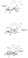
- Figures 5 and 6 illustrate in more detail the engagement between the upstanding portion 26 of the arm 18 carrying the switch contact 22 and a cam 12.
- the cam 12 is formed with a cut-out defining a recessed portion 32 which is capable of receiving the upstanding portion 26 in one position of the rotatable control knob 16 thus permitting the contact 20 and 22 to close.
- Figure 5 is merely exemplary and is included to demonstrate the method of operation of the multi-position switch.
- the cam 12 illustrated in Figure 5 would correspond to switch contacts C1 in Table 1 above which are closed only in switch position 2 and to switch contacts C5 in Table 1 above which are closed only in switch position 6. If the control knob 16, and thus the cam 12, is rotated by one index position in either direction from the position in which the contacts 20 and 22 are closed, the cam 12 will urge the upstanding portion 26 out of the recess thereby opening the contacts 20 and 22.
- the cam 12 is formed with a cut-out defining a recessed portion 34, of greater circumferential extent than the recessed portion 32, which portion 34 is capable of receiving the upstanding portion 26 in two adjacent positions of the rotatable control knob 16 thus permitting the contact 20 and 22 to close in both those positions.
- Figure 6 is merely exemplary and is included to demonstrate the method of operation of the multi-position switch, the cam 12 illustrated in Figure 6 would correspond to switch contacts C4 in Table 1 above which are closed in adjacent switch positions 4 and 5. If the control knob 16, and thus the cam 12, is rotated clockwise from the index position shown, the cam 12 will urge the upstanding portion 26 out of the recess thereby opening the contacts 20 and 22.
- the limited number of heating element configurations for the heater illustrated in Figure 1 does not in practice permit a greater range of visible radiation for the lamp L, and thus in certain adjacent switch positions (switch positions 1, 2 and 3, subject to the bimetallic switch S being closed, and switch positions 4 and 5) there will be no change in visible radiation.
- switch positions 1, 2 and 3 subject to the bimetallic switch S being closed, and switch positions 4 and 5
- the visual indication is given by briefly de-energising the lamp when changing from one power level to another. This causes the lamp L to dim briefly and then to return to its previous brightness.
- the brief period of de-energisation does provide the user with an indication that the heater has been switched from one power output to another.
- FIG. 7 corresponds to previous Figure 6.
- the cam profile shown in Figure 7 differs from that shown in Figure 6 in that between the two adjacent positions within the recess 34 there is a protrusion 36.
- the control knob 16 is moved from one index position within the recess 34 to the other index position within the recess 34 the upstanding portion 26 of the arm 18 is briefly urged out of the recess thereby briefly opening the contacts 20 and 22 and de-energising the lamp L.
- protrusion 36 could be arranged on the cam 12 corresponding to contacts C4 to briefly de-energise the lamp L between switch positions 4 and 5, it is in practice preferable to modify the cam corresponding to contacts C7 in order to minimise the current interrupted by the opening of the contacts 20 and 22.
- each index position can be separated from the next by a protrusion 36 causing the contacts 20 and 22 to be briefly opened and the lamp L de-energised between each adjacent pair of index positions within the recess 34.
- a protrusion 36 in the recess of the cam 12 corresponding to switch contacts C6 it is possible briefly to open the contacts 20 and 22 and thus briefly to de-energise the lamp L between switch positions 1 and 2 and between switch positions 2 and 3.
- protrusions 36 It would not normally be desirable to provide unnecessary protrusions, such as protrusions 36, in a recess of the cam profile since this would cause unnecessary opening of the contacts and give rise to unnecessary wear of the contacts and in the switch mechanism. It can also reduce the service life of the heating elements of the radiant heater. Thus it is not essential, and may well be disadvantageous, to provide protrusions between all adjacent positions within the recesses of all the cams in the multi-position switch.
- Figure 8 shows a switch arrangement of a multi-position switch having eight heat positions in conjunction with a radiant heater assembly of an electric cooking appliance.
- the bimetallic relay B includes a heating coil r3 and bimetallic switch S.
- a voltage dropping resistor r4 is connected between contact C1 and the bimetallic relay B.
- a thermal cut-out device T is provided to prevent overheating and can be positioned elsewhere in the circuit if desired.
- switch position 6 the contacts C2, C3, C6 and C7 are closed.
- the resistive heating element R1 is connected in series with the lamp L, while the resistive heating element R2 is connected in parallel with the combination of the lamp L and the resistive heating element R1, but in switch position 6 power passes directly to the bimetallic relay B which therefore operates at a second, lower duty cycle.
- switch position 5 the contacts C3 and C6 are closed and the resistive heating element R1 is connected in series with the lamp L.
- switch position 4 the contacts C4, C5 and C7 are closed and the lamp L is connected in series with the resistive heating element R2.
- switch position 3 the contacts C4 and C7 are closed and the lamp L is connected in series with both the resistive heating elements R1 and R2.
- switch positions 2 and 1 contacts C4 and C7 are closed and the lamp L is connected in series with both the resistive heating elements R1 and R2 as in switch position 3. Additionally, in switch position 2, contact C1 is closed allowing power to pass through the voltage dropping resistor r4 and then through the heating coil r3 and to operate the bimetallic relay at the first duty cycle. In switch position 1, contact C2 is closed allowing power to pass directly to the heating coil r3 so as to operate the bimetallic relay at the second duty cycle. As noted above, the value of the resistor r4 is selected so that the power flowing through the heating coil r3 in switch position 1 is higher than in switch position 2 and this results in a higher duty cycle of the bimetallic relay B in switch position 2 compared with switch position 1.
- switch positions 7 and 6 and 2 and 1 different voltages are created across the bimetallic relay B.
- the voltage is higher than in switch positions 7 and 2, the lower voltage being obtained by connecting a small external resistance r4 in series with the relay.
- the external resistance r4 is preferably mounted on the bimetallic relay B. It will be noted that in switch position 8, at maximum power, only one of the resistive heating elements, R2, is in use, the other heating element R1 being used in series with the lamp L as necessary at lower power levels.
- the voltage dropping resistor r4 can be replaced, if desired, by a diode.
- the use of a diode has the advantage of reducing the effect of tolerances in component values and supply voltage fluctuations.
- the use of a diode cannot eliminate supply voltage fluctuations, but the effect of such fluctuations is not compounded by the effect of tolerances in the voltage dropping resistor r4.
- switch position 8 the lamp L is operating at full power and the visible radiation is at a maximum.
- switch position 7 the resistive heating element R1 is connected in series with the lamp L and the visible radiation is reduced compared with switch position 8.
- switch positions 6 and 5 the resistive heating element R1 is still connected in series with the lamp L and there is no change in visible radiation compared with switch position 7.
- switch position 4 the lamp L is connected in series with the resistive heating element R2 and the visible radiation is reduced compared with switch position 5.
- switch position 3 the lamp L is connected in series with both resistive heating elements R1 and R2 and the visible radiation is reduced compared with switch position 4.
- switch positions 2 and 1 the lamp L is still connected in series with the resistive heating elements R1 and R2 and there is no change in visible radiation compared with switch position 3.
- switch positions 6 and 7 there is no actual change in visible radiation from the lamp L between switch positions 6 and 7, between switch positions 5 and 6, and, subject to the bimetallic switch S being closed, between switch positions 2 and 3 and between switch positions 1 and 2.
- protrusions 36 are provided on the cam corresponding to contact C6 between switch positions 6 and 7 and between switch positions 6 and 5 and on the cam corresponding to contact C7 between switch positions 3 and 2 and between switch positions 2 and 1.
- the protrusions can be provided on other cams if desired.
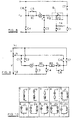
- Figure 9 shows a switch arrangement of a multi-position switch having ten heat positions in conjunction with a radiant heater assembly of an electric cooking appliance.
- the radiant heater comprises a single infra-red lamp L and two resistive heating elements R1 and R2. Also shown are seven switch contacts C1, C2, C3, C4, C5, C6 and C7 of a seven pole, eleven way switch which is provided for the user to control the heater power level, and rectifier D, which can conveniently be mounted in proximity to the switch and is used selectively to block half-cycles of a.c. power supply current to provide some of the desired heating power levels.
- Table 3 shows which switch contacts are closed for each user-selected position of the control switch; in the eleventh (off) position all contacts are open.
- Figure 10 indicates schematically which of the heating elements are actively included in the circuit for each switch position; for clarity the heating element R2 is identified in Figure 9, and also in Figure 10, by an asterisk.
- the circuit shown in Figure 9 is intended to be coupled to a two-phase a.c. electricity supply having a neutral line N and two live lines L 1 and L 2 .
- the lines L 1 and L 2 are each at a voltage V (typically 120 volts) relative to the neutral line N; in addition the phase relationship between the lines L 1 and L 2 is such that they are at a voltage 2V (typically 240 volts) relative to one another.
- V typically 120 volts
- 2V typically 240 volts
- the switch contacts are connected as follows:
- both heating elements R1 and R2 are connected in series, and in series with the rectifier D (see Figure 12).
- switch position 2 both heating elements R1 and R2 are connected in series and are connected in series with the lamp L, but without the rectifier D; thus both half-cycles of the a.c. supply are passed by the circuit, and the power dissipation is correspondingly higher.
- switch position 3 only the heating elements R1 and R2 are connected in series; since the total circuit resistance is therefore lower than with both elements R1 and R2 and lamp L together, the power dissipation is higher.
- switch position 4 the lamp L is connected in series with the heating element R1.
- the circuit in switch position 5 is similar to that in switch position 4 except that the heating element R2 is connected in series with the rectifier D and the combination of the heating element R2 and rectifier D is connected in parallel with the combination of the lamp L and the heating element R1.
- the circuit in switch position 6 is similar to that in switch position 5, except that the rectifier D is omitted (switch contact C5).
- switch position 7 the lamp L is connected in series with the heating element R1 and the combination is supplied with current via the live line L 2 and the neutral line N (switch contacts C1 and C4), at a voltage V, and the heating element R2 is connected in series with the rectifier D and this combination is supplied with current via the live lines L 1 and L 2 (switch contacts C4 and C7), at a voltage 2V.
- switch position 8 the lamp L is supplied with current via the live line L 2 and the neutral line (switch contacts C1 and C3), at a voltage V, and the heating elements R1 and R2 are connected in series and are supplied with current via the live lines L 1 and L 2 (switch contacts C3, C5 and C7), at a voltage 2V.
- Switch position 9 is similar to position 7, but with the lamp L and the heating element R1 supplied with current via the live lines L 1 and L 2 (switch contact C2), at a voltage 2V, while switch position 10 is similar to switch position 8, but with the lamp L supplied with current via the live lines L 1 and L 2 (switch contact C2), at a voltage 2V.
- switch position 10 the voltage is at 2V and the lamp L is operating at full power with the visible radiation at a maximum.
- switch position 9 the resistive heating element R1 is connected in series with the lamp L at voltage 2V and the visible radiation is reduced compared with switch position 10.
- switch position 8 the voltage is reduced to V and the visible radiation is reduced compared with switch position 9.
- switch position 7 the resistive heating element R1 is connected in series with the lamp L at voltage V and the visible radiation is reduced compared with switch position 8.
- switch positions 6, 5 and 4 the resistive heating element R1 is still connected in series with the lamp L at voltage V and there is no change in visible radiation compared with switch position 7.
- switch position 3 the lamp L is not energised, while in switch position 2 the lamp is connected in series with both resistive heating elements R1 and R2 and emits no discernible visible radiation.
- switch position 1 the lamp L is again not energised. Thus there is no actual change in visible radiation from the lamp L between switch positions 6 and 7, between switch positions 5 and 6 and between switch positions 4 and 5.
- protrusions 36 are arranged on the cam corresponding to contact C1 between switch positions 7 and 6, between switch positions 6 and 5, and between switch positions 5 and 4.
- the protrusions can be provided on other cams if desired.
Abstract
Description
- The present invention relates to a method of and an apparatus for providing a visual indication of a change of power output in a heater of an electric cooking appliance that the heater is being switched from one power output to another.
- It is well known to use a multi-position switch in conjunction with heaters, for example radiant heaters, of electric cooking appliances. The heaters are provided with two or more heating elements which are connected in various configurations to give a plurality, for example six, of different heating power outputs. The heating elements may be connected in a number of different series and parallel arrangements, possibly with the use of rectifier means and/or a bimetallic switch device to adjust the power output of one or more of the heating elements and/or possibly with the application of more than one voltage to one or more of the heating elements to give different power outputs of the heating elements, see, for instance the GB-A-2 042 291.
- When heating elements, for example three heating elements, are used in the form of coils of bare resistance wire the effects of any visible changes in the radiation from the coils are small. This is because the coils increase and decrease slowly in brightness relative to a typical speed of rotation of a manually operated control knob of the multi-position switch and because the coils do not give off significant amounts of visible radiation at low power outputs.
- More recently, radiant heaters have incorporated heating elements in the form of infra-red lamps. Initially four lamps were used, but subsequently radiant heaters with three, two and one infra-red lamp have been introduced. Although the major part of the radiation emitted by the infra-red lamps is in the infra-red region of the spectrum, a significant part of the radiation is visible. In the case of radiant heaters with four infra-red lamps it was relatively straightforward, by connecting the lamps in various parallel and series configurations, to obtain six progressive power output levels which corresponded with progressive visible radiation from the lamps. Moreover, the change in visible radiation and in power output is fast and virtually instantaneous at high power output levels.
- For radiant heaters with three or two infra-red lamps it is also possible to provide a visible radiation level that corresponds substantially to the power output level of the heater, although in some cases it may be necessary to use additional means, such as a rectifier, to adjust the power output of the heater.
- Thus the user of a cooking appliance that incorporates a radiant heater with heating elements in the form of infrared lamps has become accustomed to the heater providing a substantially accurate visual feedback of the power output of the heater.
- However, in the case of a radiant heater with only a single infra-red lamp heating element the possibilities for series and parallel configurations is severely limited, even where the infra-red lamp heating element is used in conjunction with one or more heating elements in the form of coils of bare resistance wire. Nevertheless, there is a demand for a radiant heater with a single infra-red lamp heating element and this is coupled with an expectation that the visible radiation from the heater will change progressively with changes in power output of the heater.
- It is an object of the present invention to provide a visual indication in a heater of an electric cooking appliance that the heater is being switched from one power output to another.
- According to one aspect of the present invention there is provided a method for providing a visual indication in a heater of an electric cooking appliance, the appliance incorporating a user-operable multi-position switch for switching the heater from one power output to another, the heater incorporating at least one heating element which is capable of emitting a significant amount of visible radiation, wherein the at least one heating element is de-energised and subsequently re-energised as the heater is switched from one power output to another.
- According to another aspect of the present invention there is provided apparatus for providing a visual indication in a heater of an electric cooking appliance, the appliance incorporating a user-operable multi-position switch for switching the heater from one power output to another, the heater incorporating at least one heating element which is capable of emitting a significant amount of visible radiation, the apparatus including means for de-energising and re-energising the at least one heating element as the heater is switched from one power output to another.
- The heater may incorporate at least one further heating element which, in use, does not emit a significant amount of visible radiation.
- Where the at least one heating element is capable of emitting a plurality of distinct levels of visible radiation fewer than the plurality of distinct heat settings of the heater selectable from the multi-position switch, the at least one heating element may be de-energised and subsequently re-energised only between adjacent heat settings in which there is no substantial change in the level of visible radiation.
- Preferably, the level of visible radiation from the at least one heating element does not reduce as the heat output setting of the heater increases.
- Where the multi-position switch incorporates a plurality of rotatable cams for switching the heater from one power output to another, at least one of the cams may be profiled such as to de-energise and to sunsequently re-energise the at least one heating element as the heater is switched from one power output to another.
- For a better understanding of the present invention and to show more clearly how it may be carried into effect reference will now be made, by way of example, to the accompanying drawings in which:
- Figure 1 is a diagrammatic illustration of one embodiment of a radiant heater and multi-position switch arrangement for an electric cooking appliance, the heater incorporating one infra-red lamp heating element and two coil heating elements;
- Figure 2 is a side elevational view of a multi-position switch;
- Figure 3 illustrates one form of switch contact for use in the multi-position switch shown in Figure 2;
- Figure 4 illustrates another form of switch contact for use in the multi-position switch shown in Figure 2;
- Figures 5 and 6 illustrate the engagement of the switch contact with a cam of the multi-position switch in known manner;
- Figure 7 illustrates the engagement of the switch contact with a cam of a multi-position switch according to the present invention;
- Figure 8 is a diagrammatic illustration of another embodiment of a radiant heater and multi-position switch arrangement for an electric cooking appliance, the heater incorporating one infra-red lamp heating element and two coil heating elements;
- Figure 9 is a diagrammatic illustration of a further embodiment of a radiant heater and multi-position switch arrangement for an electric cooking appliance, the heater incorporating one infra-red lamp heating element and two coil heating elements and the multi-position switch arrangement connecting the heater to a power supply system providing at least two different power supply voltages; and
- Figure 10 is a schematic illustration of the circuit arrangement which exists for each state of the multi-position switch arrangement shown in Figure 9.
- Figure 1 shows a switch arrangement of a multi-position switch and a radiant heater assembly of an electric cooking appliance. The radiant heater comprises a single infra-red lamp L and two resistive heating elements R1 and R2. The switch arrangement has six heat settings and incorporates seven sets of contacts C1, C2, C3, C4, C5, C6 and C7 which are opened or closed in accordance with Table 1 shown below:
Table 1 Contacts Switch position 6 5 4 3 2 1 C1 X C2 X X C3 X X X X X C4 X X C5 X C6 X X X C7 X X X X = contact closed - A bimetallic relay B includes two series-connected heating elements r1 and r2, for example in the form of a thick- or thin-film resistor provided with a tap along its length, and a bimetallic switch S. In this way, different heating powers, and thus duty cycles, can be obtained by energising different length portions of the resistor, selected by appropriate switching. In this case, any variations in the value of the resistor will affect each of its sections proportionately.
- The bimetallic relay is in effect a mechanically non-adjustable energy regulator and operates by virtue of electric current passing through the heating elements r2 and possibly also r1 and causing a bimetallic member, such as a bimetallic strip or bimetallic disc, to be heated. When the bimetallic member has reached a predetermined temperature the switch opens cutting off the flow of current and causing the bimetallic member to cool and to close the switch. A thermal cut-out device T is provided to prevent overheating and can be positioned elsewhere in the circuit if desired.
- In use, in
switch position 6, which gives maximum power, the contacts C3, C5 and C7 are closed and the resistive heating elements R1 and R2 are connected in series with one another and are connected in parallel with the lamp L. Inswitch position 5, the contacts C2, C3, C4 and C7 are closed and the resistive heating element R1 is connected in series with the lamp L, while the resistive heating element R2 is connected in parallel with the combination of the lamp L and the resistive heating element R1. Because the contact C2 is closed, power passes to the bimetallic relay B by way of the heating element r2 in order to operate the bimetallic relay B at a first duty cycle, of say 25 to 30 percent of maximum power. - In switch position 4, the contacts C4 and C7 are closed and the resistive heating element R1 is connected in series with the lamp L. In
switch position 3, the contacts C3 and C6 are closed and the lamp L is connected in series with both the resistive heating elements R1 and R2. - In
switch positions switch position 3. Additionally, inswitch position 2, contact C1 is closed allowing power to pass through the heating elements r1 and r2 in series to operate the bimetallic relay at a second duty cycle of say 50 to 60 per cent of maximum. Inswitch position 1, contact C2 is closed allowing power to pass through the heating element r2 so as to operate the bimetallic relay at the first duty cycle. It will be appreciated that the second duty cycle is higher than the first duty cycle because the heat generated to operate the bimetallic member is lower when power passes through the two heating elements r1 and r2 in series as compared with the single heating element r2 because the two heating elements in series have a higher electrical resistance and generate less heat, thus heating the bimetallic member more slowly and allowing the switch to remain closed for longer, than with the single heating element. - In
switch position 6 the lamp L is operating at full power and the visible radiation is at a maximum. Inswitch position 5 the resistive heating element R1 is connected in series with the lamp L and the visible radiation is reduced compared withswitch position 6. In switch position 4 the resistive heating element R1 is still connected in series with the lamp L and there is no change in visible radiation compared withswitch position 5. Inswitch position 3 the lamp L is connected in series with both resistive heating elements R1 and R2 and the visible radiation is reduced compared with switch position 4. However, inswitch positions switch positions 4 and 5, and, subject to the bimetallic switch S being closed, there is no actual change in visible radiation from the lamp L betweenswitch positions switch positions - A typical multi-position switch is shown in Figure 2 and comprises a
housing 10 containing a plurality of profiledcams 12 mounted on, or moulded integrally with, arotatable spindle 14. Thespindle 14 is rotatable by means of acontrol knob 16. Positioned adjacent to each of thecams 12 is amovable arm 18 for operating a set of switch contacts such as those illustrated diagrammatically in Figure 1. - The switch contacts are illustrated in more detail in Figures 3 and 4. In Figures 3 and 4 one of the
contacts 20 is stationary and theother contact 22 is movable and is positioned at the end ofarm 18, bothcontacts switch housing 10. Thearm 18 is configured to provide an upstanding, generally inverted V-shaped,portion 26 for engaging with therelevant cam 12. In Figure 3 thearm 18 is made of a resilient material biasing theupstanding portion 26 into engagement with thecam 12, while in Figure 4 thearm 18 is provided with ahinge 28 on that side of theupstanding portion 26 remote from thecontact 22 and aspring 30 acts between thehousing 10 and thearm 18 to urge the upstanding portion into engagement with thecam 12. - Figures 5 and 6 illustrate in more detail the engagement between the
upstanding portion 26 of thearm 18 carrying theswitch contact 22 and acam 12. - As shown in Figure 5 the
cam 12 is formed with a cut-out defining arecessed portion 32 which is capable of receiving theupstanding portion 26 in one position of therotatable control knob 16 thus permitting thecontact cam 12 illustrated in Figure 5 would correspond to switch contacts C1 in Table 1 above which are closed only inswitch position 2 and to switch contacts C5 in Table 1 above which are closed only inswitch position 6. If thecontrol knob 16, and thus thecam 12, is rotated by one index position in either direction from the position in which thecontacts cam 12 will urge theupstanding portion 26 out of the recess thereby opening thecontacts - As shown in Figure 6 the
cam 12 is formed with a cut-out defining a recessedportion 34, of greater circumferential extent than the recessedportion 32, whichportion 34 is capable of receiving theupstanding portion 26 in two adjacent positions of therotatable control knob 16 thus permitting thecontact cam 12 illustrated in Figure 6 would correspond to switch contacts C4 in Table 1 above which are closed inadjacent switch positions 4 and 5. If thecontrol knob 16, and thus thecam 12, is rotated clockwise from the index position shown, thecam 12 will urge theupstanding portion 26 out of the recess thereby opening thecontacts control knob 16 is rotated anti-clockwise by one position from the index position shown thecam 12 will not urge theupstanding portion 26 out of the recess and the switch contacts will remain closed. Only when thecontrol knob 16 is rotated anti-clockwise by two or more positions from the index position shown will thecam 12 urge theupstanding portion 26 out of the recess and open thecontacts - Clearly, where the circumferential extent of the recess extends over three or more index positions the
upstanding portion 26 will be received in thecam 12 such that thecontacts adjacent switch positions - The limited number of heating element configurations for the heater illustrated in Figure 1 does not in practice permit a greater range of visible radiation for the lamp L, and thus in certain adjacent switch positions (switch
positions - The manner in which the visual indication is given is illustrated in Figure 7 which corresponds to previous Figure 6. The cam profile shown in Figure 7 differs from that shown in Figure 6 in that between the two adjacent positions within the
recess 34 there is aprotrusion 36. Thus, when thecontrol knob 16 is moved from one index position within therecess 34 to the other index position within therecess 34 theupstanding portion 26 of thearm 18 is briefly urged out of the recess thereby briefly opening thecontacts protrusion 36 could be arranged on thecam 12 corresponding to contacts C4 to briefly de-energise the lamp L betweenswitch positions 4 and 5, it is in practice preferable to modify the cam corresponding to contacts C7 in order to minimise the current interrupted by the opening of thecontacts - Clearly, where the circumferential extent of the recess extends over three or more adjacent index positions, each index position can be separated from the next by a
protrusion 36 causing thecontacts recess 34. Thus, by providing twoprotrusions 36 in the recess of thecam 12 corresponding to switch contacts C6 it is possible briefly to open thecontacts switch positions switch positions - It would not normally be desirable to provide unnecessary protrusions, such as
protrusions 36, in a recess of the cam profile since this would cause unnecessary opening of the contacts and give rise to unnecessary wear of the contacts and in the switch mechanism. It can also reduce the service life of the heating elements of the radiant heater. Thus it is not essential, and may well be disadvantageous, to provide protrusions between all adjacent positions within the recesses of all the cams in the multi-position switch. - The present invention is not limited to electric cooking appliances in which the multi-position switches have solely six heat positions and, by way of example, Figure 8 shows a switch arrangement of a multi-position switch having eight heat positions in conjunction with a radiant heater assembly of an electric cooking appliance. As with the embodiment of Figure 1, the radiant heater of Figure 8 comprises a single infra-red lamp L and two resistive heating elements R1 and R2, while the switch arrangement incorporates seven sets of contacts C1, C2, C3, C4, C5, C6 and C7 which are opened or closed in accordance with Table 2 shown below:
Table 2 Contacts Switch Position 8 7 6 5 4 3 2 1 C1 X X C2 X X C3 X X X X C4 X X X X C5 X X C6 X X X X C7 X X X X X X X X = contact closed - In the embodiment of Figure 8, the bimetallic relay B includes a heating coil r3 and bimetallic switch S. A voltage dropping resistor r4 is connected between contact C1 and the bimetallic relay B. A thermal cut-out device T is provided to prevent overheating and can be positioned elsewhere in the circuit if desired.
- In use of the embodiment of Figure 8, in
switch position 8, which gives maximum power, the contacts C3, C5, C6 and C7 are closed and the resistive heating element R2 is connected in parallel with the lamp L. In switch position 7, the contacts C1, C3, C6 and C7 are closed and the resistive heating element R1 is connected in series with the lamp L, while the resistive heating element R2 is connected in parallel with the combination of the lamp L and the resistive heating element R1. Because the contact C1 is closed, power passes to the bimetallic relay B by way of the voltage dropping resistor r4 in order to reduce the power flowing through the heating coil r3 and to operate the bimetallic relay B at a first duty cycle that is increased with respect to the duty cycle of the bimetallic relay B when the power is connected directly to the heating coil r3 of the bimetallic relay. - In
switch position 6, the contacts C2, C3, C6 and C7 are closed. As with switch position 7, the resistive heating element R1 is connected in series with the lamp L, while the resistive heating element R2 is connected in parallel with the combination of the lamp L and the resistive heating element R1, but inswitch position 6 power passes directly to the bimetallic relay B which therefore operates at a second, lower duty cycle. Inswitch position 5, the contacts C3 and C6 are closed and the resistive heating element R1 is connected in series with the lamp L. In switch position 4, the contacts C4, C5 and C7 are closed and the lamp L is connected in series with the resistive heating element R2. Inswitch position 3, the contacts C4 and C7 are closed and the lamp L is connected in series with both the resistive heating elements R1 and R2. - In
switch positions switch position 3. Additionally, inswitch position 2, contact C1 is closed allowing power to pass through the voltage dropping resistor r4 and then through the heating coil r3 and to operate the bimetallic relay at the first duty cycle. Inswitch position 1, contact C2 is closed allowing power to pass directly to the heating coil r3 so as to operate the bimetallic relay at the second duty cycle. As noted above, the value of the resistor r4 is selected so that the power flowing through the heating coil r3 inswitch position 1 is higher than inswitch position 2 and this results in a higher duty cycle of the bimetallic relay B inswitch position 2 compared withswitch position 1. - To summarise, for
switch positions switch positions switch positions 7 and 2, the lower voltage being obtained by connecting a small external resistance r4 in series with the relay. The external resistance r4 is preferably mounted on the bimetallic relay B. It will be noted that inswitch position 8, at maximum power, only one of the resistive heating elements, R2, is in use, the other heating element R1 being used in series with the lamp L as necessary at lower power levels. - The voltage dropping resistor r4 can be replaced, if desired, by a diode. The use of a diode has the advantage of reducing the effect of tolerances in component values and supply voltage fluctuations. The use of a diode cannot eliminate supply voltage fluctuations, but the effect of such fluctuations is not compounded by the effect of tolerances in the voltage dropping resistor r4.
- In
switch position 8 the lamp L is operating at full power and the visible radiation is at a maximum. In switch position 7 the resistive heating element R1 is connected in series with the lamp L and the visible radiation is reduced compared withswitch position 8. Inswitch positions switch position 5. Inswitch position 3 the lamp L is connected in series with both resistive heating elements R1 and R2 and the visible radiation is reduced compared with switch position 4. Inswitch positions switch position 3. Thus there is no actual change in visible radiation from the lamp L betweenswitch positions 6 and 7, betweenswitch positions switch positions switch positions - Although there is no actual change in the level of visible radiation between the switch positions noted above, we have found with the arrangement illustrated in Figure 8 that it is possible to give a visual indication of a change in power output of the heater in accordance with the present invention by briefly de-energising the lamp when changing from one power level to another. This causes the lamp to dim briefly and then to return to its previous brightness. Although there is no actual change in the visible radiation from the lamp when it is energised, the brief period of de-energisation does provide the user with an indication that the heater has been switched from one power output to another.
- It is preferable to arrange
protrusions 36 on the cam corresponding to contact C6 betweenswitch positions 6 and 7 and betweenswitch positions switch positions switch positions - As a further example of the use of the present invention, Figure 9 shows a switch arrangement of a multi-position switch having ten heat positions in conjunction with a radiant heater assembly of an electric cooking appliance. As with the embodiment of Figure 1, the radiant heater comprises a single infra-red lamp L and two resistive heating elements R1 and R2. Also shown are seven switch contacts C1, C2, C3, C4, C5, C6 and C7 of a seven pole, eleven way switch which is provided for the user to control the heater power level, and rectifier D, which can conveniently be mounted in proximity to the switch and is used selectively to block half-cycles of a.c. power supply current to provide some of the desired heating power levels. Table 3 below shows which switch contacts are closed for each user-selected position of the control switch; in the eleventh (off) position all contacts are open.
Table 3 1 2 3 4 5 6 7 8 9 10 C1 X X X X X C2 X X X C3 X X X X C4 X X X X X C5 X X X X X C6 X X X X X C7 X X X X X = contact closed - Figure 10 indicates schematically which of the heating elements are actively included in the circuit for each switch position; for clarity the heating element R2 is identified in Figure 9, and also in Figure 10, by an asterisk.
- The circuit shown in Figure 9 is intended to be coupled to a two-phase a.c. electricity supply having a neutral line N and two live lines L1 and L2. The lines L1 and L2 are each at a voltage V (typically 120 volts) relative to the neutral line N; in addition the phase relationship between the lines L1 and L2 is such that they are at a
voltage 2V (typically 240 volts) relative to one another. - The switch contacts are connected as follows:
- C1: between the neutral line N and the lamp L;
- C2: between the live line L1 and the lamp L;
- C3: between the live line L2 and the junction between the lamp L and the heating element R2;
- C4: between the live line L2 and the junction between the heating elements R1 and R2;
- C5: across the rectifier D which is itself connected to the heating element R2;
- C6: between the rectifier D and the neutral line N; and
- C7: between the rectifier D and the live line L1.
- In switch position 1 (the lowest power setting), both heating elements R1 and R2 are connected in series, and in series with the rectifier D (see Figure 12). In
switch position 2 both heating elements R1 and R2 are connected in series and are connected in series with the lamp L, but without the rectifier D; thus both half-cycles of the a.c. supply are passed by the circuit, and the power dissipation is correspondingly higher. - In
switch position 3 only the heating elements R1 and R2 are connected in series; since the total circuit resistance is therefore lower than with both elements R1 and R2 and lamp L together, the power dissipation is higher. In switch position 4 the lamp L is connected in series with the heating element R1. The circuit inswitch position 5 is similar to that in switch position 4 except that the heating element R2 is connected in series with the rectifier D and the combination of the heating element R2 and rectifier D is connected in parallel with the combination of the lamp L and the heating element R1. The circuit inswitch position 6 is similar to that inswitch position 5, except that the rectifier D is omitted (switch contact C5). - In all six
switch positions 1 to 6 current is taken solely via the live line L1 or the live line L2 and the neutral line N, at a voltage V. - In switch position 7 the lamp L is connected in series with the heating element R1 and the combination is supplied with current via the live line L2 and the neutral line N (switch contacts C1 and C4), at a voltage V, and the heating element R2 is connected in series with the rectifier D and this combination is supplied with current via the live lines L1 and L2 (switch contacts C4 and C7), at a
voltage 2V. - In
switch position 8 the lamp L is supplied with current via the live line L2 and the neutral line (switch contacts C1 and C3), at a voltage V, and the heating elements R1 and R2 are connected in series and are supplied with current via the live lines L1 and L2 (switch contacts C3, C5 and C7), at avoltage 2V. -
Switch position 9 is similar to position 7, but with the lamp L and the heating element R1 supplied with current via the live lines L1 and L2 (switch contact C2), at avoltage 2V, whileswitch position 10 is similar to switchposition 8, but with the lamp L supplied with current via the live lines L1 and L2 (switch contact C2), at avoltage 2V. - In
switch position 10 the voltage is at 2V and the lamp L is operating at full power with the visible radiation at a maximum. Inswitch position 9 the resistive heating element R1 is connected in series with the lamp L atvoltage 2V and the visible radiation is reduced compared withswitch position 10. Inswitch position 8 the voltage is reduced to V and the visible radiation is reduced compared withswitch position 9. In switch position 7 the resistive heating element R1 is connected in series with the lamp L at voltage V and the visible radiation is reduced compared withswitch position 8. Inswitch positions switch position 3 the lamp L is not energised, while inswitch position 2 the lamp is connected in series with both resistive heating elements R1 and R2 and emits no discernible visible radiation. Inswitch position 1 the lamp L is again not energised. Thus there is no actual change in visible radiation from the lamp L betweenswitch positions 6 and 7, betweenswitch positions switch positions 4 and 5. - Although there is no actual change in the level of visible radiation between the switch positions noted above, we have found with the arrangement illustrated in Figures 9 and 10 that it is possible to give a visual indication of a change in power output of the heater in accordance with the present invention by briefly de-energising the lamp when changing from one power level to another. This causes the lamp to dim briefly and then to return to its previous brightness. Although there is no actual change in the visible radiation from the lamp when it is energised, the brief period of de-energisation does provide the user with an indication that the heater has been switched from one power output to another.
- It is preferable to arrange
protrusions 36 on the cam corresponding to contact C1 betweenswitch positions 7 and 6, betweenswitch positions switch positions 5 and 4. However, the protrusions can be provided on other cams if desired.
Claims (8)
- A method for providing a visual indication of a change in power output in a heater of an electric cooking appliance, the appliance incorporating a user-operable multi-position switch for switching the heater from one power output to another, the heater incorporating at least one heating element (L) which is capable of emitting a significant amount of visible radiation, characterised in that the at least one heating element (L) is de-energised and subsequently re-energised as the heater is switched from one power output to another.
- A method according to claim 1, the at least one heating element (L) being capable of emitting a plurality of distinct levels of visible radiation fewer than the plurality of distinct heat settings of the heater selectable from the multi-position switch, characterised in that the at least one heating element (L) is de-energised and subsequently re-energised only between adjacent heat settings in which there is no substantial change in the level of visible radiation.
- A method according to claim 1 or 2, characterised in that the level of visible radiation from the at least one heating element (L) does not reduce as the heat output setting of the heater increases.
- Apparatus for providing a visual indication of a change in power output in a heater of an electric cooking appliance, the appliance incorporating a user-operable multi-position switch for switching the heater from one power output to another, the heater incorporating at least one heating element (L) which is capable of emitting a significant amount of visible radiation, characterised in that the apparatus includes means for de-energising and subsequently re-energising the at least one heating element (L) as the heater is switched from one power output to another.
- Apparatus as claimed in claim 4, characterised in that the heater incorporates at least one further heating element (R1, R2) which, in use, does not emit a significant amount of visible radiation.
- Apparatus as claimed in claim 4 or 5 in which the at least one heating element (L) is capable of emitting a plurality of distinct levels of visible radiation fewer than the plurality of distinct heat settings of the heater selectable from the multi-position switch, characterised in that the apparatus includes means for de-energising and subsequently re-energising the at least one heating element (L) only between adjacent heat settings in which there is no substantial change in the level of visible radiation.
- Apparatus as claimed in claim 4, 5 or 6, characterised in that the heater is configured such that the level of visible radiation from the at least one heating element (L) does not reduce as the heat output setting of the heater increases.
- Apparatus as claimed in any one of claims 4 to 7, the multi-position switch incorporating a plurality of rotatable cams (12) for switching the heater from one power output to another, characterised in that at least one of the cams (12) is profiled such as to de-energise and to subsequently re-energise the at least one heating element (L) as the heater is switched from one power output to another.
Applications Claiming Priority (2)
| Application Number | Priority Date | Filing Date | Title |
|---|---|---|---|
| GB9200515 | 1992-01-10 | ||
| GB9200515A GB2263216B (en) | 1992-01-10 | 1992-01-10 | Method and apparatus for providing visual indication in an electric cooking appliance |
Publications (3)
| Publication Number | Publication Date |
|---|---|
| EP0551171A2 EP0551171A2 (en) | 1993-07-14 |
| EP0551171A3 EP0551171A3 (en) | 1994-06-29 |
| EP0551171B1 true EP0551171B1 (en) | 1996-06-19 |
Family
ID=10708411
Family Applications (1)
| Application Number | Title | Priority Date | Filing Date |
|---|---|---|---|
| EP93300021A Expired - Lifetime EP0551171B1 (en) | 1992-01-10 | 1993-01-04 | Method and apparatus for providing visual indication in an electric cooking appliance |
Country Status (9)
| Country | Link |
|---|---|
| US (1) | US5357082A (en) |
| EP (1) | EP0551171B1 (en) |
| JP (1) | JPH05272762A (en) |
| AT (1) | ATE139617T1 (en) |
| CA (1) | CA2086860A1 (en) |
| DE (1) | DE69303182T2 (en) |
| ES (1) | ES2088221T3 (en) |
| GB (1) | GB2263216B (en) |
| GR (1) | GR3020764T3 (en) |
Families Citing this family (5)
| Publication number | Priority date | Publication date | Assignee | Title |
|---|---|---|---|---|
| JP2002186176A (en) * | 2000-12-14 | 2002-06-28 | Yazaki Corp | Load drive |
| DE102007045612B4 (en) * | 2007-09-18 | 2013-10-17 | E.G.O. Elektro-Gerätebau GmbH | Oven and method of operating such a baking oven |
| US8344292B2 (en) * | 2009-12-21 | 2013-01-01 | Whirlpool Corporation | Rotary switch with improved simmer performance |
| US11566793B2 (en) * | 2015-01-20 | 2023-01-31 | Robertshaw Controls Company | Electro-mechanical energy regulator providing enhanced simmer performance |
| US11810741B2 (en) | 2020-11-09 | 2023-11-07 | Robertshaw Controls Company | Increased push travel alternative for energy regulator |
Family Cites Families (6)
| Publication number | Priority date | Publication date | Assignee | Title |
|---|---|---|---|---|
| US4282422A (en) * | 1979-02-01 | 1981-08-04 | General Electric Company | Power control for appliance using multiple high inrush current elements |
| US4233498A (en) * | 1979-02-01 | 1980-11-11 | General Electric Company | Power control for appliance using high inrush current element |
| GB2093320B (en) * | 1981-02-18 | 1984-12-05 | Micropore International Ltd | An electric cooker |
| GB8601790D0 (en) * | 1986-01-24 | 1986-02-26 | Redring Electric Ltd | Electric hobs & heating units |
| FI890837A (en) * | 1988-02-26 | 1989-08-27 | Electrolux Ltd | REGLERBART ELVAERMEAGGREGAT. |
| DE3942900A1 (en) * | 1989-12-23 | 1991-06-27 | Miele & Cie | Cooking point for electric cooker - has glass ceramic hob over heating zones each with 2 halogen radiators and 3 radiation heaters switched in and out in stages |
-
1992
- 1992-01-10 GB GB9200515A patent/GB2263216B/en not_active Expired - Fee Related
-
1993
- 1993-01-04 EP EP93300021A patent/EP0551171B1/en not_active Expired - Lifetime
- 1993-01-04 ES ES93300021T patent/ES2088221T3/en not_active Expired - Lifetime
- 1993-01-04 DE DE69303182T patent/DE69303182T2/en not_active Expired - Fee Related
- 1993-01-04 AT AT93300021T patent/ATE139617T1/en not_active IP Right Cessation
- 1993-01-05 US US08/000,477 patent/US5357082A/en not_active Expired - Fee Related
- 1993-01-07 CA CA002086860A patent/CA2086860A1/en not_active Abandoned
- 1993-01-08 JP JP5016824A patent/JPH05272762A/en not_active Withdrawn
-
1996
- 1996-08-08 GR GR960402128T patent/GR3020764T3/en unknown
Also Published As
| Publication number | Publication date |
|---|---|
| ES2088221T3 (en) | 1996-08-01 |
| GR3020764T3 (en) | 1996-11-30 |
| CA2086860A1 (en) | 1993-07-11 |
| JPH05272762A (en) | 1993-10-19 |
| US5357082A (en) | 1994-10-18 |
| GB9200515D0 (en) | 1992-02-26 |
| DE69303182T2 (en) | 1996-10-31 |
| DE69303182D1 (en) | 1996-07-25 |
| EP0551171A2 (en) | 1993-07-14 |
| EP0551171A3 (en) | 1994-06-29 |
| GB2263216A (en) | 1993-07-14 |
| ATE139617T1 (en) | 1996-07-15 |
| GB2263216B (en) | 1995-07-26 |
Similar Documents
| Publication | Publication Date | Title |
|---|---|---|
| US5293028A (en) | Cooktop appliance with improved power control | |
| US4910387A (en) | Infra-red heaters | |
| US5908571A (en) | Radiant electric heater arrangement | |
| CA1267927A (en) | Electric radiation heater assemblies | |
| US4486648A (en) | Energy regulator for a household heating appliance for producing variable speed initial heating | |
| EP0551171B1 (en) | Method and apparatus for providing visual indication in an electric cooking appliance | |
| GB2105127A (en) | Energy regulator for a household set the duty cycle. heating appliance | |
| US4990752A (en) | Controllable electric heater | |
| EP0906000B1 (en) | Apparatus for controlling an electric heater | |
| EP0223503B1 (en) | A control circuit for a heating unit | |
| EP0774881B1 (en) | Infra-red heater arrangement | |
| GB2253954A (en) | Power level selecting switch arrangement for a heater assembly | |
| GB2336255A (en) | Electric cooking appliance energy regulator | |
| GB2167277A (en) | Improvements in or relating to controllable heat sources | |
| EP0777405B1 (en) | Radiant electric heater arrangement and method of operating the same | |
| GB2246253A (en) | Heating level selecting switch arrangement | |
| US6365988B1 (en) | Power controller for setting the power of the electrical loads of an electrical appliance | |
| US3403244A (en) | Low heat control system for infrared surface heating unit | |
| EP0892584A2 (en) | Electric heater assembly for cooking range | |
| US3036189A (en) | Electric cooking range | |
| GB2215533A (en) | Electric heater | |
| KR0180845B1 (en) | Circuit for preventing rush current of microwave oven | |
| KR100224441B1 (en) | Controlling apparatus of lumination of lamp for microwave oven | |
| GB2315160A (en) | Energy regulator | |
| JPH04181678A (en) | Electric heating device |
Legal Events
| Date | Code | Title | Description |
|---|---|---|---|
| PUAI | Public reference made under article 153(3) epc to a published international application that has entered the european phase |
Free format text: ORIGINAL CODE: 0009012 |
|
| AK | Designated contracting states |
Kind code of ref document: A2 Designated state(s): AT BE CH DE DK ES FR GB GR IT LI NL PT SE |
|
| PUAL | Search report despatched |
Free format text: ORIGINAL CODE: 0009013 |
|
| AK | Designated contracting states |
Kind code of ref document: A3 Designated state(s): AT BE CH DE DK ES FR GB GR IT LI NL PT SE |
|
| 17P | Request for examination filed |
Effective date: 19940715 |
|
| GRAH | Despatch of communication of intention to grant a patent |
Free format text: ORIGINAL CODE: EPIDOS IGRA |
|
| 17Q | First examination report despatched |
Effective date: 19951201 |
|
| RBV | Designated contracting states (corrected) |
Designated state(s): AT BE CH DE DK ES FR GR IT LI NL PT SE |
|
| GRAH | Despatch of communication of intention to grant a patent |
Free format text: ORIGINAL CODE: EPIDOS IGRA |
|
| GRAA | (expected) grant |
Free format text: ORIGINAL CODE: 0009210 |
|
| AK | Designated contracting states |
Kind code of ref document: B1 Designated state(s): AT BE CH DE DK ES FR GR IT LI NL PT SE |
|
| PG25 | Lapsed in a contracting state [announced via postgrant information from national office to epo] |
Ref country code: NL Free format text: LAPSE BECAUSE OF FAILURE TO SUBMIT A TRANSLATION OF THE DESCRIPTION OR TO PAY THE FEE WITHIN THE PRESCRIBED TIME-LIMIT Effective date: 19960619 Ref country code: DK Effective date: 19960619 Ref country code: BE Effective date: 19960619 |
|
| REF | Corresponds to: |
Ref document number: 139617 Country of ref document: AT Date of ref document: 19960715 Kind code of ref document: T |
|
| REG | Reference to a national code |
Ref country code: ES Ref legal event code: BA2A Ref document number: 2088221 Country of ref document: ES Kind code of ref document: T3 |
|
| REF | Corresponds to: |
Ref document number: 69303182 Country of ref document: DE Date of ref document: 19960725 |
|
| REG | Reference to a national code |
Ref country code: CH Ref legal event code: NV Representative=s name: ISLER & PEDRAZZINI AG |
|
| REG | Reference to a national code |
Ref country code: ES Ref legal event code: FG2A Ref document number: 2088221 Country of ref document: ES Kind code of ref document: T3 |
|
| ITF | It: translation for a ep patent filed |
Owner name: KARAGHIOSOFF GIORGIO |
|
| PG25 | Lapsed in a contracting state [announced via postgrant information from national office to epo] |
Ref country code: PT Effective date: 19960919 |
|
| ET | Fr: translation filed | ||
| REG | Reference to a national code |
Ref country code: GR Ref legal event code: FG4A Free format text: 3020764 |
|
| NLV1 | Nl: lapsed or annulled due to failure to fulfill the requirements of art. 29p and 29m of the patents act | ||
| PLBQ | Unpublished change to opponent data |
Free format text: ORIGINAL CODE: EPIDOS OPPO |
|
| PLBI | Opposition filed |
Free format text: ORIGINAL CODE: 0009260 |
|
| PLBF | Reply of patent proprietor to notice(s) of opposition |
Free format text: ORIGINAL CODE: EPIDOS OBSO |
|
| 26 | Opposition filed |
Opponent name: ELECTROLUX-JUNO KUECHENTECHNIK GMBH Effective date: 19970319 |
|
| PLBF | Reply of patent proprietor to notice(s) of opposition |
Free format text: ORIGINAL CODE: EPIDOS OBSO |
|
| PGFP | Annual fee paid to national office [announced via postgrant information from national office to epo] |
Ref country code: GR Payment date: 19971230 Year of fee payment: 6 |
|
| PLBL | Opposition procedure terminated |
Free format text: ORIGINAL CODE: EPIDOS OPPC |
|
| PLAC | Information related to filing of opposition modified |
Free format text: ORIGINAL CODE: 0008299OPPO |
|
| PLBM | Termination of opposition procedure: date of legal effect published |
Free format text: ORIGINAL CODE: 0009276 |
|
| 27C | Opposition proceedings terminated |
Effective date: 19980325 |
|
| PGFP | Annual fee paid to national office [announced via postgrant information from national office to epo] |
Ref country code: CH Payment date: 19990108 Year of fee payment: 7 |
|
| PGFP | Annual fee paid to national office [announced via postgrant information from national office to epo] |
Ref country code: SE Payment date: 19990113 Year of fee payment: 7 |
|
| PGFP | Annual fee paid to national office [announced via postgrant information from national office to epo] |
Ref country code: AT Payment date: 19990125 Year of fee payment: 7 |
|
| PG25 | Lapsed in a contracting state [announced via postgrant information from national office to epo] |
Ref country code: GR Free format text: LAPSE BECAUSE OF NON-PAYMENT OF DUE FEES Effective date: 19990131 |
|
| PLAD | Information related to termination of opposition procedure modified |
Free format text: ORIGINAL CODE: 0009299OPPC |
|
| STAA | Information on the status of an ep patent application or granted ep patent |
Free format text: STATUS: OPPOSITION PROCEDURE CLOSED |
|
| R27C | Opposition proceedings terminated (corrected) |
Effective date: 19980806 |
|
| PG25 | Lapsed in a contracting state [announced via postgrant information from national office to epo] |
Ref country code: AT Free format text: LAPSE BECAUSE OF NON-PAYMENT OF DUE FEES Effective date: 20000104 |
|
| PG25 | Lapsed in a contracting state [announced via postgrant information from national office to epo] |
Ref country code: SE Free format text: LAPSE BECAUSE OF NON-PAYMENT OF DUE FEES Effective date: 20000105 |
|
| PG25 | Lapsed in a contracting state [announced via postgrant information from national office to epo] |
Ref country code: LI Free format text: LAPSE BECAUSE OF NON-PAYMENT OF DUE FEES Effective date: 20000131 Ref country code: CH Free format text: LAPSE BECAUSE OF NON-PAYMENT OF DUE FEES Effective date: 20000131 |
|
| EUG | Se: european patent has lapsed |
Ref document number: 93300021.8 |
|
| REG | Reference to a national code |
Ref country code: CH Ref legal event code: PL |
|
| PGFP | Annual fee paid to national office [announced via postgrant information from national office to epo] |
Ref country code: ES Payment date: 20001214 Year of fee payment: 9 |
|
| PGFP | Annual fee paid to national office [announced via postgrant information from national office to epo] |
Ref country code: FR Payment date: 20010123 Year of fee payment: 9 |
|
| PGFP | Annual fee paid to national office [announced via postgrant information from national office to epo] |
Ref country code: DE Payment date: 20010131 Year of fee payment: 9 |
|
| PG25 | Lapsed in a contracting state [announced via postgrant information from national office to epo] |
Ref country code: ES Free format text: LAPSE BECAUSE OF NON-PAYMENT OF DUE FEES Effective date: 20020105 |
|
| PG25 | Lapsed in a contracting state [announced via postgrant information from national office to epo] |
Ref country code: DE Free format text: LAPSE BECAUSE OF NON-PAYMENT OF DUE FEES Effective date: 20020801 |
|
| PG25 | Lapsed in a contracting state [announced via postgrant information from national office to epo] |
Ref country code: FR Free format text: LAPSE BECAUSE OF NON-PAYMENT OF DUE FEES Effective date: 20020930 |
|
| REG | Reference to a national code |
Ref country code: FR Ref legal event code: ST |
|
| REG | Reference to a national code |
Ref country code: ES Ref legal event code: FD2A Effective date: 20031122 |
|
| PG25 | Lapsed in a contracting state [announced via postgrant information from national office to epo] |
Ref country code: IT Free format text: LAPSE BECAUSE OF NON-PAYMENT OF DUE FEES;WARNING: LAPSES OF ITALIAN PATENTS WITH EFFECTIVE DATE BEFORE 2007 MAY HAVE OCCURRED AT ANY TIME BEFORE 2007. THE CORRECT EFFECTIVE DATE MAY BE DIFFERENT FROM THE ONE RECORDED. Effective date: 20050104 |
|
| PLAB | Opposition data, opponent's data or that of the opponent's representative modified |
Free format text: ORIGINAL CODE: 0009299OPPO |