EP0550721B2 - Device for applying an insulating layer onto the surface of an object - Google Patents
Device for applying an insulating layer onto the surface of an object Download PDFInfo
- Publication number
- EP0550721B2 EP0550721B2 EP92915255A EP92915255A EP0550721B2 EP 0550721 B2 EP0550721 B2 EP 0550721B2 EP 92915255 A EP92915255 A EP 92915255A EP 92915255 A EP92915255 A EP 92915255A EP 0550721 B2 EP0550721 B2 EP 0550721B2
- Authority
- EP
- European Patent Office
- Prior art keywords
- nozzle
- spray nozzle
- nozzles
- conduit
- fibres
- Prior art date
- Legal status (The legal status is an assumption and is not a legal conclusion. Google has not performed a legal analysis and makes no representation as to the accuracy of the status listed.)
- Expired - Lifetime
Links
- 239000000835 fiber Substances 0.000 claims abstract description 55
- 239000007788 liquid Substances 0.000 claims abstract description 27
- 239000011230 binding agent Substances 0.000 claims abstract description 17
- 238000009736 wetting Methods 0.000 claims abstract description 9
- XLYOFNOQVPJJNP-UHFFFAOYSA-N water Substances O XLYOFNOQVPJJNP-UHFFFAOYSA-N 0.000 claims abstract description 8
- 238000009413 insulation Methods 0.000 claims abstract description 7
- 238000001035 drying Methods 0.000 claims abstract description 6
- 229910010272 inorganic material Inorganic materials 0.000 claims abstract description 5
- 239000011147 inorganic material Substances 0.000 claims abstract description 5
- 239000000203 mixture Substances 0.000 claims abstract description 3
- 239000007921 spray Substances 0.000 claims abstract 13
- 239000003365 glass fiber Substances 0.000 claims description 7
- BPQQTUXANYXVAA-UHFFFAOYSA-N Orthosilicate Chemical compound [O-][Si]([O-])([O-])[O-] BPQQTUXANYXVAA-UHFFFAOYSA-N 0.000 claims description 3
- 229910052500 inorganic mineral Inorganic materials 0.000 claims 1
- 239000011707 mineral Substances 0.000 claims 1
- 238000000034 method Methods 0.000 abstract description 7
- 239000010410 layer Substances 0.000 abstract 2
- 239000002344 surface layer Substances 0.000 abstract 1
- 239000011491 glass wool Substances 0.000 description 5
- 238000009826 distribution Methods 0.000 description 4
- 238000004519 manufacturing process Methods 0.000 description 4
- 239000000428 dust Substances 0.000 description 3
- ISWSIDIOOBJBQZ-UHFFFAOYSA-N Phenol Chemical compound OC1=CC=CC=C1 ISWSIDIOOBJBQZ-UHFFFAOYSA-N 0.000 description 2
- 239000011248 coating agent Substances 0.000 description 2
- 238000000576 coating method Methods 0.000 description 2
- 239000007789 gas Substances 0.000 description 2
- 239000011810 insulating material Substances 0.000 description 2
- 239000004810 polytetrafluoroethylene Substances 0.000 description 2
- 229920001343 polytetrafluoroethylene Polymers 0.000 description 2
- 230000005855 radiation Effects 0.000 description 2
- QTBSBXVTEAMEQO-UHFFFAOYSA-M Acetate Chemical compound CC([O-])=O QTBSBXVTEAMEQO-UHFFFAOYSA-M 0.000 description 1
- 201000004624 Dermatitis Diseases 0.000 description 1
- 206010040880 Skin irritation Diseases 0.000 description 1
- 229910000831 Steel Inorganic materials 0.000 description 1
- 239000000853 adhesive Substances 0.000 description 1
- 230000001070 adhesive effect Effects 0.000 description 1
- 239000007864 aqueous solution Substances 0.000 description 1
- 208000010668 atopic eczema Diseases 0.000 description 1
- 238000007664 blowing Methods 0.000 description 1
- 230000001419 dependent effect Effects 0.000 description 1
- 230000000694 effects Effects 0.000 description 1
- 239000011490 mineral wool Substances 0.000 description 1
- 238000012986 modification Methods 0.000 description 1
- 230000004048 modification Effects 0.000 description 1
- 230000002093 peripheral effect Effects 0.000 description 1
- 238000003825 pressing Methods 0.000 description 1
- 238000005086 pumping Methods 0.000 description 1
- 238000007789 sealing Methods 0.000 description 1
- 238000004062 sedimentation Methods 0.000 description 1
- 229910052710 silicon Inorganic materials 0.000 description 1
- 239000010703 silicon Substances 0.000 description 1
- 230000036556 skin irritation Effects 0.000 description 1
- 231100000475 skin irritation Toxicity 0.000 description 1
- 238000005507 spraying Methods 0.000 description 1
- 239000010959 steel Substances 0.000 description 1
- 238000004381 surface treatment Methods 0.000 description 1
Images

Classifications
-
- D—TEXTILES; PAPER
- D04—BRAIDING; LACE-MAKING; KNITTING; TRIMMINGS; NON-WOVEN FABRICS
- D04H—MAKING TEXTILE FABRICS, e.g. FROM FIBRES OR FILAMENTARY MATERIAL; FABRICS MADE BY SUCH PROCESSES OR APPARATUS, e.g. FELTS, NON-WOVEN FABRICS; COTTON-WOOL; WADDING ; NON-WOVEN FABRICS FROM STAPLE FIBRES, FILAMENTS OR YARNS, BONDED WITH AT LEAST ONE WEB-LIKE MATERIAL DURING THEIR CONSOLIDATION
- D04H1/00—Non-woven fabrics formed wholly or mainly of staple fibres or like relatively short fibres
- D04H1/40—Non-woven fabrics formed wholly or mainly of staple fibres or like relatively short fibres from fleeces or layers composed of fibres without existing or potential cohesive properties
- D04H1/42—Non-woven fabrics formed wholly or mainly of staple fibres or like relatively short fibres from fleeces or layers composed of fibres without existing or potential cohesive properties characterised by the use of certain kinds of fibres insofar as this use has no preponderant influence on the consolidation of the fleece
- D04H1/4209—Inorganic fibres
- D04H1/4218—Glass fibres
-
- B—PERFORMING OPERATIONS; TRANSPORTING
- B29—WORKING OF PLASTICS; WORKING OF SUBSTANCES IN A PLASTIC STATE IN GENERAL
- B29C—SHAPING OR JOINING OF PLASTICS; SHAPING OF MATERIAL IN A PLASTIC STATE, NOT OTHERWISE PROVIDED FOR; AFTER-TREATMENT OF THE SHAPED PRODUCTS, e.g. REPAIRING
- B29C70/00—Shaping composites, i.e. plastics material comprising reinforcements, fillers or preformed parts, e.g. inserts
- B29C70/04—Shaping composites, i.e. plastics material comprising reinforcements, fillers or preformed parts, e.g. inserts comprising reinforcements only, e.g. self-reinforcing plastics
- B29C70/28—Shaping operations therefor
- B29C70/30—Shaping by lay-up, i.e. applying fibres, tape or broadsheet on a mould, former or core; Shaping by spray-up, i.e. spraying of fibres on a mould, former or core
- B29C70/305—Spray-up of reinforcing fibres with or without matrix to form a non-coherent mat in or on a mould
-
- B—PERFORMING OPERATIONS; TRANSPORTING
- B29—WORKING OF PLASTICS; WORKING OF SUBSTANCES IN A PLASTIC STATE IN GENERAL
- B29C—SHAPING OR JOINING OF PLASTICS; SHAPING OF MATERIAL IN A PLASTIC STATE, NOT OTHERWISE PROVIDED FOR; AFTER-TREATMENT OF THE SHAPED PRODUCTS, e.g. REPAIRING
- B29C70/00—Shaping composites, i.e. plastics material comprising reinforcements, fillers or preformed parts, e.g. inserts
- B29C70/68—Shaping composites, i.e. plastics material comprising reinforcements, fillers or preformed parts, e.g. inserts by incorporating or moulding on preformed parts, e.g. inserts or layers, e.g. foam blocks
- B29C70/86—Incorporated in coherent impregnated reinforcing layers, e.g. by winding
-
- D—TEXTILES; PAPER
- D04—BRAIDING; LACE-MAKING; KNITTING; TRIMMINGS; NON-WOVEN FABRICS
- D04H—MAKING TEXTILE FABRICS, e.g. FROM FIBRES OR FILAMENTARY MATERIAL; FABRICS MADE BY SUCH PROCESSES OR APPARATUS, e.g. FELTS, NON-WOVEN FABRICS; COTTON-WOOL; WADDING ; NON-WOVEN FABRICS FROM STAPLE FIBRES, FILAMENTS OR YARNS, BONDED WITH AT LEAST ONE WEB-LIKE MATERIAL DURING THEIR CONSOLIDATION
- D04H1/00—Non-woven fabrics formed wholly or mainly of staple fibres or like relatively short fibres
- D04H1/40—Non-woven fabrics formed wholly or mainly of staple fibres or like relatively short fibres from fleeces or layers composed of fibres without existing or potential cohesive properties
- D04H1/58—Non-woven fabrics formed wholly or mainly of staple fibres or like relatively short fibres from fleeces or layers composed of fibres without existing or potential cohesive properties by applying, incorporating or activating chemical or thermoplastic bonding agents, e.g. adhesives
- D04H1/64—Non-woven fabrics formed wholly or mainly of staple fibres or like relatively short fibres from fleeces or layers composed of fibres without existing or potential cohesive properties by applying, incorporating or activating chemical or thermoplastic bonding agents, e.g. adhesives the bonding agent being applied in wet state, e.g. chemical agents in dispersions or solutions
-
- D—TEXTILES; PAPER
- D04—BRAIDING; LACE-MAKING; KNITTING; TRIMMINGS; NON-WOVEN FABRICS
- D04H—MAKING TEXTILE FABRICS, e.g. FROM FIBRES OR FILAMENTARY MATERIAL; FABRICS MADE BY SUCH PROCESSES OR APPARATUS, e.g. FELTS, NON-WOVEN FABRICS; COTTON-WOOL; WADDING ; NON-WOVEN FABRICS FROM STAPLE FIBRES, FILAMENTS OR YARNS, BONDED WITH AT LEAST ONE WEB-LIKE MATERIAL DURING THEIR CONSOLIDATION
- D04H1/00—Non-woven fabrics formed wholly or mainly of staple fibres or like relatively short fibres
- D04H1/40—Non-woven fabrics formed wholly or mainly of staple fibres or like relatively short fibres from fleeces or layers composed of fibres without existing or potential cohesive properties
- D04H1/58—Non-woven fabrics formed wholly or mainly of staple fibres or like relatively short fibres from fleeces or layers composed of fibres without existing or potential cohesive properties by applying, incorporating or activating chemical or thermoplastic bonding agents, e.g. adhesives
- D04H1/64—Non-woven fabrics formed wholly or mainly of staple fibres or like relatively short fibres from fleeces or layers composed of fibres without existing or potential cohesive properties by applying, incorporating or activating chemical or thermoplastic bonding agents, e.g. adhesives the bonding agent being applied in wet state, e.g. chemical agents in dispersions or solutions
- D04H1/655—Non-woven fabrics formed wholly or mainly of staple fibres or like relatively short fibres from fleeces or layers composed of fibres without existing or potential cohesive properties by applying, incorporating or activating chemical or thermoplastic bonding agents, e.g. adhesives the bonding agent being applied in wet state, e.g. chemical agents in dispersions or solutions characterised by the apparatus for applying bonding agents
-
- D—TEXTILES; PAPER
- D04—BRAIDING; LACE-MAKING; KNITTING; TRIMMINGS; NON-WOVEN FABRICS
- D04H—MAKING TEXTILE FABRICS, e.g. FROM FIBRES OR FILAMENTARY MATERIAL; FABRICS MADE BY SUCH PROCESSES OR APPARATUS, e.g. FELTS, NON-WOVEN FABRICS; COTTON-WOOL; WADDING ; NON-WOVEN FABRICS FROM STAPLE FIBRES, FILAMENTS OR YARNS, BONDED WITH AT LEAST ONE WEB-LIKE MATERIAL DURING THEIR CONSOLIDATION
- D04H1/00—Non-woven fabrics formed wholly or mainly of staple fibres or like relatively short fibres
- D04H1/70—Non-woven fabrics formed wholly or mainly of staple fibres or like relatively short fibres characterised by the method of forming fleeces or layers, e.g. reorientation of fibres
- D04H1/72—Non-woven fabrics formed wholly or mainly of staple fibres or like relatively short fibres characterised by the method of forming fleeces or layers, e.g. reorientation of fibres the fibres being randomly arranged
- D04H1/732—Non-woven fabrics formed wholly or mainly of staple fibres or like relatively short fibres characterised by the method of forming fleeces or layers, e.g. reorientation of fibres the fibres being randomly arranged by fluid current, e.g. air-lay
-
- D—TEXTILES; PAPER
- D04—BRAIDING; LACE-MAKING; KNITTING; TRIMMINGS; NON-WOVEN FABRICS
- D04H—MAKING TEXTILE FABRICS, e.g. FROM FIBRES OR FILAMENTARY MATERIAL; FABRICS MADE BY SUCH PROCESSES OR APPARATUS, e.g. FELTS, NON-WOVEN FABRICS; COTTON-WOOL; WADDING ; NON-WOVEN FABRICS FROM STAPLE FIBRES, FILAMENTS OR YARNS, BONDED WITH AT LEAST ONE WEB-LIKE MATERIAL DURING THEIR CONSOLIDATION
- D04H1/00—Non-woven fabrics formed wholly or mainly of staple fibres or like relatively short fibres
- D04H1/70—Non-woven fabrics formed wholly or mainly of staple fibres or like relatively short fibres characterised by the method of forming fleeces or layers, e.g. reorientation of fibres
- D04H1/72—Non-woven fabrics formed wholly or mainly of staple fibres or like relatively short fibres characterised by the method of forming fleeces or layers, e.g. reorientation of fibres the fibres being randomly arranged
- D04H1/736—Non-woven fabrics formed wholly or mainly of staple fibres or like relatively short fibres characterised by the method of forming fleeces or layers, e.g. reorientation of fibres the fibres being randomly arranged characterised by the apparatus for arranging fibres
-
- F—MECHANICAL ENGINEERING; LIGHTING; HEATING; WEAPONS; BLASTING
- F16—ENGINEERING ELEMENTS AND UNITS; GENERAL MEASURES FOR PRODUCING AND MAINTAINING EFFECTIVE FUNCTIONING OF MACHINES OR INSTALLATIONS; THERMAL INSULATION IN GENERAL
- F16L—PIPES; JOINTS OR FITTINGS FOR PIPES; SUPPORTS FOR PIPES, CABLES OR PROTECTIVE TUBING; MEANS FOR THERMAL INSULATION IN GENERAL
- F16L59/00—Thermal insulation in general
- F16L59/04—Arrangements using dry fillers, e.g. using slag wool
-
- F—MECHANICAL ENGINEERING; LIGHTING; HEATING; WEAPONS; BLASTING
- F24—HEATING; RANGES; VENTILATING
- F24C—DOMESTIC STOVES OR RANGES ; DETAILS OF DOMESTIC STOVES OR RANGES, OF GENERAL APPLICATION
- F24C15/00—Details
- F24C15/34—Elements and arrangements for heat storage or insulation
-
- B—PERFORMING OPERATIONS; TRANSPORTING
- B29—WORKING OF PLASTICS; WORKING OF SUBSTANCES IN A PLASTIC STATE IN GENERAL
- B29K—INDEXING SCHEME ASSOCIATED WITH SUBCLASSES B29B, B29C OR B29D, RELATING TO MOULDING MATERIALS OR TO MATERIALS FOR MOULDS, REINFORCEMENTS, FILLERS OR PREFORMED PARTS, e.g. INSERTS
- B29K2995/00—Properties of moulding materials, reinforcements, fillers, preformed parts or moulds
- B29K2995/0012—Properties of moulding materials, reinforcements, fillers, preformed parts or moulds having particular thermal properties
- B29K2995/0015—Insulating
Definitions
- the present invention refers to a device for applying an insulating layer onto a surface of an object.
- the oven cavity In connection with oven cavities used in ranges or built-in ovens the oven cavity has to be provided with a heat insulation surrounding said cavity which prevents the heat energy supplied to the oven from unnecessarily leaking out to the environment and, at the same time, assures that surrounding parts do not reach such high temperatures at which there is a risk of fire or other damage to occur.
- a heat insulation of the kind referred to have the shape of mats and plates of glass-wool or mineral wool cut out and secured to the outer surfaces of the oven by means of steel straps or the like or, at the rear side of the oven, by means of an adhesive.
- the most common insulating material is glass-wool which consists of glass fibres kept together by a phenol-based binder.
- these mats or plates of glass-fibre have to be cut out and otherwise handled in a way creating glass fibre dust which appears in large quantities.
- This disadvantage is strengthened by the use of tools driven by compressed air.
- the manual handling itself of the glass-wool mats and plates involves the risk of skin irritations and eczema to develop.
- Another drawback is the creation of nasty-smelling gases emitted from the phenol containing binder of the heat insulation when the finished oven is used.
- DE-A-28 15 616 discloses a method of applying an insulating layer to a surface of an object such that fibres of an inorganic material are sprayed onto the surface under simultaneous wetting of the fibres with a binder so that the fibres stick to the surface.
- the embodiment to be described refers to the application of a heat insulating layer to the outside of an oven cavity intended to be mounted in a domestic range.
- the oven cavity may constitute a separate unit in the shape of a built-in oven.
- the application of the insulating layer is carried out in an automatic work station of a suitable design. In Fig. 1 the design of such work station is schematically shown.
- a method is being used according to which fibres of a inorganic heat insulating material are sprayed onto the external surface of the oven cavity under simultaneous wetting of the fibres with an aqueous binder causing the fibres to stick to the cavity.
- the fibres are glass-wool fibres and the binder is of the silicate type and in the example described the binder is EKA Thorsil®, having 14 percentage by weight of Silicon and 86 percentage by weight of water.
- This drying process can take place in a convection oven at temperatures below 600 °C or by means of infrared radiation elements.
- an acetate-based binder can be applied to the insulating layer in order to prevent or substantially limit the creation of dust during the handling of the oven cavity and, in addition, to improve the mechanical strenght of the layer.
- the application can take place prior to drying if the drying temperatures do not exceed about 200 °C.
- An example of such binder is NATIONAL®, ML 7224 which is to be applied as an aqueous solution.
- Fig. 1 an establishment is shown in which an insulating layer of the kind referred to can be applied to the outside of an oven cavity designated by 10.
- the establishment is built up around a handling robot 11 which collects an oven cavity from a collecting station 12 and brings it to a work station 13 where the application is to take place. After the application the robot moves the cavity to another collecting station 14 for further transport within the production establishment.
- the fibre to be applied to the oven cavity is obtained from a fibre tearing machine 15 of a kind known per se.
- Afibre bale 16 is inserted in the machine to be fed by a feeding means 17 towards rollers 18, 19 of a shape so as to convert the bale into a stream of fibre bundles which, by means of air, are blown towards the inlet of a hose 20 the outlet end of which opens into an application nozzle 21.
- two ejectors one of which, designated 22, disposed at the inlet of the hose and another one, designated 23, disposed at the outlet end of the hose. The function of the ejectors will be described more in detail in the following.
- the application nozzle 21 emits a stream of fibres which is directed towards the oven cavity.
- the fibres are wetted with liquid from nozzles 24 disposed around the outlet opening of said nozzle.
- the liquid is provided from a liquid system comprising a container 25 and a pump 26.
- the liquid consists of a slicate binder and water and to prevent sedimentation when the nozzle is not operating the liquid is circulated in the system and, in addition, a stirrer 27 is provided in the container 25 which is activated during the circulation process.
- a pumping device can also be used which continuously adds water.
- the robot 11 is arranged to move the different sides of the cavity past the application nozzle, which is fixed. In doing so, the gripping tool of the robot performs the different movements in synchronism with the way of working of the nozzle so that layers of a predetermined thickness are applied to the sides of the cavity.
- the application process is controlled by a control unit 28 programmed to perform a number of different programs to be selected by a keyboard 29 or the like.
- the figure contains a hydraulic pump 30 which operates the fibre tearing machine 15 and a unit 31 comprising valves and regulators for air and liquid to the ejectors 22 and 23 and to the liquid nozzles 24, respectively.
- the humid loose fibre layer on the sides of the cavity has to be formed or compressed which takes place in a forming station 32 where forming parts coated with PTFE are brought into contact with said sides.
- a forming station 32 where forming parts coated with PTFE are brought into contact with said sides.
- the insulating layer has to be dryed which, as already mentioned, can take place in a convection oven or by means of infrared radiation elements.
- Such drying devices have been omitted in Fig. 1.
- a spraying equipment 33 is shown by means of which an additional layer is applyed to the formed and dryed insulating layer.
- the purpose of this coating is to prevent dust emission from the insulating layer and in addition the layer is given a higher mechanical strength.
- a gas suitably air, is introduced into the cavity to create an overpressure which prevents fibres and binder from entering through remaining minor openings for details to be mounted, such as the opening 40 in the rear wall of the cavity.
- the device for applying the insulating layer to the external sides of the cavity will now be described.
- Glass fibres are available in a store 41 and, in principle, these fibres can have been delivered in finely divided form.
- the store is part of the fibre tearing machine shown in Fig. 1 and glass fibres for the machine are delivered in the form of compressed fibre bales.
- the machine operates to tear the fibre bale into small fibre bundles which by means of air are blown into the conduit 20 to create in this conduit a fibre stream mixed with air.
- the means for generating said air stream have not been shown in the figure.
- air jets are introduced in the ejector 22 from different sides so that a vacuum is established sucking the fibres into said conduit and so that additional air is introduced into the conduit for the transport of fibres through same.
- FIGS 4a and 4b an embodiment of the ejector is shown in which four bores 42 open in an area of reduced cross-section, said bores being disposed crosswise.
- the bores extend in the direction of the fibre stream through the ejector but intersect this direction at an angle of about 30 degrees.
- the number of bores can be increased and in a modified embodiment, not shown, said number has been doubled and the bores have been evenly distributed along the periphery. A number of such modifications can be made within the scope of the idea of invention.
- an additional ejector is provided for the purpose of creating a suitably shaped fibre stream leaving the nozzle.
- the nozzle has an outlet opening which is mainly rectangular in order that the insulating layer applied be given the shape of a swath of a corresponding rectangular cross-section. Therefore, the object is to distribute the fibre flow evenly along the whole of the outlet opening and, accordingly, the ejector 23 is designed so as to apply a rotational movement of sufficient magnitude to the fibre stream in the conduit.
- FIGS 5a and 5b an embodiment is shown in which, as in the ejector 22, four bores 43 open inside the injector in an area of reduced diameter.
- the bores are directed tangentially to the circular inner wall of the ejector but also at an angle with respect to the direction of the fibre stream through the ejector, said angle, preferably, being at about 45 degrees.
- the number of bores can be varied as well as the disposition of same without departing from the idea of invention.
- a modified embodiment, not shown, has been tested in which eight bores have beeen evenly distributed along the periphery of the ejector.
- the ejectors 22 and 23 also contribute in additionally reducing the size of the fibre bundles leaving the fibre tearing machine.
- peripheral parts of the application nozzle have a greater cross-section than the central parts adjacent to the inlet opening of the nozzle.
- Fig. 8 two liquid nozzles 54, 55 are disposed at each side of the application nozzle 21.
- the nozzle 55 forms with the fibre stream an angle B which is smaller than the corresponding angle for the nozzle 54 resulting in that part of the liquid jet hitting the part of the oven cavity about to be hit by the fibre stream.
- the angle B is optimized so that wetting of the surface takes place without negatively influencing on the wetting of the fibre stream.
- another angle A has been drawn in indicating a certain inclination of the direction of the fibre stream from said nozzle with respect to the normal to the surface of the oven cavity. The purpose of this inclination is to minimize the fibre loss during application.
Landscapes
- Engineering & Computer Science (AREA)
- Chemical & Material Sciences (AREA)
- Textile Engineering (AREA)
- Mechanical Engineering (AREA)
- General Engineering & Computer Science (AREA)
- Composite Materials (AREA)
- Dispersion Chemistry (AREA)
- General Chemical & Material Sciences (AREA)
- Chemical Kinetics & Catalysis (AREA)
- Inorganic Chemistry (AREA)
- Combustion & Propulsion (AREA)
- Application Of Or Painting With Fluid Materials (AREA)
- Nonwoven Fabrics (AREA)
- Formation Of Insulating Films (AREA)
- Mechanical Treatment Of Semiconductor (AREA)
- Production Of Multi-Layered Print Wiring Board (AREA)
- Insulating Bodies (AREA)
Abstract
Description
- The present invention refers to a device for applying an insulating layer onto a surface of an object.
- In connection with oven cavities used in ranges or built-in ovens the oven cavity has to be provided with a heat insulation surrounding said cavity which prevents the heat energy supplied to the oven from unnecessarily leaking out to the environment and, at the same time, assures that surrounding parts do not reach such high temperatures at which there is a risk of fire or other damage to occur.
- Traditionally, a heat insulation of the kind referred to have the shape of mats and plates of glass-wool or mineral wool cut out and secured to the outer surfaces of the oven by means of steel straps or the like or, at the rear side of the oven, by means of an adhesive. The most common insulating material is glass-wool which consists of glass fibres kept together by a phenol-based binder. In manufacturing ovens in the factory these mats or plates of glass-fibre have to be cut out and otherwise handled in a way creating glass fibre dust which appears in large quantities. This disadvantage is strengthened by the use of tools driven by compressed air. In addition, the manual handling itself of the glass-wool mats and plates involves the risk of skin irritations and eczema to develop. Another drawback is the creation of nasty-smelling gases emitted from the phenol containing binder of the heat insulation when the finished oven is used.
- In addition, DE-A-28 15 616 discloses a method of applying an insulating layer to a surface of an object such that fibres of an inorganic material are sprayed onto the surface under simultaneous wetting of the fibres with a binder so that the fibres stick to the surface.
- It is an object of the invention to make possible the application of an insulation of the kind referred to in such a way as to remedy the drawbacks indicated. The object is achieved by a device having the features indicated in claims 1-14.
- The invention will now be described more in detail in connection with an embodiment with reference to the enclosed drawings in which:
- Fig. 1
- schematically shows a production facility for application of an insulating layer according to the invention onto the outer surfaces of an oven cavity;
- Fig. 2
- schematically shows the oven cavity supported by the gripping tool of a handling robot in the production facility;
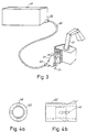
- Fig. 3
- schematically shows a device for applying of the insulating layer being part of the facility of fig. 1;
- Fig. 4a
- and 4b show an ejector, being part of the device of fig. 2, for providing of a unidirectional air stream;
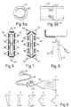
- Fig. 5a
- and 5b show an ejector, being part of the device of fig. 2, for creating a rotating movement of an air stream containing fibres;
- Fig. 6
- is a schematic view taken perpendicular to the outlet of a fibre applying nozzle, being part of the device of fig. 2, showing a preferred arrangement of liquid nozzles;
- Fig. 7
- shows a modified embodiment of the arrangement of fig. 6;
- Fig. 8
- schematically shows, in a top view, the fibre applying and liquid nozzles, respectively, described with reference to figs. 5 and 6; and
- Fig. 9
- schematically shows the distribution of fibres applyed onto an object at different modes of operation with different parameters set which influence on the fibre stream.
- The embodiment to be described refers to the application of a heat insulating layer to the outside of an oven cavity intended to be mounted in a domestic range. Alternatively, the oven cavity may constitute a separate unit in the shape of a built-in oven. Suitably, the application of the insulating layer is carried out in an automatic work station of a suitable design. In Fig. 1 the design of such work station is schematically shown.
- In the embodiment a method is being used according to which fibres of a inorganic heat insulating material are sprayed onto the external surface of the oven cavity under simultaneous wetting of the fibres with an aqueous binder causing the fibres to stick to the cavity. The fibres are glass-wool fibres and the binder is of the silicate type and in the example described the binder is EKA Thorsil®, having 14 percentage by weight of Silicon and 86 percentage by weight of water. After the application of the glass-wool fibres on the outside of the cavity the layer is formed and compressed against surfaces having insignificant adhesiveness, for example having a coating of PTFE. Then, the water contained in the layer has to be removed for the silicate binder to harden. This drying process can take place in a convection oven at temperatures below 600 °C or by means of infrared radiation elements. Finally, an acetate-based binder can be applied to the insulating layer in order to prevent or substantially limit the creation of dust during the handling of the oven cavity and, in addition, to improve the mechanical strenght of the layer. Alternatively, the application can take place prior to drying if the drying temperatures do not exceed about 200 °C. An example of such binder is NATIONAL®, ML 7224 which is to be applied as an aqueous solution.
- The continued description will be concentrated on those parts of the application process concerned with the transfer of fibres from a store to an application nozzle and to the application itself of the fibres to the surface of the oven cavity via said nozzle. However, the subsequent forming and surface treatment of the insulating layer thus applied will not be discussed in detail.
- In Fig. 1 an establishment is shown in which an insulating layer of the kind referred to can be applied to the outside of an oven cavity designated by 10. The establishment is built up around a handling
robot 11 which collects an oven cavity from acollecting station 12 and brings it to awork station 13 where the application is to take place. After the application the robot moves the cavity to anothercollecting station 14 for further transport within the production establishment. - The fibre to be applied to the oven cavity is obtained from a
fibre tearing machine 15 of a kind known per se.Afibre bale 16 is inserted in the machine to be fed by a feeding means 17 towardsrollers hose 20 the outlet end of which opens into anapplication nozzle 21. In the figure there are also shown two ejectors, one of which, designated 22, disposed at the inlet of the hose and another one, designated 23, disposed at the outlet end of the hose. The function of the ejectors will be described more in detail in the following. - The
application nozzle 21 emits a stream of fibres which is directed towards the oven cavity. In order for the fibres to stick to the surface of said cavity the fibres are wetted with liquid fromnozzles 24 disposed around the outlet opening of said nozzle. The liquid is provided from a liquid system comprising acontainer 25 and apump 26. As indicated above, the liquid consists of a slicate binder and water and to prevent sedimentation when the nozzle is not operating the liquid is circulated in the system and, in addition, astirrer 27 is provided in thecontainer 25 which is activated during the circulation process. A pumping device can also be used which continuously adds water. - During the application the
robot 11 is arranged to move the different sides of the cavity past the application nozzle, which is fixed. In doing so, the gripping tool of the robot performs the different movements in synchronism with the way of working of the nozzle so that layers of a predetermined thickness are applied to the sides of the cavity. The application process is controlled by acontrol unit 28 programmed to perform a number of different programs to be selected by akeyboard 29 or the like. Further, the figure contains ahydraulic pump 30 which operates thefibre tearing machine 15 and aunit 31 comprising valves and regulators for air and liquid to theejectors liquid nozzles 24, respectively. - Subsequent to the application the humid loose fibre layer on the sides of the cavity has to be formed or compressed which takes place in a forming
station 32 where forming parts coated with PTFE are brought into contact with said sides. After the forming the insulating layer has to be dryed which, as already mentioned, can take place in a convection oven or by means of infrared radiation elements. Such drying devices have been omitted in Fig. 1. However, aspraying equipment 33 is shown by means of which an additional layer is applyed to the formed and dryed insulating layer. As mentioned above, the purpose of this coating is to prevent dust emission from the insulating layer and in addition the layer is given a higher mechanical strength. - During the application of the insulating layer to the external surfaces of the oven cavity, to a certain extent glass fibres will find their way into said cavity and stick to the interior surfaces of the cavity. To prevent this the gripping tool of the
robot 11 has been designed as shown in Fig. 2. The cavity is held by the gripping tool by twoparts wall 36 which, via anintermediate sealing gasket 37, bears against aflange 38 surrounding the open end of the cavity. By a conduit 39 a gas, suitably air, is introduced into the cavity to create an overpressure which prevents fibres and binder from entering through remaining minor openings for details to be mounted, such as theopening 40 in the rear wall of the cavity. - With reference to Fig. 3 the device for applying the insulating layer to the external sides of the cavity will now be described. Glass fibres are available in a store 41 and, in principle, these fibres can have been delivered in finely divided form. In the embodiment the store is part of the fibre tearing machine shown in Fig. 1 and glass fibres for the machine are delivered in the form of compressed fibre bales. In the way described, the machine operates to tear the fibre bale into small fibre bundles which by means of air are blown into the
conduit 20 to create in this conduit a fibre stream mixed with air. The means for generating said air stream have not been shown in the figure. In order to facilitate the blowing of the fibres into the conduit air jets are introduced in theejector 22 from different sides so that a vacuum is established sucking the fibres into said conduit and so that additional air is introduced into the conduit for the transport of fibres through same. In figures 4a and 4b an embodiment of the ejector is shown in which four bores 42 open in an area of reduced cross-section, said bores being disposed crosswise. The bores extend in the direction of the fibre stream through the ejector but intersect this direction at an angle of about 30 degrees. The number of bores can be increased and in a modified embodiment, not shown, said number has been doubled and the bores have been evenly distributed along the periphery. A number of such modifications can be made within the scope of the idea of invention. - As appears from figures 1 and 3, between the
conduit 20 and theapplication nozzle 21 an additional ejector is provided for the purpose of creating a suitably shaped fibre stream leaving the nozzle. The nozzle has an outlet opening which is mainly rectangular in order that the insulating layer applied be given the shape of a swath of a corresponding rectangular cross-section. Therefore, the object is to distribute the fibre flow evenly along the whole of the outlet opening and, accordingly, theejector 23 is designed so as to apply a rotational movement of sufficient magnitude to the fibre stream in the conduit. In figures 5a and 5b an embodiment is shown in which, as in theejector 22, fourbores 43 open inside the injector in an area of reduced diameter. Here, the bores are directed tangentially to the circular inner wall of the ejector but also at an angle with respect to the direction of the fibre stream through the ejector, said angle, preferably, being at about 45 degrees. As in theejector 22 the number of bores can be varied as well as the disposition of same without departing from the idea of invention. For example, a modified embodiment, not shown, has been tested in which eight bores have beeen evenly distributed along the periphery of the ejector. Theejectors - When, by means of the
ejector 23, the fibre stream from thenozzle 21 has been given a suitable shape another problem arises, namely the problem of wetting in a correct way the outflowing fibres so that they stick to the surface to be coated. To that end a number ofliquid nozzles 24 have been disposed adjacent to the rectangular nozzle opening so that the two rectangular sides of the fibre stream be wetted as evenly as possible. In Fig. 3 two rows of three nozzles each have been arranged vertically along the sides of the nozzle. The jets from the nozzles overlap so that complete coverage is achieved. Modified embodiments are shown in figures 6 and 7. In Fig. 6 fourliquid nozzles application nozzle 21 to form vertical rows whereas at the bottom and at the topliquid nozzles liquid nozzles liquid nozzles nozzles - In order to improve the adhesion of fibre to the surface of the oven cavity it is an advantage if said surface be wetted with the mixture of water and binder prior to being hit by the wetted fibres. In Fig. 8 two
liquid nozzles application nozzle 21. Thenozzle 55 forms with the fibre stream an angle B which is smaller than the corresponding angle for thenozzle 54 resulting in that part of the liquid jet hitting the part of the oven cavity about to be hit by the fibre stream. The angle B is optimized so that wetting of the surface takes place without negatively influencing on the wetting of the fibre stream. As appears from the figure another angle A has been drawn in indicating a certain inclination of the direction of the fibre stream from said nozzle with respect to the normal to the surface of the oven cavity. The purpose of this inclination is to minimize the fibre loss during application. - In connection with the embodiments shown in the drawings it has been shown that a good result is dependent on a number of parameters being optimized correctly. In Fig. 9 another such parameter is shown, namely the inclination of the
conduit 20 vertically at the passage to theejector 23. Tilting of the conduit upwards causes an increase of the amount of fibre at the lower part of the application nozzle whereas tilting of the conduit downwards gives the opposite effect. In the case designated 1 an even coverage of the surface is obtained which can be expected at the optimal setting of the various parameters, such as air quantity and the directions in the ejectors, the inclination of the conduit mentioned, the design of the application nozzle and the positioning of the liquid nozzles and the flow charateristics of same. In case No. 2 an uneven distribution is achieved due to incorrect inclination of the conduit to theejector 23. Here, the conduit is too high, that is the conduit leans downwards towards the ejector. In case No. 3 too small quantity of fibre is present at the centre possibly due to too much air in therotational ejector 23 or insufficient quantity of air in theejector 22. In case No. 4 the fibres are concentrated in the centre, at the top and at the bottom which could be caused by too much air both in therotational ejector 23 and in theejector 22. The case No. 5 gives a concentration of fibres in the centre possibly due to insufficient amount of air to therotational ejector 23. In case No. 6 there is shown the distribution resulting from bothejectors
Claims (14)
- A device for applying an insulation to a surface of an object (10), comprising a store (15) of fibres of an inorganic material, a conduit means (20) for the transfer of fibres from the store (15) to a spray nozzle (21), means for generating an air flow in the conduit means (20) directed towards the nozzle, first ejector means (22) provided at the end of the conduit facing the store (15) for introducing air jets into said conduit means (20) in the direction of the fibre stream, second ejector means (23) disposed at the end of the conduit means facing the spray nozzle (21) for the introduction of air jets directed so as to bring the fibre stream into rotation, and means (24;44-47;48-53) disposed adjacent to the spray nozzle (21) for introducing liquid jets, comprising a mixture of water and a binder, into the fibre stream outside of the spray nozzle, said liquid jets being introduced in the direction of the fibre stream but forming an angle with said stream.
- A device according to claim 1, characterized in that the first ejector means (22) comprise a number of nozzles (42) distributed along the periphery of the conduit means, said nozzles being directed so that the air jets from said nozzles form an angle with the passing fibre stream of about 30 degrees.
- A device according to claim 2, characterized in that eight nozzles (22) are provided which are evenly distributed.
- A device according to claim 1, characterized in that the second ejector means (23) comprise at least four nozzles (43) disposed crosswise and being directed so as to have the jets from said nozzles inciding tangentally in the conduit means (20), forming an angle of about 45 degrees with the passing fibre stream.
- A device according to claim 1, characterized in that the spray nozzle (21) has a cylindrical inlet part and an outlet part which is mainly rectangular where the shorter side is mainly of the same magnitude as the diameter of said inlet part of the nozzle whereas the longer side has a size which is considerably greater.
- A device according to claim 4, characterized in that a number of liquid nozzles (24;44,45;48,49) are disposed in a row along the longer sides of the spray nozzle (21) at both sides of said nozzle.
- A device according to claim 6, characterized in that at at least one of the shorter sides of the spray nozzle (21) there is provided at least one liquid nozzle (46,47;50-53).
- A device according to claim 6, characterized in that at least one liquid nozzle (46,47;50-53) is provided at each of the shorter sides.
- A device according to any of claims 5-8, characterized in that means (11) are provided to move the surface of the object (10) past the spray nozzle (21) which is directed so that the fibre stream from said nozzle hits the surface (10) at an angle to the direction of movement of said object which is slightly greater than 90°.
- A device according to claim 7, characterized in that the liquid nozzles (55) in the forward row, as seen in the direction of movement of said object (10), are directed so that the liquid jets from said nozzles are wetting also the surface of said object prior to the application of the fibres.
- A device according to claim 1, characterized in that the binder is of the silicate-based type.
- A device according to claim 4, characterized in that the conduit means (20) is connected to the spray nozzle (21) such that the outlet direction of the fibre stream can be set within a range limited by the shorter sides of the outlet opening of the nozzle.
- A device according to any of the preceding claims, characterized in that it comprises means for forming of the wetted fibre layer applied to the object (10) and means for the subsequent drying of said layer.
- A device according to any of claims 1-13, characterized in that it is used in producing an oven provided with a surrounding heat insulation comprising fibres of an inorganic material, preferably of the type glass fibres or mineral fibres.
Applications Claiming Priority (3)
| Application Number | Priority Date | Filing Date | Title |
|---|---|---|---|
| SE9102067 | 1991-07-02 | ||
| SE9102067A SE468722B (en) | 1991-07-02 | 1991-07-02 | DEVICE FOR APPLICATION OF AN INSULATION CONTAINING FIBERS ON A SURFACE, INCLUDING AN BODY FOR CREATING AN AIR CIRCUM THAT BRINGS THE FIBER CIRCUM IN ROTATION |
| PCT/SE1992/000466 WO1993001444A1 (en) | 1991-07-02 | 1992-06-24 | A method and a device for applying of an insulating layer on a surface of an object |
Publications (3)
| Publication Number | Publication Date |
|---|---|
| EP0550721A1 EP0550721A1 (en) | 1993-07-14 |
| EP0550721B1 EP0550721B1 (en) | 1994-12-28 |
| EP0550721B2 true EP0550721B2 (en) | 1997-07-23 |
Family
ID=20383237
Family Applications (1)
| Application Number | Title | Priority Date | Filing Date |
|---|---|---|---|
| EP92915255A Expired - Lifetime EP0550721B2 (en) | 1991-07-02 | 1992-06-24 | Device for applying an insulating layer onto the surface of an object |
Country Status (8)
| Country | Link |
|---|---|
| US (1) | US5507869A (en) |
| EP (1) | EP0550721B2 (en) |
| AT (1) | ATE116417T1 (en) |
| CA (1) | CA2090871A1 (en) |
| DE (1) | DE69201051T3 (en) |
| DK (1) | DK0550721T3 (en) |
| SE (1) | SE468722B (en) |
| WO (1) | WO1993001444A1 (en) |
Families Citing this family (14)
| Publication number | Priority date | Publication date | Assignee | Title |
|---|---|---|---|---|
| DE29521023U1 (en) * | 1995-05-08 | 1996-08-01 | Krauss-Maffei AG, 80997 München | Reaction casting machine |
| DE19633947A1 (en) * | 1996-08-22 | 1998-02-26 | Bayerische Motoren Werke Ag | Attachment, in particular for motor vehicle interiors |
| US5947646A (en) * | 1997-02-25 | 1999-09-07 | Guardian Fiberglass, Inc. | System for blowing loose-fill insulation |
| US6261679B1 (en) | 1998-05-22 | 2001-07-17 | Kimberly-Clark Worldwide, Inc. | Fibrous absorbent material and methods of making the same |
| DE19848874A1 (en) * | 1998-10-22 | 2000-04-27 | Bsh Bosch Siemens Hausgeraete | oven |
| FR2801243B1 (en) | 1999-11-18 | 2006-06-02 | Saint Gobain Isover | METHOD FOR APPLYING AN INSULATING LAYER ON A SURFACE OF AN OBJECT AND CORRESPONDING ISO PRODUCT |
| DE10211331B4 (en) * | 2002-03-14 | 2006-02-02 | Sto Ag | Method for producing an airgel-containing insulating layer on an outer wall of a building |
| AU2005223454A1 (en) * | 2004-03-18 | 2005-09-29 | Johns Manville | System and method for forming an insulation particle/air suspension |
| ITTO20120812A1 (en) * | 2012-09-18 | 2014-03-19 | Indesit Co Spa | METHOD TO INSERT AN OVEN FLASK FOR COOKING FOOD |
| FR3054636B1 (en) | 2016-08-01 | 2019-01-25 | Saint-Gobain Isover | INSULATION METHOD AND APPARATUS OBTAINED |
| CN110983632A (en) * | 2019-12-31 | 2020-04-10 | 重庆再升科技股份有限公司 | Cotton collecting cover |
| CN111074425A (en) * | 2019-12-31 | 2020-04-28 | 重庆再升科技股份有限公司 | Preparation method of high-drainage sound-insulation heat-insulation glass fiber cotton felt and product |
| CN111058186A (en) * | 2019-12-31 | 2020-04-24 | 重庆再升科技股份有限公司 | Preparation method of high-strength sound-proof heat-insulation glass fiber cotton felt and product |
| US20250239586A1 (en) * | 2024-01-18 | 2025-07-24 | Durr Systems, Inc. | Apparatus And Method For Inductive Heating Of Coated Web Substrates During Process Operations |
Family Cites Families (21)
| Publication number | Priority date | Publication date | Assignee | Title |
|---|---|---|---|---|
| US1702043A (en) * | 1923-09-15 | 1929-02-12 | Turner Tanning Machinery Co | Method and apparatus for applying and treating varnish |
| US1718507A (en) * | 1923-12-17 | 1929-06-25 | Wenzel | Heat insulation of walls |
| US2578412A (en) * | 1950-01-10 | 1951-12-11 | Emery J Fisher | Spray gun for comminuted material and adhesive |
| US3871583A (en) * | 1969-12-29 | 1975-03-18 | Paul H Kellert | Cement spray gun with remote air injection |
| FR2314775A1 (en) * | 1975-06-18 | 1977-01-14 | Inst Francais Du Petrole | APPARATUS FOR FORMING A LAYER OF A PULVERULENT PRODUCT ON THE SURFACE OF AN OBJECT |
| DE2719439C2 (en) * | 1977-04-30 | 1984-01-19 | Messerschmitt-Bölkow-Blohm GmbH, 8000 München | Pivoting nozzle for vector control |
| DE2815616C2 (en) * | 1978-04-11 | 1982-11-18 | Woellner-Werke, 6700 Ludwigshafen | Process for the spray insulation of metallic and / or non-metallic objects with mineral fibers and a binding agent |
| IT1122846B (en) * | 1978-09-25 | 1986-04-23 | Woellner Werke | PROCEDURE FOR SPRAY INSULATING METALLIC AND / OR NON-METALLIC OBJECTS |
| CA1190035A (en) * | 1982-01-06 | 1985-07-09 | Daniel D. O'connell | Sprayable acoustical composition |
| US4504602A (en) * | 1982-01-06 | 1985-03-12 | United States Gypsum Company | Sprayable acoustical composition |
| FR2535246A1 (en) * | 1982-10-29 | 1984-05-04 | Saint Gobain Isover | ROOF SEALING INSULATION PANELS, METHOD AND DEVICES FOR THEIR MANUFACTURE |
| US4542040A (en) * | 1982-12-13 | 1985-09-17 | Nowak David M | Method and means for spraying aggregates for fireproof insulation onto a substratum |
| JPS59205480A (en) * | 1983-05-09 | 1984-11-21 | Usui Internatl Ind Co Ltd | Method for reinforcing ceramic plasma spraying coating layer for heat insulating engine parts |
| US4673594A (en) * | 1984-10-12 | 1987-06-16 | Manville Service Corporation | Method for applying a layer of fiber on a surface and a refractory material produced thereby |
| JPS61111973A (en) * | 1984-10-31 | 1986-05-30 | 黒崎窯業株式会社 | Spray method for refractory spray material |
| EP0222563A1 (en) * | 1985-11-02 | 1987-05-20 | MB GROUP plc | The coating of articles |
| US4814201A (en) * | 1987-08-31 | 1989-03-21 | Smith William H | Apparatus and method for applying a layer of fiber on a surface |
| US4968556A (en) * | 1988-03-25 | 1990-11-06 | The Reynolds Company | Coating for fiberglass insulation |
| US4852392A (en) * | 1988-08-12 | 1989-08-01 | Evans Robert G | High pressure drum testing apparatus and method |
| FR2640546B1 (en) * | 1988-12-21 | 1991-04-12 | Saint Gobain Isover | PROCESS FOR OBTAINING A SURFACE INSULATION PANEL BASED ON MINERAL FIBERS |
| US5064689A (en) * | 1989-03-20 | 1991-11-12 | Weyerhaeuser Company | Method of treating discontinuous fibers |
-
1991
- 1991-07-02 SE SE9102067A patent/SE468722B/en not_active IP Right Cessation
-
1992
- 1992-06-24 AT AT92915255T patent/ATE116417T1/en not_active IP Right Cessation
- 1992-06-24 DE DE69201051T patent/DE69201051T3/en not_active Expired - Fee Related
- 1992-06-24 CA CA002090871A patent/CA2090871A1/en not_active Abandoned
- 1992-06-24 EP EP92915255A patent/EP0550721B2/en not_active Expired - Lifetime
- 1992-06-24 DK DK92915255.1T patent/DK0550721T3/en active
- 1992-06-24 WO PCT/SE1992/000466 patent/WO1993001444A1/en not_active Ceased
- 1992-06-24 US US07/980,801 patent/US5507869A/en not_active Expired - Fee Related
Also Published As
| Publication number | Publication date |
|---|---|
| DE69201051D1 (en) | 1995-02-09 |
| SE9102067D0 (en) | 1991-07-02 |
| DK0550721T3 (en) | 1995-05-29 |
| EP0550721B1 (en) | 1994-12-28 |
| EP0550721A1 (en) | 1993-07-14 |
| US5507869A (en) | 1996-04-16 |
| SE9102067L (en) | 1993-01-03 |
| DE69201051T3 (en) | 1998-03-05 |
| SE468722B (en) | 1993-03-08 |
| WO1993001444A1 (en) | 1993-01-21 |
| DE69201051T2 (en) | 1995-05-18 |
| CA2090871A1 (en) | 1993-01-03 |
| ATE116417T1 (en) | 1995-01-15 |
Similar Documents
| Publication | Publication Date | Title |
|---|---|---|
| EP0550721B1 (en) | Device for applying an insulating layer onto the surface of an object | |
| US3311085A (en) | Apparatus for coating objects | |
| JPS5876562A (en) | Method and apparatus for improving distribution in element for receiving fiber carried by gas stream | |
| CA1106580A (en) | Spray method of refractory material | |
| WO2008085461A1 (en) | Improved cooling ring for use in manufacture of fiberglass wool | |
| AU732714B2 (en) | Method for coating fibers with glue | |
| EP0329118A2 (en) | Method and apparatus for producing desired fiber column configuration | |
| EP1204610A1 (en) | System for preparing polymer encapsulated glass fiber pellets | |
| CN113953131B (en) | Spraying method for aircraft parts | |
| CZ160393A3 (en) | Process of forming a preformed product, and apparatus for making the same | |
| EP1042243A1 (en) | Method and apparatus for integrating organic fibers with mineral fibers | |
| US3343933A (en) | Binder distribution method for producing mineral wool board | |
| EP0142715B1 (en) | Insulation system | |
| MXPA02001062A (en) | Method and apparatus for sealing capsules and capsules suitable for use in said method and apparatus. | |
| CA1135177A (en) | Device for cutting and shooting fibres with stabilised orientation | |
| US20210323010A1 (en) | Facility for producing glass wool and system for spraying products onto fibers of such a facility | |
| CN218796844U (en) | Battery steel casing inner wall graphite spraying device | |
| US4923731A (en) | Novel preform screens and preform product | |
| JPH0231170Y2 (en) | ||
| JP7823716B2 (en) | Spray nozzle and spray application system | |
| KR102753275B1 (en) | Container internal coating system that facilitates internal coating | |
| EP0611844B1 (en) | Apparatus for steaming a material in a silo | |
| CN212820738U (en) | Spraying device for valve ball | |
| JPH04232702A (en) | Fiber-contained material overlaid with new fiber | |
| CN209348135U (en) | A kind of safeguard structure of spray dryer |
Legal Events
| Date | Code | Title | Description |
|---|---|---|---|
| PUAI | Public reference made under article 153(3) epc to a published international application that has entered the european phase |
Free format text: ORIGINAL CODE: 0009012 |
|
| 17P | Request for examination filed |
Effective date: 19930311 |
|
| AK | Designated contracting states |
Kind code of ref document: A1 Designated state(s): AT CH DE DK FR GB IT LI NL |
|
| 17Q | First examination report despatched |
Effective date: 19931008 |
|
| GRAA | (expected) grant |
Free format text: ORIGINAL CODE: 0009210 |
|
| REF | Corresponds to: |
Ref document number: 116417 Country of ref document: AT Date of ref document: 19950115 Kind code of ref document: T |
|
| REF | Corresponds to: |
Ref document number: 69201051 Country of ref document: DE Date of ref document: 19950209 |
|
| ITF | It: translation for a ep patent filed | ||
| ET | Fr: translation filed | ||
| REG | Reference to a national code |
Ref country code: DK Ref legal event code: T3 |
|
| PLBI | Opposition filed |
Free format text: ORIGINAL CODE: 0009260 |
|
| 26 | Opposition filed |
Opponent name: ROCKWOOL INTERNATIONAL A/S Effective date: 19950927 |
|
| NLR1 | Nl: opposition has been filed with the epo |
Opponent name: ROCKWOOL INTERNATIONAL A/S |
|
| PLBF | Reply of patent proprietor to notice(s) of opposition |
Free format text: ORIGINAL CODE: EPIDOS OBSO |
|
| PLAW | Interlocutory decision in opposition |
Free format text: ORIGINAL CODE: EPIDOS IDOP |
|
| PLAW | Interlocutory decision in opposition |
Free format text: ORIGINAL CODE: EPIDOS IDOP |
|
| PUAH | Patent maintained in amended form |
Free format text: ORIGINAL CODE: 0009272 |
|
| STAA | Information on the status of an ep patent application or granted ep patent |
Free format text: STATUS: PATENT MAINTAINED AS AMENDED |
|
| 27A | Patent maintained in amended form |
Effective date: 19970723 |
|
| AK | Designated contracting states |
Kind code of ref document: B2 Designated state(s): AT CH DE DK FR GB IT LI NL |
|
| REG | Reference to a national code |
Ref country code: CH Ref legal event code: AEN Free format text: AUFRECHTERHALTUNG DES PATENTES IN GEAENDERTER FORM |
|
| NLR2 | Nl: decision of opposition | ||
| ITF | It: translation for a ep patent filed | ||
| ET3 | Fr: translation filed ** decision concerning opposition | ||
| NLR3 | Nl: receipt of modified translations in the netherlands language after an opposition procedure | ||
| REG | Reference to a national code |
Ref country code: DK Ref legal event code: T4 |
|
| PGFP | Annual fee paid to national office [announced via postgrant information from national office to epo] |
Ref country code: FR Payment date: 19980609 Year of fee payment: 7 |
|
| PGFP | Annual fee paid to national office [announced via postgrant information from national office to epo] |
Ref country code: DK Payment date: 19980612 Year of fee payment: 7 |
|
| PGFP | Annual fee paid to national office [announced via postgrant information from national office to epo] |
Ref country code: AT Payment date: 19980615 Year of fee payment: 7 Ref country code: GB Payment date: 19980615 Year of fee payment: 7 |
|
| PGFP | Annual fee paid to national office [announced via postgrant information from national office to epo] |
Ref country code: NL Payment date: 19980629 Year of fee payment: 7 |
|
| PGFP | Annual fee paid to national office [announced via postgrant information from national office to epo] |
Ref country code: DE Payment date: 19980706 Year of fee payment: 7 |
|
| PGFP | Annual fee paid to national office [announced via postgrant information from national office to epo] |
Ref country code: CH Payment date: 19980708 Year of fee payment: 7 |
|
| PG25 | Lapsed in a contracting state [announced via postgrant information from national office to epo] |
Ref country code: GB Free format text: LAPSE BECAUSE OF NON-PAYMENT OF DUE FEES Effective date: 19990624 Ref country code: AT Free format text: LAPSE BECAUSE OF NON-PAYMENT OF DUE FEES Effective date: 19990624 |
|
| PG25 | Lapsed in a contracting state [announced via postgrant information from national office to epo] |
Ref country code: LI Free format text: LAPSE BECAUSE OF NON-PAYMENT OF DUE FEES Effective date: 19990630 Ref country code: FR Free format text: THE PATENT HAS BEEN ANNULLED BY A DECISION OF A NATIONAL AUTHORITY Effective date: 19990630 Ref country code: DK Free format text: LAPSE BECAUSE OF NON-PAYMENT OF DUE FEES Effective date: 19990630 Ref country code: CH Free format text: LAPSE BECAUSE OF NON-PAYMENT OF DUE FEES Effective date: 19990630 |
|
| PG25 | Lapsed in a contracting state [announced via postgrant information from national office to epo] |
Ref country code: NL Free format text: LAPSE BECAUSE OF NON-PAYMENT OF DUE FEES Effective date: 20000101 |
|
| REG | Reference to a national code |
Ref country code: CH Ref legal event code: PL |
|
| GBPC | Gb: european patent ceased through non-payment of renewal fee |
Effective date: 19990624 |
|
| NLV4 | Nl: lapsed or anulled due to non-payment of the annual fee |
Effective date: 20000101 |
|
| REG | Reference to a national code |
Ref country code: DK Ref legal event code: EBP |
|
| PG25 | Lapsed in a contracting state [announced via postgrant information from national office to epo] |
Ref country code: DE Free format text: LAPSE BECAUSE OF NON-PAYMENT OF DUE FEES Effective date: 20000503 |
|
| REG | Reference to a national code |
Ref country code: FR Ref legal event code: ST |
|
| PG25 | Lapsed in a contracting state [announced via postgrant information from national office to epo] |
Ref country code: IT Free format text: LAPSE BECAUSE OF NON-PAYMENT OF DUE FEES;WARNING: LAPSES OF ITALIAN PATENTS WITH EFFECTIVE DATE BEFORE 2007 MAY HAVE OCCURRED AT ANY TIME BEFORE 2007. THE CORRECT EFFECTIVE DATE MAY BE DIFFERENT FROM THE ONE RECORDED. Effective date: 20050624 |