EP0550700B1 - Combustion system for reduction of nitrogen oxides - Google Patents
Combustion system for reduction of nitrogen oxides Download PDFInfo
- Publication number
- EP0550700B1 EP0550700B1 EP92902517A EP92902517A EP0550700B1 EP 0550700 B1 EP0550700 B1 EP 0550700B1 EP 92902517 A EP92902517 A EP 92902517A EP 92902517 A EP92902517 A EP 92902517A EP 0550700 B1 EP0550700 B1 EP 0550700B1
- Authority
- EP
- European Patent Office
- Prior art keywords
- flow
- fuel
- concentric
- burner
- swirl
- Prior art date
- Legal status (The legal status is an assumption and is not a legal conclusion. Google has not performed a legal analysis and makes no representation as to the accuracy of the status listed.)
- Expired - Lifetime
Links
- 238000002485 combustion reaction Methods 0.000 title claims abstract description 80
- 230000009467 reduction Effects 0.000 title description 17
- MWUXSHHQAYIFBG-UHFFFAOYSA-N nitrogen oxide Inorganic materials O=[N] MWUXSHHQAYIFBG-UHFFFAOYSA-N 0.000 title description 9
- 239000000446 fuel Substances 0.000 claims abstract description 213
- 238000002156 mixing Methods 0.000 claims abstract description 55
- 238000013517 stratification Methods 0.000 claims abstract description 23
- 239000007789 gas Substances 0.000 claims description 49
- UGFAIRIUMAVXCW-UHFFFAOYSA-N Carbon monoxide Chemical compound [O+]#[C-] UGFAIRIUMAVXCW-UHFFFAOYSA-N 0.000 claims description 45
- 239000003546 flue gas Substances 0.000 claims description 45
- 238000000034 method Methods 0.000 claims description 32
- 238000003780 insertion Methods 0.000 claims description 31
- 230000037431 insertion Effects 0.000 claims description 31
- 230000001590 oxidative effect Effects 0.000 claims description 23
- 239000007800 oxidant agent Substances 0.000 claims description 22
- 230000001965 increasing effect Effects 0.000 claims description 18
- 230000015572 biosynthetic process Effects 0.000 claims description 15
- 239000003245 coal Substances 0.000 claims description 14
- 230000003134 recirculating effect Effects 0.000 claims description 8
- 239000000295 fuel oil Substances 0.000 claims description 6
- 150000002430 hydrocarbons Chemical class 0.000 claims description 5
- 230000000670 limiting effect Effects 0.000 claims description 5
- 229930195733 hydrocarbon Natural products 0.000 claims description 4
- 238000011144 upstream manufacturing Methods 0.000 claims description 4
- 239000010742 number 1 fuel oil Substances 0.000 claims description 3
- 230000000977 initiatory effect Effects 0.000 claims description 2
- 239000004215 Carbon black (E152) Substances 0.000 claims 3
- 230000000694 effects Effects 0.000 abstract description 27
- 239000000203 mixture Substances 0.000 abstract description 11
- 239000012530 fluid Substances 0.000 abstract description 8
- 239000007788 liquid Substances 0.000 abstract description 3
- 239000004449 solid propellant Substances 0.000 abstract description 2
- VNWKTOKETHGBQD-UHFFFAOYSA-N methane Chemical compound C VNWKTOKETHGBQD-UHFFFAOYSA-N 0.000 description 31
- IJGRMHOSHXDMSA-UHFFFAOYSA-N Atomic nitrogen Chemical compound N#N IJGRMHOSHXDMSA-UHFFFAOYSA-N 0.000 description 22
- 238000009826 distribution Methods 0.000 description 17
- QVGXLLKOCUKJST-UHFFFAOYSA-N atomic oxygen Chemical compound [O] QVGXLLKOCUKJST-UHFFFAOYSA-N 0.000 description 16
- 229910052760 oxygen Inorganic materials 0.000 description 16
- 239000001301 oxygen Substances 0.000 description 16
- 238000002347 injection Methods 0.000 description 12
- 239000007924 injection Substances 0.000 description 12
- 239000003345 natural gas Substances 0.000 description 12
- 229910052757 nitrogen Inorganic materials 0.000 description 11
- 238000013461 design Methods 0.000 description 8
- 230000002349 favourable effect Effects 0.000 description 7
- 239000002737 fuel gas Substances 0.000 description 7
- 239000003921 oil Substances 0.000 description 7
- XLYOFNOQVPJJNP-UHFFFAOYSA-N water Substances O XLYOFNOQVPJJNP-UHFFFAOYSA-N 0.000 description 7
- 238000012512 characterization method Methods 0.000 description 6
- 238000004519 manufacturing process Methods 0.000 description 6
- 238000005259 measurement Methods 0.000 description 6
- 238000002474 experimental method Methods 0.000 description 5
- 230000002829 reductive effect Effects 0.000 description 5
- 238000006243 chemical reaction Methods 0.000 description 3
- 239000010763 heavy fuel oil Substances 0.000 description 3
- 230000008569 process Effects 0.000 description 3
- 238000000197 pyrolysis Methods 0.000 description 3
- 238000011160 research Methods 0.000 description 3
- 239000002002 slurry Substances 0.000 description 3
- OKTJSMMVPCPJKN-UHFFFAOYSA-N Carbon Chemical compound [C] OKTJSMMVPCPJKN-UHFFFAOYSA-N 0.000 description 2
- QAOWNCQODCNURD-UHFFFAOYSA-N Sulfuric acid Chemical compound OS(O)(=O)=O QAOWNCQODCNURD-UHFFFAOYSA-N 0.000 description 2
- 230000008901 benefit Effects 0.000 description 2
- 229910052799 carbon Inorganic materials 0.000 description 2
- 238000013016 damping Methods 0.000 description 2
- 230000007423 decrease Effects 0.000 description 2
- 230000001419 dependent effect Effects 0.000 description 2
- 238000010790 dilution Methods 0.000 description 2
- 239000012895 dilution Substances 0.000 description 2
- 238000006073 displacement reaction Methods 0.000 description 2
- 238000000605 extraction Methods 0.000 description 2
- 230000003993 interaction Effects 0.000 description 2
- 239000010747 number 6 fuel oil Substances 0.000 description 2
- 230000003647 oxidation Effects 0.000 description 2
- 238000007254 oxidation reaction Methods 0.000 description 2
- 230000002028 premature Effects 0.000 description 2
- 239000000523 sample Substances 0.000 description 2
- 239000007787 solid Substances 0.000 description 2
- 229910001220 stainless steel Inorganic materials 0.000 description 2
- 239000010935 stainless steel Substances 0.000 description 2
- MYMOFIZGZYHOMD-UHFFFAOYSA-N Dioxygen Chemical compound O=O MYMOFIZGZYHOMD-UHFFFAOYSA-N 0.000 description 1
- 230000006978 adaptation Effects 0.000 description 1
- 238000005273 aeration Methods 0.000 description 1
- 230000004888 barrier function Effects 0.000 description 1
- 235000013405 beer Nutrition 0.000 description 1
- 230000033228 biological regulation Effects 0.000 description 1
- 230000015556 catabolic process Effects 0.000 description 1
- 239000013626 chemical specie Substances 0.000 description 1
- 239000000567 combustion gas Substances 0.000 description 1
- 238000005094 computer simulation Methods 0.000 description 1
- 238000012937 correction Methods 0.000 description 1
- 230000006378 damage Effects 0.000 description 1
- 230000003247 decreasing effect Effects 0.000 description 1
- 230000000779 depleting effect Effects 0.000 description 1
- 230000000994 depressogenic effect Effects 0.000 description 1
- 230000002542 deteriorative effect Effects 0.000 description 1
- 238000011161 development Methods 0.000 description 1
- 230000003467 diminishing effect Effects 0.000 description 1
- 229910001882 dioxygen Inorganic materials 0.000 description 1
- -1 e.g. Substances 0.000 description 1
- 238000001983 electron spin resonance imaging Methods 0.000 description 1
- 238000005516 engineering process Methods 0.000 description 1
- 230000002708 enhancing effect Effects 0.000 description 1
- 230000007613 environmental effect Effects 0.000 description 1
- 239000002803 fossil fuel Substances 0.000 description 1
- 238000009689 gas atomisation Methods 0.000 description 1
- 230000002401 inhibitory effect Effects 0.000 description 1
- 238000002955 isolation Methods 0.000 description 1
- 238000013507 mapping Methods 0.000 description 1
- 230000007246 mechanism Effects 0.000 description 1
- 238000012986 modification Methods 0.000 description 1
- 230000004048 modification Effects 0.000 description 1
- 238000001745 non-dispersive infrared spectroscopy Methods 0.000 description 1
- 239000010743 number 2 fuel oil Substances 0.000 description 1
- 230000003287 optical effect Effects 0.000 description 1
- 238000005457 optimization Methods 0.000 description 1
- 238000013021 overheating Methods 0.000 description 1
- 230000005298 paramagnetic effect Effects 0.000 description 1
- 238000005086 pumping Methods 0.000 description 1
- 230000005855 radiation Effects 0.000 description 1
- 239000011819 refractory material Substances 0.000 description 1
- 238000000926 separation method Methods 0.000 description 1
- 238000004088 simulation Methods 0.000 description 1
- 239000007921 spray Substances 0.000 description 1
- 229910052717 sulfur Inorganic materials 0.000 description 1
- 230000001629 suppression Effects 0.000 description 1
- 238000003786 synthesis reaction Methods 0.000 description 1
- 238000012360 testing method Methods 0.000 description 1
- 230000009466 transformation Effects 0.000 description 1
- 239000002912 waste gas Substances 0.000 description 1
Images






Classifications
-
- F—MECHANICAL ENGINEERING; LIGHTING; HEATING; WEAPONS; BLASTING
- F23—COMBUSTION APPARATUS; COMBUSTION PROCESSES
- F23C—METHODS OR APPARATUS FOR COMBUSTION USING FLUID FUEL OR SOLID FUEL SUSPENDED IN A CARRIER GAS OR AIR
- F23C7/00—Combustion apparatus characterised by arrangements for air supply
- F23C7/002—Combustion apparatus characterised by arrangements for air supply the air being submitted to a rotary or spinning motion
- F23C7/004—Combustion apparatus characterised by arrangements for air supply the air being submitted to a rotary or spinning motion using vanes
- F23C7/006—Combustion apparatus characterised by arrangements for air supply the air being submitted to a rotary or spinning motion using vanes adjustable
-
- F—MECHANICAL ENGINEERING; LIGHTING; HEATING; WEAPONS; BLASTING
- F23—COMBUSTION APPARATUS; COMBUSTION PROCESSES
- F23C—METHODS OR APPARATUS FOR COMBUSTION USING FLUID FUEL OR SOLID FUEL SUSPENDED IN A CARRIER GAS OR AIR
- F23C9/00—Combustion apparatus characterised by arrangements for returning combustion products or flue gases to the combustion chamber
-
- F—MECHANICAL ENGINEERING; LIGHTING; HEATING; WEAPONS; BLASTING
- F23—COMBUSTION APPARATUS; COMBUSTION PROCESSES
- F23C—METHODS OR APPARATUS FOR COMBUSTION USING FLUID FUEL OR SOLID FUEL SUSPENDED IN A CARRIER GAS OR AIR
- F23C2201/00—Staged combustion
- F23C2201/20—Burner staging
-
- F—MECHANICAL ENGINEERING; LIGHTING; HEATING; WEAPONS; BLASTING
- F23—COMBUSTION APPARATUS; COMBUSTION PROCESSES
- F23C—METHODS OR APPARATUS FOR COMBUSTION USING FLUID FUEL OR SOLID FUEL SUSPENDED IN A CARRIER GAS OR AIR
- F23C2202/00—Fluegas recirculation
- F23C2202/20—Premixing fluegas with fuel
-
- F—MECHANICAL ENGINEERING; LIGHTING; HEATING; WEAPONS; BLASTING
- F23—COMBUSTION APPARATUS; COMBUSTION PROCESSES
- F23C—METHODS OR APPARATUS FOR COMBUSTION USING FLUID FUEL OR SOLID FUEL SUSPENDED IN A CARRIER GAS OR AIR
- F23C2202/00—Fluegas recirculation
- F23C2202/30—Premixing fluegas with combustion air
-
- F—MECHANICAL ENGINEERING; LIGHTING; HEATING; WEAPONS; BLASTING
- F23—COMBUSTION APPARATUS; COMBUSTION PROCESSES
- F23C—METHODS OR APPARATUS FOR COMBUSTION USING FLUID FUEL OR SOLID FUEL SUSPENDED IN A CARRIER GAS OR AIR
- F23C2900/00—Special features of, or arrangements for combustion apparatus using fluid fuels or solid fuels suspended in air; Combustion processes therefor
- F23C2900/06043—Burner staging, i.e. radially stratified flame core burners
Definitions
- This invention relates to the reduction of nitrogen oxide emissions in combustion processes.
- Fuel-rich and -lean combustion zones in flames are created by "staging" the input of either air (overfire air) or fuel with injections positioned at selected axial points along the combustion stream.
- US-A-4,718,359 describes a single stage burner for combustion of fuels, but does not describe low No x burning of a fuel nor stratification to limit mixing of oxidant gases with the fuel flow to maintain a high temperature fuel rich core zone near the burner and to induce mixing of the oxidant gases in a lower temperature recirculation zone spaced from the insertion region.
- the invention also provides a burner system for low NO x -emission burning of fuels, comprising:
- An object of the invention is to reduce the emission of NO x in the combustion of various fuels including natural gas, as well as those having bound nitrogen such as fuel oil and coal.
- the system is particularly useful in utility burners typically employing low excess air levels, e.g., less than about 25% excess air.
- the reduction of NO x is achieved by the application of a fluid dynamic principle of combustion staging by radial stratification to prevent premature mixing of fuel and air.
- radial flame stratification is brought about by a combination of swirling burner air flow and a strong radial density gradient in the flame near the burner.
- Flow stratification has been demonstrated using various mechanical apparatus positioned about a flame for free burning fires and for a turbulent methane jet flame (see Emmons and Ying, Eleventh Symposium on Combustion, pp 475-88, The Combustion Institute (1967) and Beer et al. Combustion and Flame, 1971, 16, 39-43, respectively).
- stratification as used herein is defined as the suppression of mixing of the fluid mass in a core region, typically the fuel-rich flame core in a burner application, with the surrounding fluid positioned around the core, typically air or recycled flue gas, by relative rotation of the air masses about the axis of the core, corresponding to the axis of the burner.
- Ri* is the ratio of the rate of work required for transferring mass in a centrifugal force field with a radial density gradient, and the rate of work that goes into the production of turbulence. As used in the invention, stratification occurs at Richardson numbers above 0.04.
- the flow and mixing pattern achieved with the invention consists of a fuel rich flame zone in the central region of the flame in which high temperature pyrolysis reactions can take place.
- This flame core is preserved by the radial stratification from premature mixing with the rest of the combustion air introduced around the fuel rich flame core.
- the stratification prevents substantial mixing in the regions of the flame having a temperature of about 1700 k or greater.
- the residual fuel is then burned in cooler, highly turbulent flame zones positioned either downstream of the stratified pyrolysis zones or around it in a toroidal vortex (e.g., Fig. 2).
- the radially stratified flame core produces a highly stable flame which has the advantage that the flame tolerates significant depletion of the O 2 concentration in the combustion air - brought about by the admixing of flue gas, without the risk of losing flame.
- the increase in stability results in an increase in the blow-off limits as a consequence of increasing rate of rotation of the airflow.
- Schlieren photographs of a free, initially turbulent methane jet burning in air show that the rotation of the air around the jet laminarizes the flow, with the effect of reducing jet entrainment and hence producing a lengthened fuel rich flame core.
- the reduction of fuel/air mixing within the flame core serves to increase the residence time in the hot fuel rich (oxygen depleted) pyrolysis region of the core which reduces the synthesis of NO x in the stratified zone.
- the improved flame stability brought about by stratification increases the tolerance for the use of oxygen depleted combustion air (by e.g., recirculation of flue gas).
- the final fuel burn-out occurs further downstream of the burner where an internal recirculation zone develops due to vortex breakdown in the swirling flow under low oxygen conditions that also inhibit NO x production.
- an aspect of the invention is that, with stratification as taught herein, a stable flame may be produced with a highly fuel rich region near the core substantially isolated from the surrounding oxidant. Further isolation from the oxidant is achieved by recirculation of low oxygen gas from the effluent.
- the burner is an internal stage system with a single insertion region, i.e., all gas and fuel flows are introduced to the combustion chamber from a single position upstream of combustion.
- the burner consists of a burner face with a central fuel gun surrounded by three annular air nozzles. Both the distribution of the air flow and degree of air swirl are controlled independently in the three annuli to optimize stratification.
- the degree of air swirl is characterized by the swirl number which is the normalized ratio of the angular and linear momenta of the flow.
- the highly flexible burner permits the variation of fuel mixing history, both radially and axially, over wide ranges.
- the system enables, for example, NO x reduction of about 88% (e.g.
- the invention features method and apparatus for reducing NO x emissions from combustion of fuels.
- a single stage burner is provided having a fuel gun arranged-on a burner axis, a first concentric nondivergent nozzle, second concentric nondivergent nozzle and third concentric nondivergent nozzle. Each successive nozzle is arranged at increasing radii from said axis.
- a combustible mixture is flowed through said fuel gun to form a combustible core flow of said mixture along said axis and first, second and third successively concentric flows of gas are provided through said first, second and third concentric nozzles.
- the core flow is combusted in a combustion chamber and said concentric flows and said core flow are stratified by separately controlling the tangential swirl of said concentric flows to form a Rankine vortex.
- the first concentric flow has a swirl equal to or more than said core flow
- second concentric flow has a swirl equal to or less than the swirl of said first concentric flow
- said third concentric flow has a swirl equal or less than said second concentric flow.
- the concentric and core flows are stratified to have a Richardson number of about 0.04 or greater to induce a region in which turbulence is damped in said core.
- the primary gas flow is about 10 to 30% of the total concentric flow with a swirl number of about 0.6 or greater, the secondary gas flow of about 10 to 30% of the total concentric flow with a swirl number of about 0.6 or greater, and the tertiary gas flow of about 40 to 80% of the total concentric flow with a swirl number in the range of about 1.5 or less.
- Flue gas from said combustion is recirculated by providing said flue gas to said concentric nozzles.
- the flue gas is recirculated through said concentric nozzles.
- Steam is provided to said core flow.
- the steam is about 25% or less of said core flow.
- the stratifying is controlled to limit substantial mixing of said concentric and core flows in the regions of said core flow having a temperature of about 1700 K or greater.
- the flows are controlled to induce mixing of said concentric and core flows downstream of stratified region of said core flow having a temperature of about 1700 K or greater.
- the fuel is selected from gaseous fuels, coal and fuel oils.
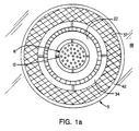
- a burner system 2 in a preferred embodiment is capable of 1.5 mega-watt (about 5 million BTU per hour) output and includes a burner face 3 with three annular nozzle members 22, 34, 42 formed from concentric tubing for supply of combustion air and/or flue effluent flows about a fuel gun 12 positioned on the axis 14 of the burner.
- fuel enters a delivery pipe 4 which includes a steam and/or flue gas supply 5, having a valve 7 for controllably metering the steam and/or the flue gas as will be further discussed below.
- the fuel gun 12 also includes an inlet 4 which directs a flow of atomizing media, air or steam, into the gun 12.
- the gun is constructed of two internal concentric ducts 12', 12" to effect a separation of the fuel and air along the length of travel of the gun.
- gaseous fuels such as natural gas atomizing medium is typically not employed.
- Fig. la shows the burner equipped with a nozzle adapted for natural gas.
- an atomizing medium may be emitted concentrically (the fuel may be the inner or outer flow with respect to the air) as further discussed below into the burner quarl 62 and combustion chamber 65 from the end of the gun through spray nozzle 8 which forms a finely atomized stream of a combustible flow.
- the nozzle 8 is arranged to provide a relatively narrow cone that inhibits substantial mixing of the combustible mixture with the atmosphere within the quarl 62 and chamber 65 for producing fuel rich combustion within and close to the quarl (the near field region) which leads to low NO x emissions.
- the cone is of a half angle ⁇ of less than about 30 degrees, more preferably, less than 20 degrees.
- the fuel gun is axially moveable. The burner fuel gun is adapted for the injection of gaseous and the atomized injection of liquid or solid fuel including fuels with high nitrogen content, e.g., No. 2 or No.
- the gun body (stainless steel) is tubular in form and has a diameter of d 5 , about 2.87 inches.
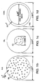
- Figs. 1b-d preferred nozzle designs for gas, oil and coal respectively are shown.
- the nozzle includes a plurality of holes 99 of about 0.22 inches.
- the outer diameter of the nozzle is equal to the diameter of the gun.
- the flow is directed parallel to the axis of the burner.
- the nozzle has a diameter of about 0.94 inches and includes a series of six apertures 101 (diameter about 0.52 inch) from which fuel and atomizing media are introduced into the combustion chamber at an angle of approximately 0 to 25° divergent half angle with respect to the burner axis.
- a nozzle of this type is useful as well with coal-water fuels.
- Fig. 1b for gas the nozzle includes a plurality of holes 99 of about 0.22 inches.
- the outer diameter of the nozzle is equal to the diameter of the gun.
- the flow is directed parallel to the axis of the burner.
- the nozzle has a diameter of about 0.94 inches and includes a series of six apertures 101 (diameter
- the nozzle for pulverized coal, the nozzle consists of two concentrically arranged tubes, wherein the coal and a carrier medium (e.g., air, flue gas and/or steam) is introduced through the central tube and natural gas for the ignition of the coal passed through the outer annular gap.
- a carrier medium e.g., air, flue gas and/or steam
- the inner diameter of the central tube is about 2.29 inch and the width of the gap is about 0.17 inch.
- the primary flow nozzle 22 formed of a duct work in the form of a stainless steel or refractory material tube (diameter 6.5 inches).
- An annular gap of d 1 (about 2.87 inches) is thereby produced by the concentric arrangement.
- Air flow is provided from a supply to a tubing 11 and may be separately metered using valve 13.
- flue effluent may be introduced through piping 17 which similarly may be metered by valve 19 for positively controllable flow into the main supply tube 15.
- the flow in the primary supply pipe 15 may be further controlled by valve 21.
- the flow through valve 21 enters a chamber 16 and flows through an adjustable, movable block-type swirler 18 to create a toroidal vortex as the gas flows through the gap of nozzle 22.
- the swirlers 18 can be adjusted by a lever adjustment means 23 which extends from within the chamber 16 to a handle 25 outside the chamber for easy access.
- Block-type adjustable swirlers enable the swirl number to be varied, for example between about 0 to 2.8.
- the position of the end 31 of the primary flow nozzle 22 is made slidably adjustable with respect to the fuel gun 12 and the secondary 34 and tertiary 42 nozzles. As shown in Fig. 1, solid, the outlet end 31 of the primary nozzle may be positioned behind the gun nozzle 8, e.g., about 3 inches. The end of the primary nozzle 22 may also be extended to a point downstream of the fuel nozzle 8 as shown in phantom. The length of the primary nozzle 22 is L 1 , about 30 inches, and the length of travel is L 2 , about 5 to 6 inches (to a point just beyond the quarl).
- the gas supply pipe 15 may include a means such as bellows 33 (or a length of flexible tubing) enabling easy extension for adjustment of the primary nozzle position.
- secondary nozzle 34 Concentrically arranged with respect to the primary nozzle is secondary nozzle 34, formed of a duct work tube (diameter, about 9.25 inches). The width of the annular gap of the nozzle 34 formed by the concentric arrangement is d 2 , about 1 3/8 inches.
- the air flow for the secondary nozzle is provided through a supply pipe 28 positively metered by a valve 29.
- flue effluent may be introduced through piping 80 which similarly may be metered by valve 82 for positively controllable flow.
- the flow enters a chamber region 35 before treatment with an adjustable block swirler 32 (swirl value 0 to 1.90) and entry into the nozzle area 34 having a length L 3 about 18 inches.
- the chamber 35 is constructed to accommodate the slidably axial motion of the chamber 16 that feeds the primary nozzle 22.
- the block swirler 32 may be controlled by means of a controller 39 which is accessed by handle means 41 held outside the burner structure.
- tertiary nozzle 42 Concentrically arranged with respect to the secondary nozzle is tertiary nozzle 42 formed from duct work to produce an annular nozzle gap having a width d 3 , about 0.875 inches.
- Air is provided to the tertiary nozzle through a supply pipe 43 and may be controlled by a valve 45 to meter flow volume into the chamber 48 before treatment by the block type swirler 40 (swirl value of 0 to 1.39) which as before may be adjusted with the adjusting means 50, accessed by the handle 52.
- flue effluent may be introduced into the tertiary nozzle through piping either instead of the air or to be mixed with the tertiary air.
- the flue effluent may be metered by valve 86 for positively controllable flow with the main supply take 84.
- the length of flow of the air in the nozzle 42 is L 4 , approximately 12 inches.
- the width of the burner quarl is d 4 , approximately 17 inches.
- the flow rate of combustion air in the individual air supplies is typically 15 to 80 lbs/min and is separately metered through the primary, secondary and tertiary nozzles.
- the flow rate through the fuel nozzle is selected above that at which unstable flames occur and below that producing excessive rates of mixing of the auxiliary air with the fuel to occur.
- velocities are about less than 100 m/sec, e.g., 20 - 50 m/sec.
- Nitrogen oxides formation in flames occurs by three main processes.
- the oxygen fixation of atmospheric nitrogen at high temperatures (“thermal NO x “ or “zeldovich NO x “)
- secondly the nitrogen fixation by hydrocarbons to form HCN which leads to NO x formation through reaction with oxygen (“prompt NO x ”)
- thirdly the oxidation of organically bound nitrogen in the fuel (“fuel NO x ”) in oxidizing atmospheres.
- the majority of the air flow is provided through the secondary air supply.
- the burner creates a fluid dynamic flow pattern that enables low NO x production by combustion in two zones, from a single injection point.
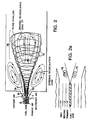
- the flow 70 of the combustible gas mixture provided from the fuel gun 12 is radially stratified by the swirling vortex 72 created by the combination of controlled air flows from the primary, secondary and tertiary nozzles.
- the vortex limits mixing of the fuel with the oxidant mixture and provides a barrier to mixing of the combustible mixture with the bulk of the combustion air in the quarl and the combustion chamber near the burner face.
- the fuel is injected within the vortex as a narrow axial jet which enhances the richness of the fuel/air mixture near the fumier fuel.
- combustion in a first zone 74, in the near field close to the burner quarl is fuel-rich, inhibiting the production of NO x by limiting the available oxygen and enhancing the destruction of NO x that may diffuse from flame lean zones. Little or no NO x is formed in this region because of the reactions of hydrocarbon fragments with any NO x that may form.
- an internal recirculation zone 76 characterized by internal recirculation 77 which is fuel-lean but combustion-product rich, i.e., of low oxygen content.
- the combustion is completed under the low oxygen content conditions (e.g., generally about 2%).
- the products of the fuel rich flame zone mix gradually with the rest of the combustion air in the toroidal recirculation zone produced by the strong rotation of the air issuing through the annular air nozzles of the burner. In this latter flame zone combustion proceeds to completion.
- Heat extraction from the fuel lean flame by thermal radiation produces a flame temperature that avoids hot spots and is maintained at a moderate level, below about 1850 K, typically about 1700K (a low temperature for the formation of thermal NO x ).
- the rotating swirl flow thus fulfills two functions: (1) it stratifies the flow field at the interface of the burning fuel and the air by damping turbulence due to the interaction of a strong radial density gradient, i.e., a low density (hotter) flame in the center surrounded by high density (colder) air flowing in a toroidal fashion, and (2) the creation of a toroidal recirculation zone further downstream of the burner, a zone in which the residual fuel is burned completely.
- stratification is a function of both swirl and density.
- small circulation zones 78 may occur near the burner exit, prior to cumbustion, which provide mixing of the primary concentric flow and the fuel. Downstream in the region of cumbustion, the density of the core is reduced by the combustion and the flows become stratified as discussed.
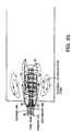
- a recirculation zone 90 of flame effluent is sandwiched between the fuel-rich flame core and the lean tertiary air zone, therefore limiting the mixing of the fuel rich region 91 and the tertiary combustion air 92.
- recirculation of the effluent close to the burner face reduces oxygen content leading to low NO x production, as discussed.
- the external recirculation zone illustrated in Figs. 2-2a is a result of the confinement of the air and fuel within the combustion chamber.
- small circulation zones 93 may occur near the burner outlet.
- the burner as described with respect to Fig. 1 enables fluid dynamics for creating fuel-air mixing as discussed above by a combination of narrow angle axial fuel jets and carefully controlled air flow of specified swirl velocity distribution surrounding the fuel jet. It is also a particular aspect of the invention that the flow from the primary, secondary and tertiary nozzles is positively and separately controllable from a position upstream of the swirlers to enable creation and tuning of the fluid dynamics leading to low NO x emission and is therefore not susceptible to variations in flow rate and volume created by local pressure variations in the combustion chamber. In addition, by variously controlling all of the flows as discussed, the length of the flame in the burner chamber can be controlled.
- the burner is also equipped for the introduction of flue gas recirculated from either the combustion chamber or from positions in the flue gas duct between the combustion chamber and the stack.
- flue gas recirculated from either the combustion chamber or from positions in the flue gas duct between the combustion chamber and the stack By the admixing of recirculated flue gas, the O 2 concentration of the oxidant air is depleted and the flame temperature is reduced, with the consequence of further reduction in the NO x emission.
- the multi-annular design of the burner makes it possible to reduce the amount of flue gas necessary for the effective reduction of the NO x emission because it permits aiming the flue gas into a critical flame region by its introduction through one or more of the annular nozzles specially selected for this purpose (e.g., the nozzle immediately surrounding the fuel jet).
- the burner is also equipped with provision for steam and/or flue gas injection into the fuel stream. Dilution of the fuel concentration with steam or flue gas in the central axial flow fuel jet can produce further reductions in NO x emission. It has been observed experimentally that by admixing a small amount of steam with natural gas prior to injection of fuel into the furnace NO x emission levels chopped by more than 70%.
- the low oxygen levels e.g., less than 4% excess O 2 , less than about 20% total excess air, enable higher efficiency, lower waste gas heat loss since less nitrogen from the air source is heated and in addition high oxygen levels are known to result in increased opacity and corrosiveness in the burner effluent due to the transformation of SO 2 ⁇ SO 3 leading to the formation of sulfuric acid.
- the excess oxygen level is maintained below about 4%.
- High carbon burnout e.g., about 99.5%, for pulverized coal and coal-water slurries have been achieved.
- the excess oxygen level is preferably below about 2%.
- the use of low oxygen levels, 1% or lower does not produce excessive CO levels, i.e., generally about 50 ppm or lower.
- the burner as described enables the following features:
- variable heat extraction along the flame by the use of completely and partially water cooled furnace sections enables the close simulation of large scale flame systems to be made.
- Access to the flame by optical or probe measurements is provided by a 1.0 m long slot at the burner and at every 30 cm length further downstream along the flame tunnel. Measurements made at the "end" of the combustion tunnel are about 6 m from the burner face.
- Input variables such as the fuel and air flows, and the air preheat were maintained by automatic control at their set levels during the experiments. The distribution of air flow, and the swirl degree in the individual burner nozzles were hand controlled.
- the gas temperature distribution in the flames was measured by suction pyrometer and the CO, CO 2 , and NO x concentrations of the gas, sampled at several points in the flame and in the exhaust, were determined by NDIR, (non-dispersive infrared paramagnetic and chemiluminescence continuous analyzers, respectively.
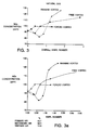
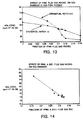
- the effect of the total air swirl characterized by the swirl number, S, is shown in Fig. 3.
- the NO x emission drops to a low value of 82 ppm as the swirl number is maintained at about S 0.6, which is the critical swirl number for the onset of the internal recirculation zone.
- the "Rankine" vortex was found to be the most favorable. In the Rankine vortex the core of the rotating flow rotates as a solid body, with the swirl velocity increasing from the center linearly with radial distance to a maximum at the core boundary, from where it decreases hyperbolically with further increase of the radial distance. Referring to Figs.
- Rankine type vortex flows Swirling flows, termed as Rankine type vortex flows, in which the peak swirl level maximizes at some radial distance from the burner axis.
- Rankine type vortex flows To characterize the effect of the radial displacement of swirl of the combustion air from the flame axis, several model flames were generated by imparting varying swirl degrees to one of the primary, secondary and tertiary air nozzles (while having zero swirl in the other nozzles). The effect of this parameter on NO x concentration is illustrated in Fig. 3a. It is noteworthy, that the optimum configuration for a low NO x concentration was found for a Rankine vortex type swirl velocity distribution. The minimum values of NO x emissions shown in Fig.
- Fig. 4 refers to a correlation between the sum of the angular momenta of the primary, secondary and tertiary air flows each weighted by its normalized radial distance from the burner axis, and the NO x emission is illustrated. However, not all the cases shown to give minimum NO x emission are practicable because some of these result in excessive CO emission and combustion length. A correction for the high CO emission could be made by the additional adjustment of the axial position of the fuel gas nozzle.
- the axial position at which the fuel is introduced within the burner is important in determining the flame structure. Fluid dynamically it affects the interaction of the axial fuel jet and the swirling annular air flow. To investigate the effect of this parameter upon NO x and CO emissions, several flames were investigated in which the location of injection of fuel within the burner was varied.
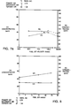
- Figure 5 and 6 (mode 2) illustrate the effect of this variable for the cases of highly swirling and weakly swirling primary air.
- the negative values of the fuel gun positions shown in figures 5 and 6 indicate the distance between the end of the burner face and the fuel gun nozzle tip. A negative value implies that the gun has been retracted into the burner throat. The data shows that the fuel gun position has little effect upon NO x emission level.
- Fig. 9 shows a monotonic increase in NO x emission with increasing primary air fraction.
- An increase flow rate of primary air can be seen to promote early fuel-air mixing and NO x formation in the flame. It is noteworthy, however, that the reduction in primary air flow did not increase CO emission from the flame.
- the conditions represented in Fig. 5 with 51% of the air supplied as primary air give higher NO x values, ranging from 110 to 135 ppm, while CO concentrations are low because of the early aeration of the fuel in this case.
- the primary air fraction is 10% and the NO x levels are in the range of 75 to 85 ppm which shows that even at a low level of swirl degree in the primary air, fuel/air mixing is damped in the near field.
- NO x emission levels increase indicating the early mixing of the fuel with the combustion air. It is noteworthy that for the cases which have low primary air fraction, the lean stage mixing further downstream is inefficient without strong swirl in the tertiary air.
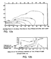
- the iso-concentration lines of CH 4 and O 2 indicate that the fuel was effectively separated from the combustion air and the mixing rate between the two was low. This is reflected by the gradual increase of temperature over a large distance ( ⁇ 1 meter) from the burner inlet. The slow rate of mixing is a result of damping of turbulence through the stratification of the flow by the high swirl imported to both the primary and secondary air jets. As a result of this process, the energy release from the oxidation of fuel is gradual and therefore a relatively low peak flame temperature (1800 K) was obtained consequently, NO x formation was inhibited in this flame (see Fig. 12c).
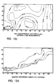
- Fig. 12d illustrates the distribution of the modified Richardson number, defined earlier, in the "optimum" natural gas flame.
- the Ri* values were calculated from measurements of velocity and temperature (density) distributions in the flame. Stratification begins when Ri* > 0.04. As can be seen in the Ri* distribution plotted in Fig. 12d flame stratification was effective for maintaining a fuel rich flame core.
- Recirculation of flue gas through the burner may reduce NO x formation by two mechanisms. Firstly, the increased volume flow rate of gas through the flame reduces the adiabatic flame temperature, and secondly, the large inert content (CO 2 , H 2 O and N 2 ) of the flue gas which depletes the O 2 concentration of the flame gases decreases the rate of NO formation. Deteriorating flame stability (lifted flame and blow off) is normally limiting the amount of recirculation before economic considerations of increased costs of ducting and pumping energy show diminishing returns.
- the multi-annular design of the burner taught herein permits flue gas to be recirculated through any or all of the burner nozzles. By introducing the flue gas through the primary and secondary air nozzle the effect on the fuel/air interface is accentuated and a smaller amount of recirculated gas is needed to achieve the same extent of NO x reduction.
- the high flame stability of the design is also favorable for allowing reduced O 2 concentration of the oxidant surrounding the fuel gas jet.
- a fan capable of recirculating 1500°F temperature flue gas from the post combustion region of the flame tunnel has been used and arrangements were made to inject the recirculated flue gas through the burner compartments serving also for the introduction of the primary and secondary air flows.
- Fig. 13 shows results of NO x emission in the burner flames starting aerodynamically optimized flames (flame type 1) (70ppm NO x ) and increasing the flue gas recirculation in the primary air compartment of the burner up to 16% of the total flue gas flow rate.
- the NO x reduction was even greater when, concurrently, steam (.12 lb/lb fuel gas) was injected into the fuel gas. In some cases where steam is applied to the fuel flow, the amount of flue gas recirculated may be decreased without increasing NO x emission.
- flue effluent may be introduced and metered into any and all of the primary, secondary and tertiary flows or mixed with the fuel.
- Fig. 15 a system is shown wherein all flows are directed in a parallel manner with respect to the burner axis.
- the burner block 69 directs flows from the secondary and tertiary nozzles parallel to the burner axis.
- the burner may be scaled for any size output from, for example, residential burners to large utility burners of, e.g., 200 million BTU.
- Dimensions and flows can be selected from the teachings herein, for example using computer models such as the "Fluent" program available from Creari, Inc., Hanover, NH.
Landscapes
- Engineering & Computer Science (AREA)
- Chemical & Material Sciences (AREA)
- Combustion & Propulsion (AREA)
- Mechanical Engineering (AREA)
- General Engineering & Computer Science (AREA)
- Treating Waste Gases (AREA)
Abstract
Description
- Fuel jet velocity: 50-600 ft/sec.
- Fuel jet angle: 0° - 25°
- Fuel gun position: -45 (retracted) - 0 cm
- Primary air flow rate: 0 - 100%
- Secondary air flow rate: 0 - 100%
- Tertiary air flow rate: 0 - 100%
- Swirl number of primary air: 0 - 2.79
- Swirl number of secondary air: 0 - 1.90
- Swirl number of tertiary air: 0 - 1.39
- type of fuel nozzle
- fuel gun position within burner
- primary to tertiary air ratio
- primary to secondary air ratio
- radial displacement of swirl from flame axis
- the radial distribution of the swirl velocity at the burner exit,
- The primary air flow as a fraction of the total air flow rate,
- the axial position of the fuel gas introduction
| Burner Configuration and Exit Gas Composition for the Optimum Flame | ||
| Percent | Swirl No. | |
| primary air | 19.3 | 2.79 |
| secondary air | 62 | .85 |
| tertiary air | 18.7 | 0 |
| fuel velocity | 50 ft/sec | |
| As measured | 3% O2 | |
| O2 | 1.85% | - |
| CO | 60 ppm | 56 ppm |
| NO | 74 ppm | 70 ppm |
Preferred parameters are:
- Fuel jet velocity :
- about 200 ft/sec
- Fuel jet angle :
- 10° or less
- Fuel gun position :
- retracted
- Mass flow and swirl combustion air distribution:
- 1-20%, preferably 10% primary; 1-20%, preferably 10% secondary; 70-90% tertiary. The air swirl number is preferably: primary - about 0.5 to 2.8; secondary- about 0.5 to 2.0; tertiary - about 1.5 or less
- Burner gas recirculation distribution:
- 5-30% preferably 10% primary; 5-30% preferably 20% secondary; 70-90% tertiary. The gas swirl number is preferably: primary about 0.5-2.8; secondary about 0.5-2.0; tertiary about 1.5 or less.
Claims (44)
- A method for low NOx-emission burning of a fuel within a burner system having a chamber with a single insertion region, said insertion region including afuel nozzle arranged on a burner axis, and first, second and third concentric non-divergent nozzles, each said nozzle arranged at increasing radii from said axis and arranged to introduce flow to said chamber from substantially the same axial location, comprising:flowing a combustible fuel through said fuel nozzle to form a combustible fuel flow along said axis;providing a concentric flow formed by first, second and third successively concentric component flows, including oxidant gases, through said first, second and third concentric nozzles;stratifying said fuel flow and concentric flow to limit mixing of oxidant gases with said fuel flow to maintain a high-temperature fuel rich core zone near said insertion region and to induce mixing with oxidant gases in a lower temperature recirculation zone spaced from said insertion region,said stratifying being achieved by providing the combination of a radial density gradient from low density, high temperature in said core zone close to the axis to higher density, lower temperature spaced radially from said core and swirling said concentric flow,controlling said swirling such that the first concentric flow comprises a fraction of about 0.2 or less of the total concentric flow and the swirl number of said first flow in said first concentric nozzle is higher than the swirl number of the second and third flows in said second and third concentric nozzles, respectively,pyrolizing said fuel in said high-temperature fuel-rich core zone near said insertion region, where the mixing of oxidant gases with said fuel is limited by the stratifying, thereby limiting NOx formation in said high temperature fuel-rich zone; andcombusting the product of said high temperature fuel-rich core zone in said lower-temperature recirculation zone spaced from said insertion region, where mixing of ambient gases is induced, and low-temperature combustion results in limited formation of NOx.
- The method of claim 1 wherein said first concentric component flow has a swirl velocity equal to or greater than said combustible fuel flow, said second concentric component flow has a swirl velocity equal to or less than the swirl velocity of said first concentric component flow and said third concentric component flow has a swirl velocity equal or less than said second concentric component flow.
- The method of claim 1 comprising:providing a first concentric component flow that is about 10 to 20% of the total concentric flow and has a swirl number of about 0.6 or greater,providing a second concentric component flow that is about 10 to 30% of the total concentric flow and has a swirl number of about 0.6 or greater, andproviding a third concentric component flow that is about 40 to 80% of the total concentric flow and has a swirl number in the range of about 1.5 or less.
- The method of claim 3, comprising:providing a first concentric component flow that is about 10% of the total concentric flow and has a swirl number of about 0.6 or higher,providing a second concentric component flow that is about 10% of the total concentric flow and has a swirl number of about 0.60 or higher, andproviding a third concentric component flow that is about 80% of the total concentric flow and has a swirl number of about 1.5 or less.
- The method of claim 4 further comprising:
recirculating flue gas from said combustion by providing said flue gas to at least one of said concentric nozzles. - The method of claim 5 further comprising recirculating about 50% or less of said flue gas.
- The method of claim 1 or 5 further comprising:
providing steam to said fuel flow. - The method of claim 7 wherein said steam is about 25% or less of said fuel flow.
- The method of claim 1 further comprising:
controlling said stratifying to limit substantial mixing of ambient gases with said core zone where the temperature of said core zone is about 1700 K or greater. - The method of claim 9 further comprising:
controlling said stratifying to induce mixing downstream of said core zone in a recirculation zone having a temperature of about 1700 K or less. - The method of claim 1 wherein said fuel is selected from the group consisting of gaseous hydrocarbon fuels, coal and fuel oils.
- A burner system for low NOx-emission burning of fuels, comprising:a chamber with an insertion region, said insertion region including:a fuel nozzle arranged on an axis for providing a flow of a combustible fuel, andfirst, second and third concentric non-divergent nozzlesthe concentrically arranged first nozzle for providing a first concentric component flow about said combustible fuel flow,the concentrically arranged second nozzle, for providing a second concentric component flow about said first component flow,the concentrically arranged third nozzle for providing a third concentric component flow about said second component flowsaid nozzles arranged to introduce said fuel and first, second and third component flows to said chamber at substantially the same axial location,a controller for stratifying to limit mixing of oxidant gases with said fuel flow to maintain a high-temperature fuel rich core zone near said insertion region and to induce mixing with oxidant gases in a lower temperature recirculation zone spaced from said insertion region,said controller including a flow controller for controlling the amount of flow through said first, second and third nozzles, said flow controller constructed such that said first concentric flow comprises a fraction of about 0.2 or less of the total concentric flow,said controller further including a swirl controller for controlling the swirl of said first, second and third concentric component flows, said swirl controller being constructed such that the swirl velocity of said first flow in said first nozzle is higher than the swirl velocity of the second and third flows in said second and third nozzles, respectively,said concentric component flows, in combination with a radial density gradient from a low density high temperature in said core to higher density, lower temperature spaced radially from said core, effective to bring about a condition of stratification, whereby mixing of ambient gas with said combustible fuel flow is limited to maintain a high temperature fuel rich core zone near said insertion region and to induce mixing in a lower temperature recirculation zone spaced from the insertion region, andan ignitor for initiating burning of said combustible fuel flow.
- The burner of claim 12 wherein said swirl controller is constructed to provide said first concentric component flow that has a swirl velocity equal to or greater than said fuel flow, second concentric component flow that has a swirl velocity equal to or less than the swirl of said first concentric component flow and third concentric component flow that has a swirl equal or less than said second concentric component flow.
- The burner of claim 13 wherein said swirl controller is constructed for providing a first concentric component flow that is about 10 to 20% of the total concentric flow and has a swirl number in the range of about 0.6 or greater,a second concentric component flow that is about 10 to 30% of the total concentric flow and has a swirl number in the range of about 0.6 or greater, anda third concentric component flow that is about 40 to 80% of the total concentric flow and has a swirl number in the range of 1.5 or less.
- The burner of claim 14 whereinsaid swirl controller provides a first concentric component flow that is about 10% of the total concentric flow and has a swirl number of about 0.6 or higher,a second concentric component flow that is about 10% of the total concentric flow and has a swirl number of about 0.60 or higher, anda third concentric component flow that is about 80% of the total concentric flow and has a swirl number of about 1.5 or lower.
- The burner of claim 12 or 14 further comprising:
a recirculating fan for recirculating flue gas from said combustion and providing said flue gas to at least one of said concentric nozzles. - The burner of claim 16 wherein said recirculating fan is constructed for recirculating about 50% or less of said flue gas.
- The burner of claim 12 or 14 further comprising a steam supply for providing steam to said fuel flow.
- The burner of claim 18 comprising a meter constructed for controlling said core flow to provide about 25% or less steam in said fuel flow.
- The burner of claim 12 further comprising flue gas supply for providing flue gas to said fuel flow.
- The burner of claim 12 wherein said controller is constructed to stratify to limit substantial mixing of ambient gases with said core zone where the temperature of said core zone about 1700 K or greater.
- The burner of claim 21 wherein said controller is constructed to induce mixing downstream of said core zone in a recirculation zone having a temperature of about 1700 K or less.
- The burner of claim 12 further comprises a supply of fuel selected from the group consisting of gaseous hydrocarbon fuel, coal and fuel oils.
- The burner of claim 12 wherein said fuel nozzle produces a combustible fuel flow with a half angle of about 30 degrees or less.
- The burner of claim 24 wherein said fuel nozzle produces a combustible fuel flow with a half angle of about 20 degrees or less.
- The burner of claim 12 wherein the flow rate of said first, second and third concentric component flows are separately adjustable.
- The burner of claim 12 wherein the swirl numbers of said first, second and third concentric component flows are separately adjustable.
- The method of claim 1 wherein said burner has a single insertion region, wherein all flows are introduced to the combustion chamber upstream of the core zone.
- The burner of claim 12 wherein said burner has a single insertion region, wherein all flows are introduced to the combustion chamber upstream of the core zone.
- The method of claim 1 wherein said stratifying step includes:providing a fuel flow along an axis and a concentric flow, including oxidant gases, disposed about said fuel flow, said fuel flow and concentric flow being introduced into a chamber at substantially the same axial location at an insertion region,stratifying said fuel flow and concentric flow to limit mixing of oxidant gases with said fuel flow to maintain a high temperature fuel rich core zone near said insertion region and induce mixing with oxidant gases in a lower temperature recirculation zone spaced from said insertion region,said stratifying being achieved by providing the combination of a radial density gradient from low density, high temperature in said core zone close to said axis to higher density, lower temperature spaced radially from said core zone and swirling said concentric flow;controlling said stratifying to limit mixing such that said fuel is substantially confined within a region about the core where the modified Richardson number of said concentric flow is about 0.04 or greater.
- The method of claim 30 comprising controlling said stratifying to limit mixing such that the mole fraction of fuel is about 0.20 or less in the region where said modified Richardson number of said swirling flow is about 0.04 or greater.
- The method of claim 30 comprising controlling said stratifying to limit mixing such that the modified Richardson number increases with radial distance from said core to a value of about 0.80.
- The method of claim 32 comprising controlling said stratifying to limit mixing such that the mole fraction of fuel is about 0.10 or less in the region where the modified Richardson number of said swirling flow is about 0.80.
- The method of claim 1 comprising
determining the degree of stratification by determining the modified Richardson number. - The method of any one of the claims 30 to 34, comprising
controlling said stratifying by controlling the fraction and swirl number of said component flows. - The method of claim 35 comprising:providing first, second and third successively concentric flows;controlling said multiple component flows such that the first component flow which is closest to said axis comprises a fraction of about 0.2 or less of the total stratifying flow, andsaid third concentric component flow is a greater fraction of said total flow than either the first or second flow.
- The method of claim 30 or 34 comprising:
recirculating flue gas from said chamber through at least one of said component flows. - The method of claim 30 or 34 comprising:
providing steam to said fuel flow. - The method of claim 30 or 34 comprising
providing said fuel flow through multiple ports arranged about the axis. - The method of claim 30 or 34 comprising:
providing a fuel flow including fuel oil. - The method of claim 30 or 34 comprising:
providing a fuel flow including coal. - The method of claim 30 or 34 comprising:
providing a fuel flow including a gaseous hydrocarbon. - The method of claim 1 wherein said step of flowing a combustible fuel through said fuel nozzle includes introducing said combustible fuel flow at a divergent half angle of approximately 0 to 25° with respect to said burner axis.
- The burner system of claim 12 wherein said fuel nozzle is adapted to introduce said combustible fuel flow at a divergent half angle of approximately 0 to 25° with respect to said burner axis.
Applications Claiming Priority (5)
| Application Number | Priority Date | Filing Date | Title |
|---|---|---|---|
| US59367990A | 1990-10-05 | 1990-10-05 | |
| US593679 | 1990-10-05 | ||
| US77173991A | 1991-10-04 | 1991-10-04 | |
| US771739 | 1991-10-04 | ||
| PCT/US1991/007406 WO1992006328A1 (en) | 1990-10-05 | 1991-10-07 | Combustion system for reduction of nitrogen oxides |
Publications (3)
| Publication Number | Publication Date |
|---|---|
| EP0550700A1 EP0550700A1 (en) | 1993-07-14 |
| EP0550700A4 EP0550700A4 (en) | 1993-08-25 |
| EP0550700B1 true EP0550700B1 (en) | 1998-07-22 |
Family
ID=27081766
Family Applications (1)
| Application Number | Title | Priority Date | Filing Date |
|---|---|---|---|
| EP92902517A Expired - Lifetime EP0550700B1 (en) | 1990-10-05 | 1991-10-07 | Combustion system for reduction of nitrogen oxides |
Country Status (6)
| Country | Link |
|---|---|
| US (1) | US5411394A (en) |
| EP (1) | EP0550700B1 (en) |
| AT (1) | ATE168759T1 (en) |
| CA (1) | CA2093316C (en) |
| DE (1) | DE69129858T2 (en) |
| WO (1) | WO1992006328A1 (en) |
Families Citing this family (88)
| Publication number | Priority date | Publication date | Assignee | Title |
|---|---|---|---|---|
| US5333574A (en) * | 1991-09-11 | 1994-08-02 | Mark Iv Transportation Products Corporation | Compact boiler having low NOX emissions |
| DE4217879A1 (en) * | 1992-05-29 | 1993-12-02 | Babcock Energie Umwelt | Burner for dusty fuel |
| EP0599395A1 (en) * | 1992-11-20 | 1994-06-01 | WITTEVEEN, Gustaaf Jan | Low NOx combustor |
| US5511971A (en) * | 1993-08-23 | 1996-04-30 | Benz; Robert P. | Low nox burner process for boilers |
| USRE36373E (en) * | 1993-08-23 | 1999-11-02 | Benz; Robert P. | Low NOx burner process for boilers |
| US5426933A (en) * | 1994-01-11 | 1995-06-27 | Solar Turbines Incorporated | Dual feed injection nozzle with water injection |
| US5560305A (en) * | 1994-12-15 | 1996-10-01 | The Boc Group, Inc. | Burner block and method for furnace |
| DE19527083A1 (en) * | 1995-07-25 | 1997-01-30 | Lentjes Kraftwerkstechnik | Process and burner for reducing NO¶x¶ formation from coal dust combustion |
| DE19536672A1 (en) * | 1995-09-30 | 1997-04-03 | Abb Research Ltd | Method for burning fuel in main stream of combustion air |
| RO117734B1 (en) | 1996-06-19 | 2002-06-28 | Comb Engineering Inc Windsor | Method for controlling a radially stratified flame core burner |
| US5829369A (en) * | 1996-11-12 | 1998-11-03 | The Babcock & Wilcox Company | Pulverized coal burner |
| DE59708821D1 (en) * | 1997-03-18 | 2003-01-09 | Alstom Switzerland Ltd | Boiler plant for heat generation |
| US6007326A (en) * | 1997-08-04 | 1999-12-28 | Praxair Technology, Inc. | Low NOx combustion process |
| FR2772118B1 (en) * | 1997-12-05 | 2001-08-17 | Saint Gobain Vitrage | COMBUSTION PROCESS AND FUEL SPRAY BURNER IMPLEMENTING SUCH A METHOD |
| EP0931979A1 (en) * | 1998-01-23 | 1999-07-28 | DVGW Deutscher Verein des Gas- und Wasserfaches -Technisch-wissenschaftliche Vereinigung- | Method and apparatus for supressing flame and pressure fluctuations in a furnace |
| JP3343855B2 (en) * | 1998-01-30 | 2002-11-11 | 株式会社日立製作所 | Pulverized coal combustion burner and combustion method of pulverized coal combustion burner |
| US20080286704A1 (en) * | 1998-11-18 | 2008-11-20 | Hermann Bruggendick | Method of burning a nitrogen-containing fuel |
| EP1217299B1 (en) * | 1999-08-16 | 2011-11-16 | Nippon Furnace Co., Ltd. | Device and method for feeding fuel |
| US6383461B1 (en) * | 1999-10-26 | 2002-05-07 | John Zink Company, Llc | Fuel dilution methods and apparatus for NOx reduction |
| US6453830B1 (en) * | 2000-02-29 | 2002-09-24 | Bert Zauderer | Reduction of nitrogen oxides by staged combustion in combustors, furnaces and boilers |
| WO2001075361A1 (en) | 2000-03-31 | 2001-10-11 | Aqua-Chem, Inc. | Low pollution emission burner |
| EP1219895A1 (en) * | 2000-12-28 | 2002-07-03 | Oertli Induflame AG | Combustion process with reduced nitrogen oxide emissions |
| US6699029B2 (en) | 2001-01-11 | 2004-03-02 | Praxair Technology, Inc. | Oxygen enhanced switching to combustion of lower rank fuels |
| US20020127505A1 (en) | 2001-01-11 | 2002-09-12 | Hisashi Kobayashi | Oxygen enhanced low nox combustion |
| US6699030B2 (en) | 2001-01-11 | 2004-03-02 | Praxair Technology, Inc. | Combustion in a multiburner furnace with selective flow of oxygen |
| US6699031B2 (en) | 2001-01-11 | 2004-03-02 | Praxair Technology, Inc. | NOx reduction in combustion with concentrated coal streams and oxygen injection |
| US6702569B2 (en) | 2001-01-11 | 2004-03-09 | Praxair Technology, Inc. | Enhancing SNCR-aided combustion with oxygen addition |
| US6551098B2 (en) * | 2001-02-22 | 2003-04-22 | Rheem Manufacturing Company | Variable firing rate fuel burner |
| US6908298B1 (en) | 2001-10-30 | 2005-06-21 | Owen W. Dykema | Air-fuel injection system for stable combustion |
| FR2837263B1 (en) * | 2002-03-12 | 2004-09-24 | Air Liquide | PROCESS FOR IMPLEMENTATION OF A HEAT RECOVERY BOILER |
| ES2566798T3 (en) * | 2002-05-15 | 2016-04-15 | Praxair Technology, Inc. | Combustion with low NOx emissions |
| CA2485570C (en) | 2002-05-15 | 2009-12-22 | Praxair Technology, Inc. | Combustion with reduced carbon in the ash |
| US20030234455A1 (en) * | 2002-06-24 | 2003-12-25 | Mieney Harry R. | Non-contacting fuel vaporizer |
| US6895756B2 (en) * | 2002-09-13 | 2005-05-24 | The Boeing Company | Compact swirl augmented afterburners for gas turbine engines |
| US6968695B2 (en) * | 2002-09-13 | 2005-11-29 | The Boeing Company | Compact lightweight ramjet engines incorporating swirl augmented combustion with improved performance |
| US6907724B2 (en) * | 2002-09-13 | 2005-06-21 | The Boeing Company | Combined cycle engines incorporating swirl augmented combustion for reduced volume and weight and improved performance |
| US6820411B2 (en) * | 2002-09-13 | 2004-11-23 | The Boeing Company | Compact, lightweight high-performance lift thruster incorporating swirl-augmented oxidizer/fuel injection, mixing and combustion |
| EP1585920B1 (en) * | 2003-01-21 | 2010-10-20 | L'AIR LIQUIDE, Société Anonyme pour l'Etude et l'Exploitation des Procédés Georges Claude | Process and apparatus for oxygen enrichment in fuel conveying gases |
| US7163392B2 (en) * | 2003-09-05 | 2007-01-16 | Feese James J | Three stage low NOx burner and method |
| US7484956B2 (en) * | 2003-09-16 | 2009-02-03 | Praxair Technology, Inc. | Low NOx combustion using cogenerated oxygen and nitrogen streams |
| DE102004003343A1 (en) * | 2004-01-22 | 2005-08-11 | Linde Ag | Flexible parallel flow burner with swirl chamber |
| US20050227195A1 (en) * | 2004-04-08 | 2005-10-13 | George Kenneth R | Combustion burner assembly having low oxides of nitrogen emission |
| US7168947B2 (en) * | 2004-07-06 | 2007-01-30 | General Electric Company | Methods and systems for operating combustion systems |
| US7264466B2 (en) * | 2004-09-10 | 2007-09-04 | North American Manufacturing Company | Method and apparatus for radiant tube combustion |
| US7766649B2 (en) * | 2005-03-07 | 2010-08-03 | Gas Technology Institute | Multi-ported, internally recuperated burners for direct flame impingement heating applications |
| WO2006107209A1 (en) * | 2005-04-05 | 2006-10-12 | Sargas As | Low co2 thermal powerplant |
| US20060275724A1 (en) * | 2005-06-02 | 2006-12-07 | Joshi Mahendra L | Dynamic burner reconfiguration and combustion system for process heaters and boilers |
| US7430970B2 (en) * | 2005-06-30 | 2008-10-07 | Larue Albert D | Burner with center air jet |
| US20070269755A2 (en) * | 2006-01-05 | 2007-11-22 | Petro-Chem Development Co., Inc. | Systems, apparatus and method for flameless combustion absent catalyst or high temperature oxidants |
| US8215949B2 (en) * | 2006-05-17 | 2012-07-10 | Majed Toqan | Combustion stabilization systems |
| US20120266792A1 (en) * | 2006-05-17 | 2012-10-25 | Majed Toqan | Combustion Stabilization Systems |
| FR2903479A1 (en) * | 2006-07-06 | 2008-01-11 | Air Liquide | DIRECT FLAME BURNER AND METHOD OF IMPLEMENTING THE SAME |
| US20080128547A1 (en) * | 2006-12-05 | 2008-06-05 | Pratt & Whitney Rocketdyne, Inc. | Two-stage hypersonic vehicle featuring advanced swirl combustion |
| US7762077B2 (en) * | 2006-12-05 | 2010-07-27 | Pratt & Whitney Rocketdyne, Inc. | Single-stage hypersonic vehicle featuring advanced swirl combustion |
| US7762058B2 (en) * | 2007-04-17 | 2010-07-27 | Pratt & Whitney Rocketdyne, Inc. | Ultra-compact, high performance aerovortical rocket thruster |
| US7690192B2 (en) | 2007-04-17 | 2010-04-06 | Pratt & Whitney Rocketdyne, Inc. | Compact, high performance swirl combustion rocket engine |
| EP2080952A1 (en) * | 2008-01-17 | 2009-07-22 | L'AIR LIQUIDE, Société Anonyme pour l'Etude et l'Exploitation des Procédés Georges Claude | Burner and method for alternately implementing an oxycombustion and an air combustion |
| US7775791B2 (en) * | 2008-02-25 | 2010-08-17 | General Electric Company | Method and apparatus for staged combustion of air and fuel |
| EP2107311A1 (en) * | 2008-04-01 | 2009-10-07 | Siemens Aktiengesellschaft | Size scaling of a burner |
| WO2009136366A2 (en) * | 2008-05-05 | 2009-11-12 | L'air Liquide Societe Anonyme Pour L'etude Et L'exploitation Des Procedes Georges Claude | Device and method of combusting solid fuel with oxygen |
| US20100035193A1 (en) * | 2008-08-08 | 2010-02-11 | Ze-Gen, Inc. | Method and system for fuel gas combustion, and burner for use therein |
| EP2326878A2 (en) * | 2008-09-26 | 2011-06-01 | Air Products and Chemicals, Inc. | Combustion system with precombustor for recycled flue gas |
| US20100077942A1 (en) * | 2008-09-26 | 2010-04-01 | Air Products And Chemicals, Inc. | Oxy/fuel combustion system with little or no excess oxygen |
| DE102009014223A1 (en) * | 2009-03-25 | 2010-09-30 | Hitachi Power Europe Gmbh | Firing system of a designed for the oxyfuel operation steam generator |
| US8607570B2 (en) * | 2009-05-06 | 2013-12-17 | General Electric Company | Airblown syngas fuel nozzle with diluent openings |
| US20100281869A1 (en) * | 2009-05-06 | 2010-11-11 | Mark Allan Hadley | Airblown Syngas Fuel Nozzle With Diluent Openings |
| US20100281872A1 (en) * | 2009-05-06 | 2010-11-11 | Mark Allan Hadley | Airblown Syngas Fuel Nozzle With Diluent Openings |
| US20110045420A1 (en) * | 2009-08-21 | 2011-02-24 | Alstom Technology Ltd | Burner monitor and control |
| PL2513345T3 (en) * | 2009-11-26 | 2016-07-29 | Linde Ag | Method for heatng a blast furnace stove |
| MY185043A (en) | 2011-01-31 | 2021-04-30 | Ihi Corp | Burner device for high-temparature air combustion |
| DE102011011207A1 (en) * | 2011-02-14 | 2012-08-16 | Air Liquide Deutschland Gmbh | Burner for uniform heating of a long oven |
| EP2500640A1 (en) | 2011-03-16 | 2012-09-19 | L'AIR LIQUIDE, Société Anonyme pour l'Etude et l'Exploitation des Procédés Georges Claude | Low NOx combustion process and burner therefor |
| US8920159B2 (en) * | 2011-11-23 | 2014-12-30 | Honeywell International Inc. | Burner with oxygen and fuel mixing apparatus |
| US20130327050A1 (en) * | 2012-06-07 | 2013-12-12 | General Electric Company | Controlling flame stability of a gas turbine generator |
| US10215412B2 (en) * | 2012-11-02 | 2019-02-26 | General Electric Company | System and method for load control with diffusion combustion in a stoichiometric exhaust gas recirculation gas turbine system |
| US9909755B2 (en) * | 2013-03-15 | 2018-03-06 | Fives North American Combustion, Inc. | Low NOx combustion method and apparatus |
| CN103272728B (en) * | 2013-06-09 | 2017-01-25 | 潍柴动力股份有限公司 | Silicon controlled rectifier (SCR) system and urea spray nozzle thereof |
| EP2821699A1 (en) * | 2013-07-02 | 2015-01-07 | Haldor Topsøe A/S | Mixing of recycle gas with fuel gas to a burner |
| US10281140B2 (en) | 2014-07-15 | 2019-05-07 | Chevron U.S.A. Inc. | Low NOx combustion method and apparatus |
| WO2016046074A1 (en) | 2014-09-26 | 2016-03-31 | Innecs B.V. | Burner |
| US10274194B2 (en) * | 2014-12-19 | 2019-04-30 | Utilization Technology Development, Nfp | Methods and systems for reducing emissions of nitrogen oxides from ribbon burners |
| FR3039254B1 (en) * | 2015-07-24 | 2021-10-08 | Snecma | COMBUSTION CHAMBER CONTAINING ADDITIONAL INJECTION DEVICES OPENING DIRECTLY INTO CORNER RECIRCULATION ZONES, TURBOMACHINE INCLUDING IT, AND PROCESS FOR SUPPLYING FUEL FROM THE SAME |
| US10753267B2 (en) * | 2018-01-26 | 2020-08-25 | Quest Engines, LLC | Method and apparatus for producing stratified streams |
| CN108507917B (en) * | 2018-04-20 | 2021-12-03 | 南京恒瑞环保科技有限公司 | Method for detecting dust removal capacity of converter primary flue gas dust removal system |
| US11866361B2 (en) * | 2019-10-29 | 2024-01-09 | Honeywell International Inc. | Fuel gas and oxygen burner |
| US12359807B2 (en) | 2019-12-20 | 2025-07-15 | Jupiter Oxygen Corporation | Combustion system comprising an annular shroud burner |
| US10845052B1 (en) | 2019-12-20 | 2020-11-24 | Jupiter Oxygen Corporation | Combustion system comprising an annular shroud burner |
| RU2757705C1 (en) * | 2021-01-13 | 2021-10-20 | Роман Лазирович Илиев | Double-layer vortex countercurrent flow burner |
Family Cites Families (22)
| Publication number | Priority date | Publication date | Assignee | Title |
|---|---|---|---|---|
| US2515845A (en) * | 1946-06-25 | 1950-07-18 | Shell Dev | Flame pocket fluid fuel burner |
| FR1094871A (en) * | 1959-01-22 | 1955-05-25 | Thomson Houston Comp Francaise | Improvements to injected fuel combustion devices |
| US3576384A (en) * | 1968-11-29 | 1971-04-27 | British American Oil Co | Multinozzle system for vortex burners |
| DE2724532A1 (en) * | 1977-05-31 | 1978-12-14 | Peabody Environmental Systems | Combined burner for firing oil and gas - has blades imposing rotating flow to ensure mixing and efficient burning |
| SU817383A1 (en) * | 1977-10-18 | 1981-03-30 | Kotler Vladlen R | Solid-fuel burning method |
| US4270895A (en) * | 1978-06-29 | 1981-06-02 | Foster Wheeler Energy Corporation | Swirl producer |
| DE2933040C2 (en) * | 1979-08-16 | 1988-12-22 | L. & C. Steinmüller GmbH, 5270 Gummersbach | Method for igniting a coal dust round burner flame |
| DE2933060C2 (en) * | 1979-08-16 | 1987-01-22 | L. & C. Steinmüller GmbH, 5270 Gummersbach | Burners for the combustion of dust-like fuels |
| US4845940A (en) * | 1981-02-27 | 1989-07-11 | Westinghouse Electric Corp. | Low NOx rich-lean combustor especially useful in gas turbines |
| US4422391A (en) * | 1981-03-12 | 1983-12-27 | Kawasaki Jukogyo Kabushiki Kaisha | Method of combustion of pulverized coal by pulverized coal burner |
| DE3125901A1 (en) * | 1981-07-01 | 1983-01-20 | Deutsche Babcock Ag, 4200 Oberhausen | BURNER FOR BURNING DUST-MADE FUELS |
| US4523530A (en) * | 1982-02-26 | 1985-06-18 | Sumitomo Metal Industries, Ltd. | Powdery coal burner |
| US4407205A (en) * | 1982-04-30 | 1983-10-04 | Beaufrere Albert H | Regeneratively cooled coal combustor/gasifier with integral dry ash removal |
| US4569295A (en) * | 1983-01-18 | 1986-02-11 | Stubinen Utveckling Ab | Process and a means for burning solid fuels, preferably coal, turf or the like, in pulverized form |
| JPS60174408A (en) * | 1984-02-20 | 1985-09-07 | Kawasaki Heavy Ind Ltd | Two-stage combustion air hole for combustion chamber |
| JPS60226609A (en) * | 1984-04-23 | 1985-11-11 | Babcock Hitachi Kk | Combustion device for coal |
| US4539918A (en) * | 1984-10-22 | 1985-09-10 | Westinghouse Electric Corp. | Multiannular swirl combustor providing particulate separation |
| US4604052A (en) * | 1985-04-29 | 1986-08-05 | The United States Of America As Represented By The United States Department Of Energy | Dual-water mixture fuel burner |
| FR2581444B1 (en) * | 1985-05-03 | 1988-11-10 | Charbonnages De France | PROCESS FOR THE COMBUSTION OF FLUID FUELS AND A TURBULENCE BURNER SUITABLE FOR ITS IMPLEMENTATION |
| EP0233680B2 (en) * | 1986-01-08 | 1993-10-27 | Hitachi, Ltd. | Method of and apparatus for combusting coal-water mixture |
| US4915619A (en) * | 1988-05-05 | 1990-04-10 | The Babcock & Wilcox Company | Burner for coal, oil or gas firing |
| US4927352A (en) * | 1988-07-19 | 1990-05-22 | Landy Chung | Boiler furnace air register |
-
1991
- 1991-10-07 AT AT92902517T patent/ATE168759T1/en not_active IP Right Cessation
- 1991-10-07 WO PCT/US1991/007406 patent/WO1992006328A1/en not_active Ceased
- 1991-10-07 DE DE69129858T patent/DE69129858T2/en not_active Expired - Lifetime
- 1991-10-07 CA CA002093316A patent/CA2093316C/en not_active Expired - Lifetime
- 1991-10-07 EP EP92902517A patent/EP0550700B1/en not_active Expired - Lifetime
-
1993
- 1993-10-05 US US08/131,867 patent/US5411394A/en not_active Expired - Lifetime
Also Published As
| Publication number | Publication date |
|---|---|
| ATE168759T1 (en) | 1998-08-15 |
| WO1992006328A1 (en) | 1992-04-16 |
| CA2093316C (en) | 2002-12-03 |
| DE69129858D1 (en) | 1998-08-27 |
| DE69129858T2 (en) | 1998-12-03 |
| CA2093316A1 (en) | 1992-04-06 |
| EP0550700A4 (en) | 1993-08-25 |
| US5411394A (en) | 1995-05-02 |
| EP0550700A1 (en) | 1993-07-14 |
Similar Documents
| Publication | Publication Date | Title |
|---|---|---|
| US5411394A (en) | Combustion system for reduction of nitrogen oxides | |
| CA2485934C (en) | Low nox combustion | |
| US5470224A (en) | Apparatus and method for reducing NOx , CO and hydrocarbon emissions when burning gaseous fuels | |
| CA2492115A1 (en) | Enhancing sncr-aided combustion with oxygen addition | |
| WO2004008028A2 (en) | Oxygen enhanced combustion of lower rank fuels | |
| Yan et al. | Influence of inner and outer secondary air ratio on flow and combustion characteristics of a swirl burner in a 29áMW pulverized coal boiler | |
| Qi et al. | Influence of division cone angles between the fuel-rich and the fuel-lean ducts on gas–particle flow and combustion near swirl burners | |
| US5960724A (en) | Method for effecting control over a radially stratified flame core burner | |
| Xing et al. | Structure of reaction zone of normal temperature air flameless combustion in a 2 ton/h coal-fired boiler furnace | |
| Toqan et al. | Low NOx emission from radially stratified natural gas-air turbulent diffusion flames | |
| EP0073265A1 (en) | Method and apparatus for burning a fuel | |
| Ahn et al. | An experimental study on combustion processes and NOx emission characteristics of the Air-Staged burner | |
| Shihadeh et al. | Low NOx emission from aerodynamically staged oil-air turbulent diffusion flames | |
| CN117606022A (en) | Ammonia burner, combustion system and combustion method | |
| Cha et al. | An experiment analysis of MILD combustion with liquid fuel spray in a combustion vessel | |
| Yuan et al. | Experimental investigation on gas-particle flow and combustion characteristics from a pre-combustion chamber burner coupled with in-furnace radial air staging: optimization of secondary air ratio | |
| Gupta et al. | The effect of swirl and nozzle geometry on the structure of flames and NO (x) emission | |
| JP2000039108A (en) | LOW NOx BURNER | |
| Guo et al. | Numerical study of NOx formation characteristics on the 35 MW staged oxy-coal combustion | |
| Yılmaz | Assessment of Combustion and Emission Characteristics of Various Gas Mixtures under Different Combustion Techniques | |
| Bee´ r et al. | Development of the RSFC Low NOx Burner: From Fundamentals to Industrial Applications | |
| BEÉR | Low NOx Burners for Boilers, Furnaces | |
| Bee´ r et al. | Development of the Radially Stratified Flame Core Low NO x Burner: From Fundamentals to Industrial Applications | |
| Motevalli | Effects of gas turbine combustor geometry variation on pollutant emission using a multi-annular, telescopic, swirl combustor | |
| HIROYASU | Effect of fuel properties on spray combustion |
Legal Events
| Date | Code | Title | Description |
|---|---|---|---|
| PUAI | Public reference made under article 153(3) epc to a published international application that has entered the european phase |
Free format text: ORIGINAL CODE: 0009012 |
|
| 17P | Request for examination filed |
Effective date: 19930419 |
|
| AK | Designated contracting states |
Kind code of ref document: A1 Designated state(s): AT BE CH DE DK ES FR GB GR IT LI LU NL SE |
|
| A4 | Supplementary search report drawn up and despatched |
Effective date: 19930707 |
|
| AK | Designated contracting states |
Kind code of ref document: A4 Designated state(s): AT BE CH DE DK ES FR GB GR IT LI LU NL SE |
|
| 17Q | First examination report despatched |
Effective date: 19940728 |
|
| GRAG | Despatch of communication of intention to grant |
Free format text: ORIGINAL CODE: EPIDOS AGRA |
|
| GRAG | Despatch of communication of intention to grant |
Free format text: ORIGINAL CODE: EPIDOS AGRA |
|
| GRAG | Despatch of communication of intention to grant |
Free format text: ORIGINAL CODE: EPIDOS AGRA |
|
| GRAH | Despatch of communication of intention to grant a patent |
Free format text: ORIGINAL CODE: EPIDOS IGRA |
|
| GRAH | Despatch of communication of intention to grant a patent |
Free format text: ORIGINAL CODE: EPIDOS IGRA |
|
| GRAA | (expected) grant |
Free format text: ORIGINAL CODE: 0009210 |
|
| ITF | It: translation for a ep patent filed | ||
| AK | Designated contracting states |
Kind code of ref document: B1 Designated state(s): AT BE CH DE DK ES FR GB GR IT LI LU NL SE |
|
| PG25 | Lapsed in a contracting state [announced via postgrant information from national office to epo] |
Ref country code: NL Free format text: LAPSE BECAUSE OF FAILURE TO SUBMIT A TRANSLATION OF THE DESCRIPTION OR TO PAY THE FEE WITHIN THE PRESCRIBED TIME-LIMIT Effective date: 19980722 Ref country code: LI Free format text: LAPSE BECAUSE OF FAILURE TO SUBMIT A TRANSLATION OF THE DESCRIPTION OR TO PAY THE FEE WITHIN THE PRESCRIBED TIME-LIMIT Effective date: 19980722 Ref country code: GR Free format text: LAPSE BECAUSE OF FAILURE TO SUBMIT A TRANSLATION OF THE DESCRIPTION OR TO PAY THE FEE WITHIN THE PRESCRIBED TIME-LIMIT Effective date: 19980722 Ref country code: FR Free format text: LAPSE BECAUSE OF FAILURE TO SUBMIT A TRANSLATION OF THE DESCRIPTION OR TO PAY THE FEE WITHIN THE PRESCRIBED TIME-LIMIT Effective date: 19980722 Ref country code: ES Free format text: THE PATENT HAS BEEN ANNULLED BY A DECISION OF A NATIONAL AUTHORITY Effective date: 19980722 Ref country code: CH Free format text: LAPSE BECAUSE OF FAILURE TO SUBMIT A TRANSLATION OF THE DESCRIPTION OR TO PAY THE FEE WITHIN THE PRESCRIBED TIME-LIMIT Effective date: 19980722 Ref country code: BE Free format text: LAPSE BECAUSE OF FAILURE TO SUBMIT A TRANSLATION OF THE DESCRIPTION OR TO PAY THE FEE WITHIN THE PRESCRIBED TIME-LIMIT Effective date: 19980722 Ref country code: AT Free format text: LAPSE BECAUSE OF FAILURE TO SUBMIT A TRANSLATION OF THE DESCRIPTION OR TO PAY THE FEE WITHIN THE PRESCRIBED TIME-LIMIT Effective date: 19980722 |
|
| REF | Corresponds to: |
Ref document number: 168759 Country of ref document: AT Date of ref document: 19980815 Kind code of ref document: T |
|
| REG | Reference to a national code |
Ref country code: CH Ref legal event code: EP |
|
| REF | Corresponds to: |
Ref document number: 69129858 Country of ref document: DE Date of ref document: 19980827 |
|
| PG25 | Lapsed in a contracting state [announced via postgrant information from national office to epo] |
Ref country code: LU Free format text: LAPSE BECAUSE OF NON-PAYMENT OF DUE FEES Effective date: 19981007 |
|
| PG25 | Lapsed in a contracting state [announced via postgrant information from national office to epo] |
Ref country code: DK Free format text: LAPSE BECAUSE OF FAILURE TO SUBMIT A TRANSLATION OF THE DESCRIPTION OR TO PAY THE FEE WITHIN THE PRESCRIBED TIME-LIMIT Effective date: 19981022 |
|
| EN | Fr: translation not filed | ||
| NLV1 | Nl: lapsed or annulled due to failure to fulfill the requirements of art. 29p and 29m of the patents act | ||
| REG | Reference to a national code |
Ref country code: CH Ref legal event code: PL |
|
| PLBE | No opposition filed within time limit |
Free format text: ORIGINAL CODE: 0009261 |
|
| STAA | Information on the status of an ep patent application or granted ep patent |
Free format text: STATUS: NO OPPOSITION FILED WITHIN TIME LIMIT |
|
| 26N | No opposition filed | ||
| REG | Reference to a national code |
Ref country code: GB Ref legal event code: IF02 |
|
| PGFP | Annual fee paid to national office [announced via postgrant information from national office to epo] |
Ref country code: DE Payment date: 20101027 Year of fee payment: 20 |
|
| PGFP | Annual fee paid to national office [announced via postgrant information from national office to epo] |
Ref country code: IT Payment date: 20101027 Year of fee payment: 20 Ref country code: SE Payment date: 20101027 Year of fee payment: 20 Ref country code: GB Payment date: 20101025 Year of fee payment: 20 |
|
| REG | Reference to a national code |
Ref country code: DE Ref legal event code: R071 Ref document number: 69129858 Country of ref document: DE |
|
| REG | Reference to a national code |
Ref country code: DE Ref legal event code: R071 Ref document number: 69129858 Country of ref document: DE |
|
| REG | Reference to a national code |
Ref country code: GB Ref legal event code: PE20 Expiry date: 20111006 |
|
| REG | Reference to a national code |
Ref country code: SE Ref legal event code: EUG |
|
| PG25 | Lapsed in a contracting state [announced via postgrant information from national office to epo] |
Ref country code: GB Free format text: LAPSE BECAUSE OF EXPIRATION OF PROTECTION Effective date: 20111006 |
|
| PG25 | Lapsed in a contracting state [announced via postgrant information from national office to epo] |
Ref country code: DE Free format text: LAPSE BECAUSE OF EXPIRATION OF PROTECTION Effective date: 20111008 |