EP0550388A1 - Device for the elimination of unpleasant bathroom odors directly from the water-closet - Google Patents
Device for the elimination of unpleasant bathroom odors directly from the water-closet Download PDFInfo
- Publication number
- EP0550388A1 EP0550388A1 EP92830025A EP92830025A EP0550388A1 EP 0550388 A1 EP0550388 A1 EP 0550388A1 EP 92830025 A EP92830025 A EP 92830025A EP 92830025 A EP92830025 A EP 92830025A EP 0550388 A1 EP0550388 A1 EP 0550388A1
- Authority
- EP
- European Patent Office
- Prior art keywords
- pan
- seat
- apertures
- suction
- water
- Prior art date
- Legal status (The legal status is an assumption and is not a legal conclusion. Google has not performed a legal analysis and makes no representation as to the accuracy of the status listed.)
- Withdrawn
Links
Images


Classifications
-
- E—FIXED CONSTRUCTIONS
- E03—WATER SUPPLY; SEWERAGE
- E03D—WATER-CLOSETS OR URINALS WITH FLUSHING DEVICES; FLUSHING VALVES THEREFOR
- E03D9/00—Sanitary or other accessories for lavatories ; Devices for cleaning or disinfecting the toilet room or the toilet bowl; Devices for eliminating smells
- E03D9/04—Special arrangement or operation of ventilating devices
- E03D9/05—Special arrangement or operation of ventilating devices ventilating the bowl
Definitions
- the device in question has the object of providing the suction of unpleasant odors directly from the water-closet bowl and the elimination of unpleasant odors through a special filter or by directly conveying them into the water-closet waste pipe itself or to other vent pipes.
- the device also includes an apparatus for detection of active masses, particularly persons, with at least one sensor, which may be a proximity sensor, either radar, ultrasonic, microwave, infra-red, gravity, or other type; the connecting cable of the various detection systems passes through the interior of the aperture and/or of the pipes.
- a proximity sensor either radar, ultrasonic, microwave, infra-red, gravity, or other type; the connecting cable of the various detection systems passes through the interior of the aperture and/or of the pipes.
- the sensor or group of sensors are such that, when-anyone touches or sits on the seat, the sensor or at least one of the sensors detects the presence of the user and produces a command to the motor of the external unit, which causes a pressure drop in the hollow of the bowl and consequently a suction effect.
- FIG. 1 indicates an aperture 1 incorporated in the porcelain of the pan V
- 3 in Fig. 2 indicates an aperture incorporated in the seat S
- apertures 5 are interposed between the edge of the bowl or pan V and the seat S
- apertures 7 are combined with the hinged supports A of the seat S.
- seals such as 9 in Fig. 2 may advantageously be provided between the seat S and the pan V, to facilitate the pressure drop in the pan.
- Fig. 5 shows a diagram of a unit 10 which is connected with suitable ducts to the aperture or apertures.
- 11 indicates the suction extractor and 13 indicates a filter; a discharge duct may be provided instead of the filter discharging outdoors.
- 15 indicates an electronic circuit card.
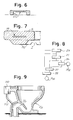
- Fig. 6 shows the profile of an aperture 17 of the type used in the solution in Fig. 4.
- Fig. 7 indicates a seat S in which is incorporated a sensor 19.
- the sensor may be provided by the varnish or paint of the seat itself, which may have a suitable composition, e.g. including metallic components.
- the seat with or without the sensor, has a projecting bead So which acts as a support and seal, with a hollow I for an aperture as at 17 (or that of a subsequent example).
- Fig. 9 shows a solution in which a suction unit 110 - which in this case does not require the presence of a filter - is fitted directly against the rear of the pan Vx, so that suction may be provided directly from apertures such as 1, 5, or 7, while a flexible duct 112 may discharge downstream of the siphon VS of the pan V.
- the pan may have breakable diaphragms for putting into operation the apertures and the discharge of the duct 112.
- the filter 13 or vice versa
- the stale air leaving the unit 11 is directly sent to these pipes through a non-return valve and is thus expelled without the necessity of filtering.
- the air, directly sucked through an aperture advantageously located in the porcelain of the bowl or pan V, may be introduced into the discharge pipe of the water-closet itself, after the siphon, through a non-return valve, in such a way that the whole system may be restricted to the interior of the pan assembly (see Fig. 9).
- the flow of external air into the interior of the bowl must be kept to a minimum in order to reduce the volume of air to be sucked, so that the rotation speed of the motor may be kept to a level such that no arroying noise is caused. Consequently, a seal such as that indicated by 9 or similar, or a special section of the seat S, as indicated by So in Fig. 7, may be present to make the seat fit perfectly on the upper edge of the water-closet pan.
- the detector probe may be inserted directly into the seat and connected to the circuit card by a cable which may for example be located inside the connecting pipes.
- a sensor may also be directly connected to a member which is already present, such as the inductive paint of the seat or other.
- the electrical circuit card 15 for the control and monitoring of the device may be considered as consisting of a number of sections (Fig. 8) including a power supply unit 21, supplied by a transformer 23; a detection sensor 35; a timer 37; and a control unit 39 for the motor 11M of the unit 11.
- the sensor is connected to one or more probes 35A of one or more of the types mentioned above.
- Figs. 10 and following show an embodiment which develops the above mentioned ideas, and in particular those of Figs. 4 to 6.
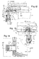
- the rear edge Vo of the pan V has two relatively large holes F, each of which holds, with a large amount of play, the threaded rod 41 for the fixing of the hinged support 43 of the seat S.
- a fin 43A of support 43 engages a rod 45 to which are connected a hinge 47 for seat S and a hinge 49 for cover C.
- Seat S is provided with a continuous upper portion S1 and two lower portions S2 and S3, which are connected to portion S1 and form a substantially continuous bearing on the edge of the pan, except for two housings A for the suction apertures.
- Each support 43 has a cavity 43B which is forwardly open to form the relevant suction aperture.
- Each support 43 forming the aperture 43B is housed in a relevant housing A within seat S (formed by portions S1, S2, S3).
- the supports 43 bear on edge Vo of pan V with the interposition of gaskets which are shaped according to the edges of supports 43, with a forward transverse portion S1A.
- Within cavity 43B of each support 43 there are provided two opposed edges 43D, which engage a cross-piece 53 which can be moved along said edges.
- the threaded rod 41 can be moved along a longitudinal slot in the cross-piece 53.
- each rod 41 can be positioned with a large amount of play along two perpendicular directions, in order to offer a possibility of adaptation to the holes F of the edge Vo of pan V.
- Each sleeve is provided with a respective cross-piece which has respective longitudinal slots.
- the respective rod 41 passes through each slot.
- Ring nuts 59 can be screwed on the sleeves 57 for coupling to flxible ducts 61 for the connection to the suction unit and to the filtration unit, if provided for.
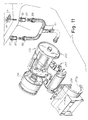
- the suction unit 210 comprises a case 212 wherein the motor with fan 214 is housed.
- 216 denotes a deodorizing filter;
- 212A denotes a cover which closes the case 212.
- a proximity sensor (which can be formed by the paint of seat S) transmits the signals through metallic members 49, 45, 43, 53, 41, 57, a metallic ring 59 of the nut and a metallic conductor combined to duct 61, to the card 218.
Landscapes
- Health & Medical Sciences (AREA)
- Public Health (AREA)
- Epidemiology (AREA)
- Life Sciences & Earth Sciences (AREA)
- Engineering & Computer Science (AREA)
- Hydrology & Water Resources (AREA)
- Water Supply & Treatment (AREA)
- Bidet-Like Cleaning Device And Other Flush Toilet Accessories (AREA)
- Sanitary Device For Flush Toilet (AREA)
- Vehicle Waterproofing, Decoration, And Sanitation Devices (AREA)
Abstract
To eliminate unpleasant odors from the pan of the water-closet, the device comprises means for the suction of unpleasant odors directly from the bowl of the water-closet, particularly through apertures (43B) formed in the seat (S) supports (43), and means for the elimination of the unpleasant odors by means of suction through holes (F) provided for in the pan for the application of said supports.
Description
- The device in question has the object of providing the suction of unpleasant odors directly from the water-closet bowl and the elimination of unpleasant odors through a special filter or by directly conveying them into the water-closet waste pipe itself or to other vent pipes.
- Before they are dispersed into the environment, the unpleasant odors are sucked directly from the water-closet bowl through suction apertures. By means of suitable connections and pipes, the said suction apertures are connected to an external filtration or discharge unit. The device also includes an apparatus for detection of active masses, particularly persons, with at least one sensor, which may be a proximity sensor, either radar, ultrasonic, microwave, infra-red, gravity, or other type; the connecting cable of the various detection systems passes through the interior of the aperture and/or of the pipes. The sensor or group of sensors are such that, when-anyone touches or sits on the seat, the sensor or at least one of the sensors detects the presence of the user and produces a command to the motor of the external unit, which causes a pressure drop in the hollow of the bowl and consequently a suction effect.
- The claims define the invention.
- The invention will be more readily understood by following the description and the attached drawing which shows a practical non-restrictive example of the invention. In the drawing,
- Figs. 1, 2, 3, and 4 show various possible arrangements of the suction apertures;
- Fig. 5 shows a suction and filtration unit;
- Fig. 6 shows a transverse section of an aperture;
- Fig. 7 shows a schematic transverse section of a seat incorporating a sensor;
- Fig. 8 is a block diagram;
- Fig. 9 shows a solution with the fitting on the pan;
- Figs. 10 and 11 show a perspective exploded view of an embodiment of the invention;
- Figs. 12, 13 and 14 show sections taken along line XII-XII in Figs. 13 and 14, line XIII-XIII in Fig. 12 and line XIV- XIV in Fig. 12, respectively.
- In the drawing, 1 in Fig. 1 indicates an
aperture 1 incorporated in the porcelain of the pan V; 3 in Fig. 2 indicates an aperture incorporated in the seat S; in Fig. 3, apertures 5 are interposed between the edge of the bowl or pan V and the seat S; in Fig. 4, apertures 7 are combined with the hinged supports A of the seat S. In all cases, seals such as 9 in Fig. 2 may advantageously be provided between the seat S and the pan V, to facilitate the pressure drop in the pan. - Fig. 5 shows a diagram of a
unit 10 which is connected with suitable ducts to the aperture or apertures. 11 indicates the suction extractor and 13 indicates a filter; a discharge duct may be provided instead of the filter discharging outdoors. 15 indicates an electronic circuit card. - Fig. 6 shows the profile of an
aperture 17 of the type used in the solution in Fig. 4. - Fig. 7 indicates a seat S in which is incorporated a
sensor 19. As an alternative, the sensor may be provided by the varnish or paint of the seat itself, which may have a suitable composition, e.g. including metallic components. - In Fig. 7 the seat, with or without the sensor, has a projecting bead So which acts as a support and seal, with a hollow I for an aperture as at 17 (or that of a subsequent example).
- Fig. 9 shows a solution in which a suction unit 110 - which in this case does not require the presence of a filter - is fitted directly against the rear of the pan Vx, so that suction may be provided directly from apertures such as 1, 5, or 7, while a
flexible duct 112 may discharge downstream of the siphon VS of the pan V. The pan may have breakable diaphragms for putting into operation the apertures and the discharge of theduct 112. - The air from the bowl or pan V, sucked through the suction apertures and the connecting pipes, is passed through the unit 11 to the filter 13 (or vice versa) where it is purified by means of active filters and, after being lightly perfumed, is returned to the environment. Where possible, in the presence of accessible vent pipes or of the discharge pipe of the siphon of the pan, the stale air leaving the unit 11 is directly sent to these pipes through a non-return valve and is thus expelled without the necessity of filtering. In an alternative solution the air, directly sucked through an aperture advantageously located in the porcelain of the bowl or pan V, may be introduced into the discharge pipe of the water-closet itself, after the siphon, through a non-return valve, in such a way that the whole system may be restricted to the interior of the pan assembly (see Fig. 9).
- Obviously, the flow of external air into the interior of the bowl must be kept to a minimum in order to reduce the volume of air to be sucked, so that the rotation speed of the motor may be kept to a level such that no arroying noise is caused. Consequently, a seal such as that indicated by 9 or similar, or a special section of the seat S, as indicated by So in Fig. 7, may be present to make the seat fit perfectly on the upper edge of the water-closet pan.
- For detection by a proximity sensor, the detector probe may be inserted directly into the seat and connected to the circuit card by a cable which may for example be located inside the connecting pipes. A sensor may also be directly connected to a member which is already present, such as the inductive paint of the seat or other.
- The
electrical circuit card 15 for the control and monitoring of the device may be considered as consisting of a number of sections (Fig. 8) including apower supply unit 21, supplied by atransformer 23; adetection sensor 35; atimer 37; and a control unit 39 for themotor 11M of the unit 11. The sensor is connected to one ormore probes 35A of one or more of the types mentioned above. - Figs. 10 and following show an embodiment which develops the above mentioned ideas, and in particular those of Figs. 4 to 6.
- It is known that the rear edge Vo of the pan V has two relatively large holes F, each of which holds, with a large amount of play, the threaded
rod 41 for the fixing of thehinged support 43 of the seat S. Afin 43A ofsupport 43 engages arod 45 to which are connected ahinge 47 for seat S and ahinge 49 for cover C. Seat S is provided with a continuous upper portion S1 and two lower portions S2 and S3, which are connected to portion S1 and form a substantially continuous bearing on the edge of the pan, except for two housings A for the suction apertures. Eachsupport 43 has a cavity 43B which is forwardly open to form the relevant suction aperture. Eachsupport 43 forming the aperture 43B is housed in a relevant housing A within seat S (formed by portions S1, S2, S3). The supports 43 bear on edge Vo of pan V with the interposition of gaskets which are shaped according to the edges ofsupports 43, with a forward transverse portion S1A. Within cavity 43B of eachsupport 43 there are provided twoopposed edges 43D, which engage across-piece 53 which can be moved along said edges. The threadedrod 41 can be moved along a longitudinal slot in thecross-piece 53. Thus, eachrod 41 can be positioned with a large amount of play along two perpendicular directions, in order to offer a possibility of adaptation to the holes F of the edge Vo of pan V. - Under edge Vo the
gaskets 55 of twosleeves 57 are applied. Each sleeve is provided with a respective cross-piece which has respective longitudinal slots. Therespective rod 41 passes through each slot.Ring nuts 59 can be screwed on thesleeves 57 for coupling toflxible ducts 61 for the connection to the suction unit and to the filtration unit, if provided for. - The
suction unit 210 comprises acase 212 wherein the motor withfan 214 is housed. 216 denotes a deodorizing filter; 212A denotes a cover which closes thecase 212. In thecase 212 there is housed also anelectronic card 218. A proximity sensor (which can be formed by the paint of seat S) transmits the signals throughmetallic members metallic ring 59 of the nut and a metallic conductor combined toduct 61, to thecard 218.
Claims (13)
1) A device for the elimination of unpleasant odors from the pans of water-closets, comprising means for the suction of the unpleasant odors directly from the water-closet bowl, and means for the elimination of the unpleasant odors through a special filter or by conveying them to the outside.
2) The device as in the preceding claim, comprising means for direct conveying into the water-closet waste pipe.
3) The device as in claim 1 or 2, in which, to prevent the dispersion of the unpleasant odors in the environment, suction apertures are provided and are disposed for suction from the interior of the bowl or pan of the water-closet, this interior being suitably bounded by seals or other devices between the seat and the edge of the pan.
4) The device as in one or more of claims 1 through 3, in which the aperture or apertures are provided directly in the porcelain of the pan.
5) The device as in one or more of claims 1 through 3, in which the aperture or apertures are provided inside the seat.
6) The device as in one or more of claims 1 through 3, in which the aperture or apertures are located so that they rest on the upper edge of the pan, between the pan and the seat.
7) The device as in one or more of claims 1 through 3, in which the aperture or apertures are integral in the hinged supports of the said seat.
8) The device as in claim 7, in which the apertures are formed with hollow elements which act in combination with the surface of the pan.
9) The device as in claims 7 and 8, in which suction is provided through the attachment holes of the supports.
10) The device as in claim 9, in which each of the threaded rods provided for mounting the supports is engaged along a slot of a cross-piece which is slidably mounted in the hollow element and is slidable along a slot in a sleeve placed underneath and provided for connection with a suction duct.
11) The device as in one or more of the preceding claims which includes an external filtration or discharge unit.
12) The device as in one or more of the preceding claims which also includes an apparatus for detection of active masses, particularly persons, with one or more sensors, which may be selected from proximity sensors of the radar, ultrasonic, micro-wave, infra-red, gravity or other type.
13) The device as in claim 12, wherein a sensor is provided by an inductive paint of the seat or cover.
Applications Claiming Priority (2)
| Application Number | Priority Date | Filing Date | Title |
|---|---|---|---|
| IT91FI000025A ITFI910025A1 (en) | 1991-01-31 | 1991-01-31 | DEVICE FOR THE ELIMINATION OF BAD BATHROOM ODORS DIRECTLY FROM THE TOILET. |
| ITFI910025 | 1991-12-31 |
Publications (1)
| Publication Number | Publication Date |
|---|---|
| EP0550388A1 true EP0550388A1 (en) | 1993-07-07 |
Family
ID=11349458
Family Applications (1)
| Application Number | Title | Priority Date | Filing Date |
|---|---|---|---|
| EP92830025A Withdrawn EP0550388A1 (en) | 1991-01-31 | 1992-01-24 | Device for the elimination of unpleasant bathroom odors directly from the water-closet |
Country Status (4)
| Country | Link |
|---|---|
| EP (1) | EP0550388A1 (en) |
| AU (1) | AU1053592A (en) |
| CA (1) | CA2059744A1 (en) |
| IT (1) | ITFI910025A1 (en) |
Cited By (9)
| Publication number | Priority date | Publication date | Assignee | Title |
|---|---|---|---|---|
| FR2709318A1 (en) * | 1993-08-23 | 1995-03-03 | Datcharry Adalgisa | Device for aspiration and removal of odours and gases from a lavatory bowl |
| WO2000061883A1 (en) * | 1999-04-12 | 2000-10-19 | Kohler Company | Devices and methods for toilet ventilation using a radar sensor |
| WO2000077312A1 (en) * | 1999-06-16 | 2000-12-21 | Rocco Sagarese | Toilet supplied with a fecal gas extractor |
| FR2806113A1 (en) * | 2000-03-08 | 2001-09-14 | Santos Jose Manuel Pinheiro | Lavatory seat has holes in underside linked through inner channel to air extractor duct |
| GB2379463A (en) * | 2001-09-06 | 2003-03-12 | John Kennedy Fletcher | Toilet bowl ventilator |
| GB2379460A (en) * | 2001-09-06 | 2003-03-12 | John Kennedy Fletcher | Toilet bowl ventilator |
| GB2379461A (en) * | 2001-09-06 | 2003-03-12 | John Kennedy Fletcher | Toilet bowl ventilator |
| NL1033945C2 (en) * | 2006-11-03 | 2008-05-08 | Wannie Margreet Wiegman Rootje | Toilet bowl module with air extractor unit, has height and width chosen to allow it to be retrofitted between top side of bowl and underside of toilet seat |
| WO2012032275A1 (en) * | 2010-09-09 | 2012-03-15 | Ramez Ghadri | Toilet bowl equipment with scented-air diffuser |
Families Citing this family (1)
| Publication number | Priority date | Publication date | Assignee | Title |
|---|---|---|---|---|
| USD402747S (en) | 1996-01-31 | 1998-12-15 | Yeatts Jr Robert | Combined toilet seat air vent and exhaust system |
Citations (7)
| Publication number | Priority date | Publication date | Assignee | Title |
|---|---|---|---|---|
| US2527110A (en) * | 1946-01-15 | 1950-10-24 | Wheeler Dona | Suction head |
| GB1134095A (en) * | 1964-11-09 | 1968-11-20 | Natalio Levitt | Ventilating apparatus for water closets and like places |
| FR2135812A5 (en) * | 1971-04-29 | 1972-12-22 | Minguzzi Pier | |
| US3849808A (en) * | 1973-06-21 | 1974-11-26 | C Olson | Toilet exhaust means |
| US3887949A (en) * | 1973-08-03 | 1975-06-10 | John S Osmond | Ventilated seating for a water closet |
| GB2143872A (en) * | 1983-07-26 | 1985-02-20 | John Headley Billing | Ventilating W.C. pans |
| US4620329A (en) * | 1985-06-17 | 1986-11-04 | John Wix | Ventilated toilet seat |
-
1991
- 1991-01-31 IT IT91FI000025A patent/ITFI910025A1/en not_active Application Discontinuation
-
1992
- 1992-01-22 CA CA002059744A patent/CA2059744A1/en not_active Abandoned
- 1992-01-24 EP EP92830025A patent/EP0550388A1/en not_active Withdrawn
- 1992-01-30 AU AU10535/92A patent/AU1053592A/en not_active Abandoned
Patent Citations (7)
| Publication number | Priority date | Publication date | Assignee | Title |
|---|---|---|---|---|
| US2527110A (en) * | 1946-01-15 | 1950-10-24 | Wheeler Dona | Suction head |
| GB1134095A (en) * | 1964-11-09 | 1968-11-20 | Natalio Levitt | Ventilating apparatus for water closets and like places |
| FR2135812A5 (en) * | 1971-04-29 | 1972-12-22 | Minguzzi Pier | |
| US3849808A (en) * | 1973-06-21 | 1974-11-26 | C Olson | Toilet exhaust means |
| US3887949A (en) * | 1973-08-03 | 1975-06-10 | John S Osmond | Ventilated seating for a water closet |
| GB2143872A (en) * | 1983-07-26 | 1985-02-20 | John Headley Billing | Ventilating W.C. pans |
| US4620329A (en) * | 1985-06-17 | 1986-11-04 | John Wix | Ventilated toilet seat |
Cited By (13)
| Publication number | Priority date | Publication date | Assignee | Title |
|---|---|---|---|---|
| FR2709318A1 (en) * | 1993-08-23 | 1995-03-03 | Datcharry Adalgisa | Device for aspiration and removal of odours and gases from a lavatory bowl |
| AU774375B2 (en) * | 1999-04-12 | 2004-06-24 | Kohler Company | Devices and methods for toilet ventilation using a radar sensor |
| US6279173B1 (en) * | 1999-04-12 | 2001-08-28 | D2M, Inc. | Devices and methods for toilet ventilation using a radar sensor |
| JP2002541369A (en) * | 1999-04-12 | 2002-12-03 | コーラー、カンパニー | Devices and methods for toilet ventilation using radar sensors |
| WO2000061883A1 (en) * | 1999-04-12 | 2000-10-19 | Kohler Company | Devices and methods for toilet ventilation using a radar sensor |
| WO2000077312A1 (en) * | 1999-06-16 | 2000-12-21 | Rocco Sagarese | Toilet supplied with a fecal gas extractor |
| FR2806113A1 (en) * | 2000-03-08 | 2001-09-14 | Santos Jose Manuel Pinheiro | Lavatory seat has holes in underside linked through inner channel to air extractor duct |
| GB2379463A (en) * | 2001-09-06 | 2003-03-12 | John Kennedy Fletcher | Toilet bowl ventilator |
| GB2379460A (en) * | 2001-09-06 | 2003-03-12 | John Kennedy Fletcher | Toilet bowl ventilator |
| GB2379461A (en) * | 2001-09-06 | 2003-03-12 | John Kennedy Fletcher | Toilet bowl ventilator |
| NL1033945C2 (en) * | 2006-11-03 | 2008-05-08 | Wannie Margreet Wiegman Rootje | Toilet bowl module with air extractor unit, has height and width chosen to allow it to be retrofitted between top side of bowl and underside of toilet seat |
| WO2012032275A1 (en) * | 2010-09-09 | 2012-03-15 | Ramez Ghadri | Toilet bowl equipment with scented-air diffuser |
| FR2964673A1 (en) * | 2010-09-09 | 2012-03-16 | Ramez Ghadri | PERFUMED AIR DIFFUSER TOILET WC TOILET |
Also Published As
| Publication number | Publication date |
|---|---|
| ITFI910025A1 (en) | 1992-07-31 |
| AU1053592A (en) | 1992-08-06 |
| CA2059744A1 (en) | 1992-08-01 |
| ITFI910025A0 (en) | 1991-01-31 |
Similar Documents
| Publication | Publication Date | Title |
|---|---|---|
| EP0550388A1 (en) | Device for the elimination of unpleasant bathroom odors directly from the water-closet | |
| US5199111A (en) | Toilet odor removing apparatus | |
| US3585651A (en) | Odor remover for toilets | |
| US6393635B2 (en) | Galley waste disposal system and method | |
| US5054130A (en) | Toilet deodorizing device | |
| US3902203A (en) | Toilet stool ventilating means | |
| US5251340A (en) | Flush toilet with an automatic sterilizing device | |
| CA2368941A1 (en) | Devices and methods for toilet ventilation using a radar sensor | |
| US5452481A (en) | Portable ventilation system | |
| US3953901A (en) | Toilet stool ventilating means | |
| US4893359A (en) | Vented toilet bowl | |
| GB2136030A (en) | Ventilating water closet pans | |
| EP0994676A2 (en) | Apparatus for and method of cleaning hands | |
| GB2178456A (en) | Odour extractor apparatus for use with lavatories | |
| US5857222A (en) | Removal of odors from toilets | |
| US5105479A (en) | Simple low cost means for venting a water closet | |
| EP0201768A3 (en) | Installation unit for sanitary apparatuses | |
| EP1492928B1 (en) | Stench-free toilet system | |
| EP1621691A2 (en) | Device and method for deodorising toilets and toilets equipped with the device | |
| US5351344A (en) | Fluid evacuation system | |
| GB2330152A (en) | Toilet bowl ventilation | |
| WO1988006661A1 (en) | Improved ventilating toilet | |
| US7376982B1 (en) | Toilet bowl venting apparatus | |
| KR20020086205A (en) | Externally vented modular toilet seat | |
| GB2196355A (en) | Extractor for water closets |
Legal Events
| Date | Code | Title | Description |
|---|---|---|---|
| PUAI | Public reference made under article 153(3) epc to a published international application that has entered the european phase |
Free format text: ORIGINAL CODE: 0009012 |
|
| AK | Designated contracting states |
Kind code of ref document: A1 Designated state(s): AT BE CH DE DK ES FR GB GR IT LI LU MC NL PT SE |
|
| 18D | Application deemed to be withdrawn |
Effective date: 19940108 |