EP0550356B1 - Digital PID control - Google Patents
Digital PID control Download PDFInfo
- Publication number
- EP0550356B1 EP0550356B1 EP92420478A EP92420478A EP0550356B1 EP 0550356 B1 EP0550356 B1 EP 0550356B1 EP 92420478 A EP92420478 A EP 92420478A EP 92420478 A EP92420478 A EP 92420478A EP 0550356 B1 EP0550356 B1 EP 0550356B1
- Authority
- EP
- European Patent Office
- Prior art keywords
- derivative
- equation
- motor
- component
- torque
- Prior art date
- Legal status (The legal status is an assumption and is not a legal conclusion. Google has not performed a legal analysis and makes no representation as to the accuracy of the status listed.)
- Expired - Lifetime
Links
- 238000012937 correction Methods 0.000 claims description 22
- 238000000034 method Methods 0.000 claims description 16
- 230000004048 modification Effects 0.000 claims description 3
- 238000012986 modification Methods 0.000 claims description 3
- 230000001105 regulatory effect Effects 0.000 claims description 2
- 230000008901 benefit Effects 0.000 description 6
- 230000001133 acceleration Effects 0.000 description 5
- 230000009471 action Effects 0.000 description 4
- 230000000694 effects Effects 0.000 description 3
- BTCSSZJGUNDROE-UHFFFAOYSA-N gamma-aminobutyric acid Chemical compound NCCCC(O)=O BTCSSZJGUNDROE-UHFFFAOYSA-N 0.000 description 3
- 230000010355 oscillation Effects 0.000 description 3
- 238000012545 processing Methods 0.000 description 3
- 230000001276 controlling effect Effects 0.000 description 2
- 230000003247 decreasing effect Effects 0.000 description 2
- 230000009467 reduction Effects 0.000 description 2
- 238000005070 sampling Methods 0.000 description 2
- 238000004804 winding Methods 0.000 description 2
- 238000013016 damping Methods 0.000 description 1
- 238000011161 development Methods 0.000 description 1
- 230000003467 diminishing effect Effects 0.000 description 1
- 230000006872 improvement Effects 0.000 description 1
- 238000005259 measurement Methods 0.000 description 1
- 230000003071 parasitic effect Effects 0.000 description 1
- 230000004044 response Effects 0.000 description 1
- 238000012360 testing method Methods 0.000 description 1
- 230000009466 transformation Effects 0.000 description 1
- 230000017105 transposition Effects 0.000 description 1
Images


Classifications
-
- G—PHYSICS
- G05—CONTROLLING; REGULATING
- G05B—CONTROL OR REGULATING SYSTEMS IN GENERAL; FUNCTIONAL ELEMENTS OF SUCH SYSTEMS; MONITORING OR TESTING ARRANGEMENTS FOR SUCH SYSTEMS OR ELEMENTS
- G05B11/00—Automatic controllers
- G05B11/01—Automatic controllers electric
- G05B11/36—Automatic controllers electric with provision for obtaining particular characteristics, e.g. proportional, integral, differential
- G05B11/42—Automatic controllers electric with provision for obtaining particular characteristics, e.g. proportional, integral, differential for obtaining a characteristic which is both proportional and time-dependent, e.g. P. I., P. I. D.
-
- B—PERFORMING OPERATIONS; TRANSPORTING
- B65—CONVEYING; PACKING; STORING; HANDLING THIN OR FILAMENTARY MATERIAL
- B65H—HANDLING THIN OR FILAMENTARY MATERIAL, e.g. SHEETS, WEBS, CABLES
- B65H23/00—Registering, tensioning, smoothing or guiding webs
- B65H23/04—Registering, tensioning, smoothing or guiding webs longitudinally
- B65H23/18—Registering, tensioning, smoothing or guiding webs longitudinally by controlling or regulating the web-advancing mechanism, e.g. mechanism acting on the running web
- B65H23/182—Registering, tensioning, smoothing or guiding webs longitudinally by controlling or regulating the web-advancing mechanism, e.g. mechanism acting on the running web in unwinding mechanisms or in connection with unwinding operations
-
- G—PHYSICS
- G05—CONTROLLING; REGULATING
- G05D—SYSTEMS FOR CONTROLLING OR REGULATING NON-ELECTRIC VARIABLES
- G05D15/00—Control of mechanical force or stress; Control of mechanical pressure
- G05D15/01—Control of mechanical force or stress; Control of mechanical pressure characterised by the use of electric means
Definitions
- the present invention relates to control and more particularly to an improvement to closed loop control systems.
- control systems generally used comprise control loops, optionally in cascades, to make it possible to regulate an intermediate quantity on which the influence of the perturbations shows itself more rapidly than on the principal quantity controlled.
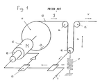
- Fig 1 shows a device of the prior art making it possible to regulate the movement of a strip 10 wound on a roll 11 driven by a motor 12.
- the motor 12 drives the roll 11 in the direction of the arrow 13 so as to reel out the strip 10 at a speed dy/dt.
- the strip 10 supplies a machine (not shown) at a feed speed dx/dt. So as to be able to control the speed of rotation of the motor 12 as a function of the feed speed dx/dt of the strip into the machine (not shown), it is necessary to measure the variation in speed between the feed into the machine and the speed at which the strip is reeled out. In order to do this, three idler rollers 14, 15, 16 are used, enabling the direction of the strip to be changed.
- the roller 16 is drawn back by a spring 17, a weight, a jack, or any other similar component.
- the position of the roller 16 is a function of the difference between the feed speed dx/dt and the reeling-out speed dy/dt. Normally the speed of rotation ⁇ of the motor 12 is measured by means of a tachometer 18.
- the speed at which the reel should rotate is derived from the position of the roller 16. It is compared at 19 with the signals coming from the tachometer so as to derive from this an error signal which is sent to the motor 12.
- PID devices with proportional, integral and derivative action well known in the art are used, which make it possible to obtain actions giving good stability whilst diminishing the transitory phases.
- the setting of the parameters of these PID devices is long and tedious since it is carried out by successive approximations and the actions on one of the parameters generally entail modification of the other parameters.
- US 3,770,946 describes a method for automatic control wherein a digital computer is used as a controller. In said method a control error is produced and sent to three separate circuits for computation of proportional, reset and rate components for applying respective coefficients K1, K2, K3. It is stated that coefficients could be modified. However, the document does not provide any hint how said coefficients are modified and the method only provides means to prevent an immediate proportional and rate response when the set point and/or coefficients are changed.
- DE-A-3 418 969 describes a device wherein a second derivative control is used.
- said document describes a cascade control device and the second derivative is only to adapt the speed of reaction of the control device. Nowhere an automatic regulation of the coefficients is described.
- the object of the invention is to provide a control method in which the settings are obtained systematically and without any empirical procedure, whatever the machine, ie independently of any small variations in friction or inertia in the components, either with respect to the theoretical value, or between two identical machines.
- the object is achieved by means of a method according to claim 1 in which:
- the motor is provided with a torque which depends on the error measured.
- Routh's criterion This condition is already known by the name of Routh's criterion but it is not sufficient to eliminate the transitory phase oscillations completely.
- the advantages inherent in the invention in having introduced the factor i can already be seen. In fact, this condition is independent of this factor.
- Equation (10) The real roots of equation (10) are called z1, z2 and z3 where z3 ⁇ z2 ⁇ z1 ⁇ 0.
- Equation (10) gives a continuous third order curve between - ⁇ and + ⁇ . Equation (10) therefore permits at least one real root.
- Kdi 4 Kpi 2 ie: Kd 2 > 4p
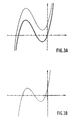
- Fig 3C The curve provided by equation (10) can be considered to be the sum of a first function z3 and a second function Kdi zo + Kpi zo + Ki3.
- Fig 3C shows in a continuous line (single and double) the two functions and in a broken line their sum which is the left- hand side of equation (10).
- condition (12) can be written: d 2 > 4p
- the values of p and d should be within the non-hatched area in Fig 3D.
- these two conditions are independent of the value of the correction factor i.
- This factor was introduced into equation (5) in such a way that it does not interfere with the stability conditions. It therefore makes it possible to adjust the "reaction" of the system as a function of time and, during the transitory phases, the equilibrium position is achieved more quickly as the value of i becomes greater.
- i can be a variable factor, controllable by any external parameters to suit the different requirements which can be conceived.
- K was made equal to k / (a + J ⁇ ) and K ⁇ 1, where k is the general gain, ⁇ and ⁇ are constants and J the inertia of the system. It is well known that in order to avoid large accelerations which would impair the stability of the system, it is necessary to work with a moderate motor torque and use a low general gain k. When digital systems are used, idle times occur because the signals are sampled. This phenomenon causes errors. It has been found from experience that digital control of these systems could be achieved only if 1 ⁇ K ⁇ 2. This therefore gives k ⁇ a + J ⁇ and when J ⁇ is constant a zero value can be chosen for the factor a, which takes us back to the known art in which equation (5) does not involve the second derivative.
- K varies between a minimum value and a maximum value.
- J ⁇ varies between (J ⁇ )min and (J ⁇ )Max.
- Equation (7) has, up to now, been considered without the right-hand side.
- J ⁇ m/ ⁇ + ⁇ je/ ⁇ 2 + ⁇ jm with m given by equation (18).
- Cd ⁇ (Cm - jm ⁇ ') in which jm represents the inertia of the motor carrying the drive pulley of radius Rm.
- the invention can be dealt with in a well-known digital manner.
- Co the maximum torque exerted by the motor when the digital/analogue transmitter controlling the motor amplifier is at its maximum
- Eo the maximum number of possible points which can be accepted by the transmitter
- N the sampling frequency N must be sufficiently large.
- N 50.
- condition (50) is more difficult to achieve.
- this condition is not achieved, it is nevertheless possible to use the invention by cancelling the value of the factor a and by using the value of the second derivative for automatically adjusting the factor k.
- the procedure is started with k N J ⁇ and the ideal gain k is sought by writing the condition with a constant i.
- the gain is decreased, verifying the following condition: If z" > z"max then ⁇ ⁇ Z > Zo N 2 z'' max .
- the advantage of the invention lies essentially in the fact that stability conditions (14) and (15) were discovered which up until then were unknown and that the use of an additional parameter independent of the stability conditions makes it possible to mitigate the approximations necessary for the calculation of the system.
Landscapes
- Physics & Mathematics (AREA)
- General Physics & Mathematics (AREA)
- Engineering & Computer Science (AREA)
- Automation & Control Theory (AREA)
- Feedback Control In General (AREA)
- Control Of Position Or Direction (AREA)
Description
- The present invention relates to control and more particularly to an improvement to closed loop control systems.
- The control systems generally used comprise control loops, optionally in cascades, to make it possible to regulate an intermediate quantity on which the influence of the perturbations shows itself more rapidly than on the principal quantity controlled.
- It is well known that positioning systems having several loops in cascades can be used.
- Fig 1 shows a device of the prior art making it possible to regulate the movement of a
strip 10 wound on aroll 11 driven by amotor 12. Themotor 12 drives theroll 11 in the direction of thearrow 13 so as to reel out thestrip 10 at a speed dy/dt. Thestrip 10 supplies a machine (not shown) at a feed speed dx/dt. So as to be able to control the speed of rotation of themotor 12 as a function of the feed speed dx/dt of the strip into the machine (not shown), it is necessary to measure the variation in speed between the feed into the machine and the speed at which the strip is reeled out. In order to do this, threeidler rollers roller 16 is drawn back by aspring 17, a weight, a jack, or any other similar component. The position of theroller 16 is a function of the difference between the feed speed dx/dt and the reeling-out speed dy/dt. Normally the speed of rotation Ω of themotor 12 is measured by means of atachometer 18. - The speed at which the reel should rotate is derived from the position of the
roller 16. It is compared at 19 with the signals coming from the tachometer so as to derive from this an error signal which is sent to themotor 12. Advantageously, PID devices with proportional, integral and derivative action well known in the art are used, which make it possible to obtain actions giving good stability whilst diminishing the transitory phases. However, the setting of the parameters of these PID devices is long and tedious since it is carried out by successive approximations and the actions on one of the parameters generally entail modification of the other parameters. - These control chains are generally of analog type. However, the arrival on the market of digital PID devices, made possible by the current stage of development of electronics, now allows digital processing by means of analogue/digital converters.
- US 3,770,946 describes a method for automatic control wherein a digital computer is used as a controller. In said method a control error is produced and sent to three separate circuits for computation of proportional, reset and rate components for applying respective coefficients K₁, K₂, K₃. It is stated that coefficients could be modified. However, the document does not provide any hint how said coefficients are modified and the method only provides means to prevent an immediate proportional and rate response when the set point and/or coefficients are changed.
- DE-A-3 418 969 describes a device wherein a second derivative control is used. However, said document describes a cascade control device and the second derivative is only to adapt the speed of reaction of the control device. Nowhere an automatic regulation of the coefficients is described.
- The object of the invention is to provide a control method in which the settings are obtained systematically and without any empirical procedure, whatever the machine, ie independently of any small variations in friction or inertia in the components, either with respect to the theoretical value, or between two identical machines. The object is achieved by means of a method according to claim 1 in which:
- a) the position of a first component to be regulated, with respect to a second component, said first component moving under the influence of a torque Cm or force F, is defined digitally,
- b) the data corresponding to said position is processed in order to obtain the first derivative and the integral of said position, and
- c) the torque Cm or force F to be applied to this first component is determined as a function of the solutions to an equation depending on the first derivative, the integral and the position data,
method characterised in that: - d) the data is processed to obtain the second derivative of the position measured;
- e)the equation is

- f) an automatic correction of the correction factors to be applied to the integral, the first derivative and the position data is carried out through modifications of i and/or k in order to calculate, respectively, the torque or force to be applied to the first component.
- In the accompanying drawing, given by way of example:
- Fig 1 shows diagrammatically a control circuit of the prior art;
- Fig 2 shows diagrammatically a control circuit according to the invention for the same application;
- Figs 3A-3D show graphs enabling the conditions required for implementing the invention to be understood better;
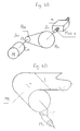
- Figs 4A and 4B show diagrammatically the automatic centring of a width of material by means of a device according to the invention.
- In order to understand the invention better, the theory will first of all be dealt with. It is well known that when it is desired to regulate a "positioning" system in which a component with inertia is moving, it is possible to act only through a force which produces an action on the second derivative.
- In the prior art, when it was desired to regulate a mechanical system driven by a motor, the difference in position between the actual position and the theoretical position was measured so as to determine from this a speed of rotation of the motor (the reference) which was compared with the actual speed in order to provide a correction signal. This mechanical system can be studied in the following manner.
- Let J be the inertia of the mechanical system referred to the motor shaft, Ω the angular velocity of the motor, Cm the torque delivered by the motor and Cf the torque due to parasitic friction. It is well known that:

- If the movement of the part of the mechanical system, a movement providing the correction of an error, is termed y, and the ratio between Ω and the speed of this movement is termed α, this gives the relationship


- If x is the error at the input and z the error measured at the output, the relationship existing between x, y and z is of the type:

- For control purposes, the motor is provided with a torque which depends on the error measured. The control systems of the prior art showed that there was a certain advantage for the torque to depend not only on the value of the measured error u but also on its derivative and its integral (PID):

- According to the invention, the velocity difference is no longer measured and the motor torque thus depends on the second derivative of the error z".

- k is the general gain;
- (d.i) is the correction factor applied to the first derivative;
- (p.i) is the correction factor applied to the proportional reaction;
- a is the correction factor applied to the acceleration;
- i³ is an integral correction factor.
- The advantage of i will be seen later. In the prior art this factor was equal to 1 and did not appear in the equations.
- Differentiating relationship (4) twice gives

- Substituting relationships (5) and (6) in relationship (3) gives:

- Putting K = k/(a + Jατ) and differentiating gives:


- It is well known that if damping is desired, the real parts of z1, z2 and z3 must be negative. It can easily be demonstrated that this condition is fulfilled when:


- This condition is already known by the name of Routh's criterion but it is not sufficient to eliminate the transitory phase oscillations completely. The advantages inherent in the invention in having introduced the factor i can already be seen. In fact, this condition is independent of this factor.
- If it is desired that the solutions to equation (8) should have no oscillation, it is necessary and sufficient for z1, z2 and z3 in equation (9) to be real and negative.
- If one of the solutions is made equal to ezot, by substituting its values in equation (8) and dividing by ezot, this gives:

- The real roots of equation (10) are called z1, z2 and z3 where z3 ≤ z2 ≤ z1 ≤ 0.
- It will be recalled that the factors K, d, p and i are positive. Let us determine the conditions linking the factors so as to have real negative roots.
- It will be noted that the value of the left-hand side of equation (10) gives a continuous third order curve between -∞ and +∞. Equation (10) therefore permits at least one real root. The value for z = 0 is equal to Ki³ ie positive because of the conditions already mentioned with regard to the factors. If the curve is displaced by the amount -K i³, a curve is obtained similar to the one shown in a double line in Fig 3A, and equation (10) becomes:


- When condition (12) is fulfilled, the z3 solution is real and negative whatever the positive value of Ki³.
- Let us now consider Fig 3C. The curve provided by equation (10) can be considered to be the sum of a first function z3 and a second function Kdi zo + Kpi zo + Ki³. Fig 3C shows in a continuous line (single and double) the two functions and in a broken line their sum which is the left- hand side of equation (10).
- If we call the roots of the equation

- For equation (13) to have real solutions, it suffices that:

- When conditions (12) and (14) are satisfied, real negative roots z1 and z3 are obtained and therefore z2, which is between z1 and z3, is also real and negative.
- If we take K ≥ 1, condition (12) can be written:

- It can be demonstrated that if conditions (14) and (12) exist, they necessarily entail Kpd > 1.
- Fig 3D shows the curve A of equation p = d/4 and the curve B of equation d = p/4, which are the conditions (14) and (15). In order to avoid oscillations, it suffices that the values of p and d should be within the non-hatched area in Fig 3D. It will be noted that these two conditions are independent of the value of the correction factor i. This factor was introduced into equation (5) in such a way that it does not interfere with the stability conditions. It therefore makes it possible to adjust the "reaction" of the system as a function of time and, during the transitory phases, the equilibrium position is achieved more quickly as the value of i becomes greater. In addition, i can be a variable factor, controllable by any external parameters to suit the different requirements which can be conceived. For example, in the case of an umvinding, if it is desired to limit the acceleration of the moving cylinder so as not to create high excess tension in the web, i can be automatically adjusted by writing the condition: if z" > z"max then i = i - δi or, even better, i = qi where q < 1.
- As indicated previously, K was made equal to k / (a + Jατ) and K ≤ 1, where k is the general gain, α and τ are constants and J the inertia of the system. It is well known that in order to avoid large accelerations which would impair the stability of the system, it is necessary to work with a moderate motor torque and use a low general gain k. When digital systems are used, idle times occur because the signals are sampled. This phenomenon causes errors. It has been found from experience that digital control of these systems could be achieved only if 1 ≤ K ≤ 2. This therefore gives k≈a + Jατ and when Jατ is constant a zero value can be chosen for the factor a, which takes us back to the known art in which equation (5) does not involve the second derivative. However, when the inertia varies during operation, K varies between a minimum value and a maximum value. Jατ varies between (Jατ)min and (Jατ)Max.
Putting k = a + (Jατ)Max and a = ao (Jατ)Max gives:
K = 1 when Jατ is equal to its maximum value and
K = ( ao + 1 ) / ( ao + (Jατ)min / (Jατ)Max )
when Jατ is minimum. - If ao is made large, the variation in K can be made small. Putting ao = 2 gives
1 ≤ K < 1.5 and ao = 5 gives 1 ≤ K < 1.2. - Equation (7) has, up to now, been considered without the right-hand side. The solutions to equation (7) with the right-hand side are in the form of the solutions of the equation without the right-hand side plus a special solution, ie:

- It can be seen therefore that the introduction of a correction proportional to the second derivative of the difference z 1) attenuates the effect of the variation in the inertia; 2) attenuates the effect of the perturbation due to the input error x; 3) allows an error in the determination of J.
- The latter effect provides the practical possibility of making an approximate calculation of the value of the inertia and determining an order of magnitude of the factors and parameters for implementing the invention.
- It will now be seen how the invention can be used for the automatic centring of a width of material. As can be seen from Fig 4B, the movement z of the width of material is given by the relationship:


- If the density of the reel is ρ, the radius of the reel R and the width of the material l, this gives:

- Consider the motor torque Cm which has to be controlled in order to move a mass m. In the example shown in Fig 4A, Cm is in the form

- If the inertia of the motor fitted with the pulley of radius Rmotor is jm, then:

- If the inertia of the rotating assembly consisting of the screw with pitch s and the associated pulley with radius Rscrew is called je, then:


- The torque Cml utilised to move the mass m is calculated as follows. One rotation of the screw moves the mass m by the quantity s. One rotation of the motor moves this mass by the quantity s/µ. If the angular velocity of the motor is called Ω, this gives:

- Comparing equation (23) with equation (2) gives:

- The force F used for the movement of the mass is given by the equation:


- The motor torque Cm1 may then be written as:


- The total motor torque is therefore

- The value of Jατ is therefore:

- As indicated above, it can be seen therefore that an approximate value of the inertia referred back to the motor can be calculated and that introducing the second derivative of the difference makes it possible to calculate approximate values which can be used for the subsequent automatic control.
- The advantages of a and i exist only because the other coefficients k, p and d have been previously determined. (In fact, if the values of p and d are arbitrary or are adjusted empirically during the tests, the settings thus obtained will be suitable only for the values of i and a utilised at the time of these settings and will, therefore, no longer have their independence and the advantages mentioned.) The predetermination of the values of k, d and p is possible only because of the demonstration of the two stability conditions (14) and (15) and the complete digital processing which alone makes it possible to be certain of the values introduced into the system.
- Consider another application of the invention with reference to Fig 2; the unwinding or winding of a film from or onto a core.
- As can be seen in Fig 2, the movement z of the idler roller is given by the equation

- Comparing this equation with equation (4) gives:

- Designating the reduction ratio of the pulley drive system µ, where µ = Rb/Rm, and the angular velocity of the motor Ω, it is possible to write:

- Comparing this equation with equation (2) gives

- To simplify the mathematics, it is assumed that the idler rollers are identical. Let m be the mass of each roller, jc their respective inertias, r their radius and 2T the restoring force exerted on the intermediate roller used to keep the film under tension. The tension Ty assisting the motor can be written in the form:

- The torque Cd available to drive the reel can be written:

- The torque enabling the film to be moved is represented by Ty R + Cd. This therefore gives:


- Differentiating equation (31) gives:

- We therefore obtain from equation (36) and the differentiated equation (32)


- As indicated above, it can therefore be seen, here again, that it is possible to estimate an approximate value of the inertia, referred back to the motor, which enables the invention to be implemented.
- Once an approximation of the inertia referred back to the motor has been determined, the invention can be dealt with in a well-known digital manner.
- It is well known that the transformation of analogue values can be obtained only by means of discreet values. If the sampling frequency in seconds is N:

- The relationships given above were written in the MKSA standard system of units. When the measured values are transposed by numerical values, the values thus obtained do not represent the distance in metres m, the speed in m/s or rad/s but in other units, and it is therefore necessary to calculate transposition factors. By definition, capital letters will be used to represent the numerical values. For example Z is the numerical value representing the difference (z in metres). Let Zo be the number of positions which can be determined for a given difference of lm. It can be said that z in metres is equal to:

- If z(t) is the measurement of z at time t, this gives the velocity in m/s.


- If Co is the maximum torque exerted by the motor when the digital/analogue transmitter controlling the motor amplifier is at its maximum, Eo the maximum number of possible points which can be accepted by the transmitter and E the numerical value generated by the calculations and supplied to the transmitter, it is possible to put:

- Thus the motor torque Cm takes its maximum positive or negative value for E = 0 or E = Eo and takes a zero value for E = Eo/2.
Equation (44) can also be written:
- The digital/analogue transmitter controlling the motor can therefore be supplied with a value of E such that:

- It will be noted that, because this is carried out digitally, the variations of ∫zdt z, z' and z" take place by successive increments with the respective values 1/NZo, 1/Zo, N/Zo, N/Zo. None of these increments must generate an excessively large relative variation in the torque. It has been found experimentally that a satisfactory function was obtained when:


- It is obvious that in order to avoid perturbations due to idle time, the sampling frequency N must be sufficiently large. In practice N ≥ 50. In these circumstances, the first three conditions (47), (48), (49) are generally easily met. However, condition (50) is more difficult to achieve. Where this condition is not achieved, it is nevertheless possible to use the invention by cancelling the value of the factor a and by using the value of the second derivative for automatically adjusting the factor k. For example, when there is any uncertainty about the value of Jατ, the procedure is started with k N Jατ and the ideal gain k is sought by writing the condition with a constant i. When the acceleration is too large the gain is decreased, verifying the following condition: If z" > z"max then

- When this condition is achieved, the value of k will be modified to take k - δk or, better still, qk with q < 1. It is obvious that this search can be speeded up by writing several conditions of the same type:
If z" < 2 z"max then k = k - 2 δk, etc. - When Jατ is decreasing, which is the case for example with an unwinding device, it is possible to proceed as indicated above, but each cycle will be started off with a value of k equal to the value (Jατ)max.
- In these two cases the gain is adjustable automatically, which is easy because of the digital processing.
When Jατ is increasing, which is the case for example with a winding machine, and this increase takes place in accordance with a known law, for example the variation in a length of film, k can be made to vary approximately in accordance with the inertia variation law. It is sufficient for this variation to be identical, within 25%, to the variation in inertia. In this case the variation in the factor i will be used, as in the general case described above, to vary the control, and the condition indicated will be used:
- The advantage of the invention lies essentially in the fact that stability conditions (14) and (15) were discovered which up until then were unknown and that the use of an additional parameter independent of the stability conditions makes it possible to mitigate the approximations necessary for the calculation of the system.
Claims (6)
- Method for controling the relative positioning of a first component with respect to a second component, said first component moving under the influence of a torque Cm or force F, and wherein :a) the position to be regulated is defined digitally,b) the data corresponding to the position error z is processed in order to obtain the first derivative z' and the integral ∫zdt of said position error, andc) the torque Cm or force F to be applied to this first component is determined as a function of the solutions to an equation depending on the first derivative z', the integral ∫zdt and the position error data,
method characterised in that:d) the data is processed to obtain the second derivative z" of the position error measured;e) the equation is Cm or F = - k ( d.i.z' + p.i.z +i³ ∫ z.dt ) - a z"
wherein k is the general gain, (d.i) is the correction factor applied to the first derivative, (p.i) is the correction factor applied to the proportional reaction, a is the correction factor applied to the second derivative, and i³ is an integral correction factor, andf) an automatic correction of the correction factors to be applied to the integral, the first derivative and the position error data is carried out through modifications of i and/or k in order to calculate, respectively, the torque or force to be applied to the first component. - Method according to claim 1, wherein the first component is rotating, driven by a motor, and Kdp is greater than 1 with K, d and p positive, K being equal to k/(a+Jατ) in which J is the inertia referred back to the motor, α the ratio between Ω the speed of rotation of the motor and y' the first derivative of the movement of the first component providing the correction of the position, and τ a constant, method characterised in that factors K, d and p are used satisfying the relationships:

- Method according to claim 2, in which K > 1, characterised in that factors d and p are used satisfying the relationships:

- Method of control according to one of claims 2 or 3, characterised in that the torque is obtained by the solutions to the equation:

- Method according to one of claims 2 or 3, in which k is automatically adjusted in accordance with the second derivative z".
- Method according to one of claims 2 or 3, in which i is automatically adjusted in accordance with the second derivative z".
Applications Claiming Priority (2)
| Application Number | Priority Date | Filing Date | Title |
|---|---|---|---|
| FR9116468 | 1991-12-30 | ||
| FR9116468A FR2685792A1 (en) | 1991-12-30 | 1991-12-30 | DIGITAL PID CONTROL. |
Publications (2)
| Publication Number | Publication Date |
|---|---|
| EP0550356A1 EP0550356A1 (en) | 1993-07-07 |
| EP0550356B1 true EP0550356B1 (en) | 1996-03-20 |
Family
ID=9420782
Family Applications (1)
| Application Number | Title | Priority Date | Filing Date |
|---|---|---|---|
| EP92420478A Expired - Lifetime EP0550356B1 (en) | 1991-12-30 | 1992-12-22 | Digital PID control |
Country Status (5)
| Country | Link |
|---|---|
| US (1) | US5268626A (en) |
| EP (1) | EP0550356B1 (en) |
| JP (1) | JP2752559B2 (en) |
| DE (1) | DE69209267T2 (en) |
| FR (1) | FR2685792A1 (en) |
Families Citing this family (5)
| Publication number | Priority date | Publication date | Assignee | Title |
|---|---|---|---|---|
| DE102010001535A1 (en) * | 2010-02-03 | 2011-08-04 | manroland AG, 63075 | Method for controlling a roll changer and roll changer |
| CN101980095B (en) * | 2010-09-19 | 2012-04-25 | 天津大学 | Automatic tracking proportional-integral-differential (PID) control system and method for gyrotheodolite to perform coarse north finding |
| US8744707B2 (en) | 2011-03-31 | 2014-06-03 | Caterpillar Inc. | CVT control using state space based gain scheduling |
| US9221641B2 (en) * | 2012-05-08 | 2015-12-29 | Kimberly-Clark Worldwide, Inc. | Controller and system for controllably rotating a roll of material |
| US9507365B2 (en) * | 2014-06-24 | 2016-11-29 | Woodward, Inc. | Adaptive PID control system for industrial turbines |
Family Cites Families (8)
| Publication number | Priority date | Publication date | Assignee | Title |
|---|---|---|---|---|
| US3584208A (en) * | 1970-01-28 | 1971-06-08 | George W Dahl Co Inc | Controller |
| US3657524A (en) * | 1970-06-15 | 1972-04-18 | Ibm | Dual mode process control with continuous feedback during coarse mode |
| US3770946A (en) * | 1971-02-25 | 1973-11-06 | Leeds & Northrup Co | Method for automatic control with time varying tuning |
| US3882368A (en) * | 1972-07-14 | 1975-05-06 | Westinghouse Electric Corp | Apparatus and method for automatic or manual process control |
| FR2423806A1 (en) * | 1977-05-26 | 1979-11-16 | Anvar | REGULATION PROCESS WITH REFERENCE MODEL AND REGULATOR IMPLEMENTING THIS PROCESS |
| DE3418969A1 (en) * | 1984-05-22 | 1985-11-28 | Robert Bosch Gmbh, 7000 Stuttgart | Proportional valve |
| IT1208728B (en) * | 1984-12-27 | 1989-07-10 | Colgate Palmolive Co | STRETCH CONTROL DEVICE IN THE LAMINATION OF BAND WINGS |
| JPH02212622A (en) * | 1989-02-10 | 1990-08-23 | Koyo Seiko Co Ltd | Magnetic bearing spindle unit |
-
1991
- 1991-12-30 FR FR9116468A patent/FR2685792A1/en active Granted
-
1992
- 1992-11-16 US US07/976,617 patent/US5268626A/en not_active Expired - Fee Related
- 1992-12-22 EP EP92420478A patent/EP0550356B1/en not_active Expired - Lifetime
- 1992-12-22 DE DE69209267T patent/DE69209267T2/en not_active Expired - Fee Related
- 1992-12-28 JP JP4349184A patent/JP2752559B2/en not_active Expired - Lifetime
Also Published As
| Publication number | Publication date |
|---|---|
| FR2685792B1 (en) | 1994-04-22 |
| FR2685792A1 (en) | 1993-07-02 |
| DE69209267T2 (en) | 1996-10-31 |
| JP2752559B2 (en) | 1998-05-18 |
| JPH0612125A (en) | 1994-01-21 |
| EP0550356A1 (en) | 1993-07-07 |
| DE69209267D1 (en) | 1996-04-25 |
| US5268626A (en) | 1993-12-07 |
Similar Documents
| Publication | Publication Date | Title |
|---|---|---|
| JP3575148B2 (en) | Automatic gain adjustment method and apparatus for servo mechanism | |
| US4278213A (en) | Control arrangement for a roll carrier | |
| WO2015178084A1 (en) | Device for controlling conveyance between rollers | |
| EP0550356B1 (en) | Digital PID control | |
| US2943809A (en) | Tension control apparatus | |
| JPS5826753A (en) | Tension controller for reeling out machine | |
| JP3425514B2 (en) | Tension control device for cold rolling mill | |
| JPH09110251A (en) | Web tensile force control method | |
| JPS5842344Y2 (en) | Reel drive control device | |
| US4448366A (en) | Coil diameter tracking system and tension regulation system using such tracking system | |
| JP3449305B2 (en) | Tension control method and apparatus for strip material | |
| JP2567147B2 (en) | Rewinder control device | |
| JPH061533A (en) | Tension control device of winding/unwinding machine | |
| JPH07257797A (en) | Method for controlling winding tension of belt-like material, and winding device of belt-like material using it | |
| JPH0451463B2 (en) | ||
| JPH04280766A (en) | Winding tension control device for sheet-shaped object winder | |
| JPH05204467A (en) | Method and device for reel tension control | |
| JPS60262766A (en) | Taking-up driving apparatus of slitter | |
| JPH04266355A (en) | Winder controller | |
| JP3533780B2 (en) | Method for controlling electric motor for winding machine and control device therefor | |
| JPS63258368A (en) | Inertia peak tension compensated wire winding device | |
| JPH02142610A (en) | Device for automatically controlling sheet thickness of rolling mill | |
| SU715417A1 (en) | Apparatus for tension control of web wound into reel | |
| SU1102759A1 (en) | Method of controlling the density of winding of web materials | |
| SU1131810A2 (en) | Device for automatic tension control |
Legal Events
| Date | Code | Title | Description |
|---|---|---|---|
| PUAI | Public reference made under article 153(3) epc to a published international application that has entered the european phase |
Free format text: ORIGINAL CODE: 0009012 |
|
| AK | Designated contracting states |
Kind code of ref document: A1 Designated state(s): DE FR GB NL |
|
| 17P | Request for examination filed |
Effective date: 19931215 |
|
| 17Q | First examination report despatched |
Effective date: 19940228 |
|
| GRAA | (expected) grant |
Free format text: ORIGINAL CODE: 0009210 |
|
| AK | Designated contracting states |
Kind code of ref document: B1 Designated state(s): DE FR GB NL |
|
| REF | Corresponds to: |
Ref document number: 69209267 Country of ref document: DE Date of ref document: 19960425 |
|
| ET | Fr: translation filed | ||
| PLBE | No opposition filed within time limit |
Free format text: ORIGINAL CODE: 0009261 |
|
| STAA | Information on the status of an ep patent application or granted ep patent |
Free format text: STATUS: NO OPPOSITION FILED WITHIN TIME LIMIT |
|
| 26N | No opposition filed | ||
| PGFP | Annual fee paid to national office [announced via postgrant information from national office to epo] |
Ref country code: NL Payment date: 19980914 Year of fee payment: 7 |
|
| PGFP | Annual fee paid to national office [announced via postgrant information from national office to epo] |
Ref country code: GB Payment date: 19981110 Year of fee payment: 7 |
|
| PGFP | Annual fee paid to national office [announced via postgrant information from national office to epo] |
Ref country code: FR Payment date: 19981203 Year of fee payment: 7 |
|
| PGFP | Annual fee paid to national office [announced via postgrant information from national office to epo] |
Ref country code: DE Payment date: 19981230 Year of fee payment: 7 |
|
| PG25 | Lapsed in a contracting state [announced via postgrant information from national office to epo] |
Ref country code: GB Free format text: LAPSE BECAUSE OF NON-PAYMENT OF DUE FEES Effective date: 19991222 |
|
| PG25 | Lapsed in a contracting state [announced via postgrant information from national office to epo] |
Ref country code: NL Free format text: LAPSE BECAUSE OF NON-PAYMENT OF DUE FEES Effective date: 20000701 |
|
| GBPC | Gb: european patent ceased through non-payment of renewal fee |
Effective date: 19991222 |
|
| PG25 | Lapsed in a contracting state [announced via postgrant information from national office to epo] |
Ref country code: FR Free format text: LAPSE BECAUSE OF NON-PAYMENT OF DUE FEES Effective date: 20000831 |
|
| NLV4 | Nl: lapsed or anulled due to non-payment of the annual fee |
Effective date: 20000701 |
|
| PG25 | Lapsed in a contracting state [announced via postgrant information from national office to epo] |
Ref country code: DE Free format text: LAPSE BECAUSE OF NON-PAYMENT OF DUE FEES Effective date: 20001003 |
|
| REG | Reference to a national code |
Ref country code: FR Ref legal event code: ST |