EP0549997A1 - Self-clipping slave piston - Google Patents
Self-clipping slave piston Download PDFInfo
- Publication number
- EP0549997A1 EP0549997A1 EP92121781A EP92121781A EP0549997A1 EP 0549997 A1 EP0549997 A1 EP 0549997A1 EP 92121781 A EP92121781 A EP 92121781A EP 92121781 A EP92121781 A EP 92121781A EP 0549997 A1 EP0549997 A1 EP 0549997A1
- Authority
- EP
- European Patent Office
- Prior art keywords
- slave piston
- bore
- cylinder
- valve member
- longitudinal axis
- Prior art date
- Legal status (The legal status is an assumption and is not a legal conclusion. Google has not performed a legal analysis and makes no representation as to the accuracy of the status listed.)
- Granted
Links
Images


Classifications
-
- F—MECHANICAL ENGINEERING; LIGHTING; HEATING; WEAPONS; BLASTING
- F01—MACHINES OR ENGINES IN GENERAL; ENGINE PLANTS IN GENERAL; STEAM ENGINES
- F01L—CYCLICALLY OPERATING VALVES FOR MACHINES OR ENGINES
- F01L13/00—Modifications of valve-gear to facilitate reversing, braking, starting, changing compression ratio, or other specific operations
- F01L13/06—Modifications of valve-gear to facilitate reversing, braking, starting, changing compression ratio, or other specific operations for braking
- F01L13/065—Compression release engine retarders of the "Jacobs Manufacturing" type
-
- F—MECHANICAL ENGINEERING; LIGHTING; HEATING; WEAPONS; BLASTING
- F01—MACHINES OR ENGINES IN GENERAL; ENGINE PLANTS IN GENERAL; STEAM ENGINES
- F01L—CYCLICALLY OPERATING VALVES FOR MACHINES OR ENGINES
- F01L2305/00—Valve arrangements comprising rollers
Abstract
Description
- This invention relates to compression relief engine retarders, and more particularly to slave pistons in these systems that incorporate a clipping mechanism to limit their maximum displacement.
- Engine retarders of the compression relief type are well known in the art. In general, such retarders are designed temporarily to convert an internal combustion engine into an air compressor so as to develop a retarding horsepower which may be a substantial portion of the operating horsepower developed by the engine in its operating mode.
- The basic design for an engine retarding system of the type here involved is disclosed in Cummins U.S. Patent 3,220,392. In that design a hydraulic system (which may make use of oil from the associated engine) is employed wherein the motion of a master piston actuated by an appropriate intake, exhaust, or fuel injector pushtube or rocker arm controls the motion of a slave piston. The slave piston opens the exhaust valve of a cylinder of the internal combustion engine near the end of the compression stroke whereby the work done in compressing the air in that cylinder is not recovered during the subsequent expansion or "power" stroke but, instead, is dissipated through the exhaust and cooling systems of the engine.
- In this type of retarder it is desirable to provide accurate timing of exhaust valve openings and a well-controlled opening rate and extent. To this end, it is advantageous in these systems to apply sharp hydraulic pulses to the slave pistons so that they open the exhaust valves rapidly. In order to both stop the slave pistons' motion and prevent excessive opening of the associated exhaust valves, reset or "clipping" mechanisms are required that reduce the hydraulic fluid pressure when either the hydraulic fluid pressure reaches a predetermined maximum or the slave pistons have reached the end of their desired stroke.
- A typical slave piston design incorporating such a reset mechanism uses a hollow lash-adjusting screw containing a reciprocating plunger that makes a face fit over a hole in the slave piston surface. With this design the travel of the reciprocating plunger is arrested upon contact with a press-fit pin that fits in a slot within the body of the plunger. However, this system is relatively costly to manufacture due to the complex configurations of its various parts, the need to test it to ensure that the pin will not come out, etc. The hollow lash-adjusting screw is also a problem because it may break if tightened excessively.
- It is therefore an object of the present invention to provide an improved slave piston clipping apparatus. It is a more particular object of this invention to provide slave pistons which are more robust, easier to manufacture and display rapid clipping rates.
- These and other objects of the invention are accomplished in accordance with the principles of the invention by providing a self-clipping slave piston with a reciprocating valve inside that makes a lap fit with the slave piston walls. This arrangement allows a solid lash adjusting screw to be used, reducing the risk of breakage of this component. The further elimination of the face fit between the reciprocating pin and the slave piston, as was used previously, permits slave pistons designed according to the present invention to exhibit improved performance, and does not necessitate a near-perfect end face match. The present invention also improves upon the older design as it eliminates the need for the press-fit pin.
- Further features of the invention, its nature and various advantages will be more apparent from the following detailed description of the invention and the accompanying drawings in which:
- FIG. 1 is a simplified cross-sectional view of a conventional slave piston system.
- FIG. 2 is a simplified cross-sectional view taken along the line 2-2 in FIG. 1.
- FIG. 3 is a simplified cross-sectional view of a compression relief engine retarder system.
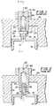
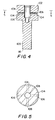
- FIG. 4 is a simplified cross sectional view of an illustrative embodiment of the self-clipping slave piston of the present invention.
- FIG. 5 is a simplified cross sectional view taken along the line 5-5 in FIG. 4.
- FIG. 6 is a simplified cross-sectional view of an illustrative embodiment of the self-clipping slave piston of the present invention in the closed position.
- FIG. 7 is a view similar to FIG. 6 showing the self-clipping slave piston of FIG. 6 as it is opening.
- In the conventional system shown in FIGS. 1 and 2,
slave piston 10 reciprocates inslave piston cylinder 32 alonglongitudinal axis 60 inhousing 30. The initial position ofslave piston 10 is determined by the adjustment ofscrew 70, which is held in place againsthousing 30 bynut 40. The overall operation of the general type of compression relief engine retarder system that uses the present invention is further shown in FIG. 3. In operation a high pressure pulse, generally in the range of 2000-4000 psi, is generated by the rotation ofengine injection cam 340, which urgesarm 335 to moverocker arm 325 viamember 330, urgingmaster piston 320 against the hydraulic fluid inhigh pressure passage 302 of a hydraulic circuit. This pulse is transmitted through the hydraulic circuit toslave piston cylinder 32 via aperture 34. The force of the pressurized hydraulic fluid againsttop end face 14 ofslave piston 10 causesslave piston 10 to move alonglongitudinal axis 60 in a downward direction so thatslave piston 10urges member 350 downward, holdingopen exhaust valve 312. Plunger 20, which reciprocates in the hollow portion ofscrew 70, has aslot 28 through whichpin 22 is inserted.Pin 22 is press-fit intoscrew 70. The excursion ofplunger 20 is determined by the location ofpin 22 between thetop 24 and thebottom 26 ofslot 28. During the downward travel ofslave piston 10,plunger 20 is held againstaperture 12 ofslave piston 10 byspring 50 so as to block the escape of hydraulic fluid until thetop 24 ofslot 28 comes into contact withpin 22 as shown in FIGS. 1 and 2.Spring 50 has sufficient strength to hold the flat lower end face ofplunger 20 against the flatupper surface 14 ofslave piston 10, forming a "face fit" between the two end faces. - When top 24 of
slot 28contacts pin 22,slave piston 10 separates fromplunger 20. This allows hydraulic fluid to escape fromslave piston cylinder 32 throughaperture 12 inslave piston 10 and vialow pressure passage 304 intorecovery area 360, thereby automatically limiting the downward travel ofslave piston 10 and the amount by which the associated exhaust valve is opened. When the master piston no longer applies the high pressure pulse,slave piston 10 is driven back up to its initial position byspring 352 viamember 350. - Although the conventional slave piston system with the mechanism for clipping the displacement of the slave piston described above is superior to those systems without such capabilities, there is room for improvement of the design. For instance, the operation of press-fitting
pin 22 intoscrew 70 is difficult to achieve reliably, requiring a "reverse push test" to check whether the pin is secure. Another disadvantage of the conventional design is its reliance on the face fit betweenend face 14 ofslave piston 10 and the lower end face ofplunger 20, an approach which requires that the two end faces be extremely flat. - In the clipping mechanism of this invention as shown in FIGS. 4-7,
slave piston 100 reciprocates alonglongitudinal axis 180 withinslave piston cylinder 114, contained inhousing 210. Withinslave piston 100 arebores aperture 112. Valvemember 120, which is held in place against thelower end face 134 ofscrew 130 byspring 140, reciprocates inbore 108 alonglongitudinal axis 180. Valvemember 120 makes a "lap fit" alongwall 110 ofbore 108 withslave piston 100. The slave piston system also incorporates retaining ring 170, which is used to containvalve member 120 andspring 140 withinbore 108 during assembly. - The initial position of
lower end face 116 ofslave piston 100 with respect to the exhaust valve (not shown) that is acted upon byslave piston 100 is determined by the adjustment of lash-adjustingscrew 130 and fixed by tighteningnut 200. Note that hydraulic fluid in theupper region 115 ofslave piston cylinder 114 flows intobore 108 both abovevalve member 120 and below it viaslot 123 inscrew 130 and viaaperture 124 invalve member 120. - The self-clipping slave piston operates as follows: at the beginning of a cycle, when
source 220 supplies relatively low pressure hydraulic fluid, the position of the elements is as shown in FIG. 6.Slave piston 100 is urged upwards againstlower portion 132 ofscrew 130 byspring 192, which acts againstsupport member 190. A high pressure hydraulic fluid pulse is produced byvariable pressure source 220. Typically this pulse is produced as was shown in FIG. 3. The pulse is transmitted viapassage 150 intoupper region 115 ofslave piston cylinder 114 where the resulting pressure againsttop end face 102 ofslave piston 100 forces it in a downward direction. - Referring now to FIG. 7, as
slave piston 100 moves down,valve member 120 remains in contact with thelower surface 134 ofscrew 130. Accordingly, thelower edge 126 ofvalve member 120 eventually uncoversaperture 112, which connectsbore 108 withbores 106.Circumferential groove 104 inslave piston 100 andaperture 162 inhousing 210 are prearranged, so that they are aligned at the same time or prior to the uncovering ofaperture 112 byvalve member 120. Thus, as shown in FIG. 7, whenslave piston 100 has reached the position inslave piston cylinder 114 that uncoversaperture 112, high pressure hydraulic fluid can escape frombore 108 via the one ofbores 106 that is aligned with passage way 160,circumferential groove 104, and passageway 160. Passageway 160 is connected to a low pressure hydraulic fluid recovery area (similar torecovery area 360, shown in FIG. 3). When the pressure ontop surface 102 ofslave piston 100 is reduced,spring 192 quickly forcesslave piston 100 in an upward direction alonglongitudinal axis 180 toward its initial position in the cycle. - In contrast to the prior art slave piston arrangement described previously, the present invention overcomes the need for
pin 22 while additionally providing a better lap-fit seal. In addition, the prior art hollow lash-adjustingscrew 70 has been replaced in the current invention bysolid screw 130. - The terms and expressions which have been employed are used as terms of description and not of limitation, and there is no intention in the use of such terms and expressions of excluding any equivalents of the features shown and described or portions thereof, but it is recognized that various modifications are possible within the scope of the invention claimed.
Claims (11)
- Apparatus for limiting the travel of a slave piston in a slave piston cylinder in a compression relief engine retarder, said cylinder being connected in a hydraulic circuit so that when hydraulic fluid is forced into said cylinder at one end of said slave piston, said slave piston moves along a longitudinal axis of said cylinder, said apparatus comprising:
a first bore disposed in said slave piston, said first bore having side walls which are substantially parallel to said longitudinal axis, said first bore communicating with said hydraulic fluid in said cylinder at said one end of said slave piston;
a second bore disposed in said slave piston, said second bore communicating with said first bore via a first aperture in the walls of said first bore;
a valve member disposed in said first bore for reciprocation relative to said slave piston substantially parallel to said longitudinal axis between (a) a closed position in which said valve member covers said first aperture and substantially prevents hydraulic fluid from flowing from said first bore into said second bore and (b) an open position in which said valve member at least partly opens said first aperture and allows hydraulic fluid to escape from said first bore via said second bore; and
means for maintaining said valve member substantially in a predetermined position relative to said cylinder along said longitudinal axis so that said valve member is initially in said closed position and, after a predetermined amount of travel of said slave piston in response to the forcing of hydraulic fluid into said cylinder, is in said open position. - The apparatus of claim 1 wherein said second bore of said slave piston allows the hydraulic fluid to escape from said slave piston via a second aperture in an exterior wall of said slave piston.
- The apparatus of claim 1 wherein said first bore further comprises a recess for holding a retaining ring disposed adjacent to said side walls of said first bore.
- The apparatus of claim 1 wherein said cylinder is disposed in a housing, and wherein said apparatus further comprises a first passage in said housing, said first passage communicating with said cylinder at said one end of said slave piston, said first passage additionally communicating with a variable pressure source of hydraulic fluid.
- The apparatus of claim 1 wherein said cylinder is disposed in a housing, and wherein the means for maintaining said valve member in said predetermined position along said longitudinal axis comprises an adjustable screw disposed adjacent to said slave piston.
- The apparatus of claim 5 wherein said means for maintaining said valve member in said predetermined position further comprises a first spring disposed adjacent to said valve member for holding said valve member substantially against said adjustable screw.
- The apparatus of claim 5 wherein said adjustable screw is substantially solid.
- The apparatus of claim 5 wherein said slave piston is in a first position relative to said cylinder along said longitudinal axis when said valve member is in said closed position and said slave piston is in a second position relative to said cylinder along said longitudinal axis when said valve member is in said open position, said adjustable screw being disposed adjacent to said slave piston such that said first position is determined by the relative location of said adjustable screw along said longitudinal axis.
- The apparatus of claim 8 wherein said slave piston is urged along said longitudinal axis toward said first position by a second spring, said second spring being disposed adjacent to said slave piston and attached to said housing.
- The apparatus of claim 8 wherein said screw is disposed in said housing and a nut is disposed on said screw adjacent to said housing, said nut holding said adjustable screw such that said first position is substantially fixed.
- The apparatus of claim 8 further comprising a second passage in said housing, said second passage communicating with said cylinder via a third aperture, wherein the hydraulic fluid that escapes from said first bore via said second bore further flows via said second aperture and via said third aperture into said second passage when said valve member is in said open position.
Applications Claiming Priority (2)
| Application Number | Priority Date | Filing Date | Title |
|---|---|---|---|
| US07/816,665 US5161501A (en) | 1992-01-03 | 1992-01-03 | Self-clippping slave piston |
| US816665 | 2001-03-23 |
Publications (2)
| Publication Number | Publication Date |
|---|---|
| EP0549997A1 true EP0549997A1 (en) | 1993-07-07 |
| EP0549997B1 EP0549997B1 (en) | 1996-04-24 |
Family
ID=25221307
Family Applications (1)
| Application Number | Title | Priority Date | Filing Date |
|---|---|---|---|
| EP92121781A Expired - Lifetime EP0549997B1 (en) | 1992-01-03 | 1992-12-22 | Self-clipping slave piston |
Country Status (6)
| Country | Link |
|---|---|
| US (1) | US5161501A (en) |
| EP (1) | EP0549997B1 (en) |
| JP (1) | JPH0742520A (en) |
| CA (1) | CA2085934A1 (en) |
| DE (1) | DE69210194T2 (en) |
| MX (1) | MX9207668A (en) |
Cited By (2)
| Publication number | Priority date | Publication date | Assignee | Title |
|---|---|---|---|---|
| WO1996010125A1 (en) * | 1994-09-28 | 1996-04-04 | Diesel Engine Retarders, Inc. | Hydraulic circuits for compression release engine brakes |
| EP1009921A1 (en) * | 1997-07-14 | 2000-06-21 | Diesel Engine Retarders, Inc. | Applied lost motion for optimization of fixed timed engine brake systems |
Families Citing this family (21)
| Publication number | Priority date | Publication date | Assignee | Title |
|---|---|---|---|---|
| US5347968A (en) * | 1993-05-24 | 1994-09-20 | Caterpillar Inc. | Integral air compression system |
| US5357926A (en) * | 1993-08-26 | 1994-10-25 | Jacobs Brake Technology Corporation | Compression release engine brake with selectively reduced engine exhaust noise |
| US5540201A (en) | 1994-07-29 | 1996-07-30 | Caterpillar Inc. | Engine compression braking apparatus and method |
| US5595158A (en) * | 1994-07-29 | 1997-01-21 | Caterpillar Inc. | Dynamic positioning device for an engine brake control |
| US5647318A (en) | 1994-07-29 | 1997-07-15 | Caterpillar Inc. | Engine compression braking apparatus and method |
| US5619963A (en) * | 1994-07-29 | 1997-04-15 | Caterpillar Inc. | Dual force actuator for use in engine retarding systems |
| US5526784A (en) | 1994-08-04 | 1996-06-18 | Caterpillar Inc. | Simultaneous exhaust valve opening braking system |
| US5460131A (en) * | 1994-09-28 | 1995-10-24 | Diesel Engine Retarders, Inc. | Compact combined lash adjuster and reset mechanism for compression release engine brakes |
| US5511460A (en) * | 1995-01-25 | 1996-04-30 | Diesel Engine Retarders, Inc. | Stroke limiter for hydraulic actuator pistons in compression release engine brakes |
| US5809964A (en) | 1997-02-03 | 1998-09-22 | Diesel Engine Retarders, Inc. | Method and apparatus to accomplish exhaust air recirculation during engine braking and/or exhaust gas recirculation during positive power operation of an internal combustion engine |
| US6240898B1 (en) | 1997-10-15 | 2001-06-05 | Diesel Engine Retarders, Inc. | Slave piston assembly with valve motion modifier |
| US8820276B2 (en) | 1997-12-11 | 2014-09-02 | Jacobs Vehicle Systems, Inc. | Variable lost motion valve actuator and method |
| JP2002502004A (en) * | 1998-02-02 | 2002-01-22 | ディーゼル エンジン リターダーズ,インコーポレイテッド | Self-braking slave piston arrangement with backlash adjustment for compression-release engine brakes |
| US6085721A (en) * | 1998-04-03 | 2000-07-11 | Diesel Engine Retarders, Inc. | Bar engine brake |
| WO2000011336A1 (en) | 1998-08-19 | 2000-03-02 | Diesel Engine Retarders, Inc. | Hydraulically-actuated fail-safe stroke-limiting piston |
| US6405707B1 (en) * | 2000-12-18 | 2002-06-18 | Caterpillar Inc. | Integral engine and engine compression braking HEUI injector |
| US6957634B2 (en) * | 2002-10-04 | 2005-10-25 | Caterpillar Inc. | Engine valve actuator |
| US6708656B1 (en) | 2002-12-19 | 2004-03-23 | Caterpillar Inc | Engine valve actuator |
| US6997148B1 (en) | 2004-10-15 | 2006-02-14 | Caterpillar Inc. | Engine valve actuator |
| KR101290347B1 (en) * | 2011-08-30 | 2013-07-26 | 현대제철 주식회사 | Estimation method of reduction degradation within furnace based on reduction time |
| US9200541B2 (en) * | 2012-07-20 | 2015-12-01 | Jacobs Vehicle Systems, Inc. | Systems and methods for hydraulic lash adjustment in an internal combustion engine |
Citations (2)
| Publication number | Priority date | Publication date | Assignee | Title |
|---|---|---|---|---|
| US3547087A (en) * | 1968-08-09 | 1970-12-15 | White Motor Corp | Engine valve control for braking operation |
| US5000145A (en) * | 1989-12-05 | 1991-03-19 | Quenneville Raymond N | Compression release retarding system |
Family Cites Families (10)
| Publication number | Priority date | Publication date | Assignee | Title |
|---|---|---|---|---|
| US2847261A (en) * | 1956-07-19 | 1958-08-12 | Richard T Cornelius | Piston construction |
| US3220392A (en) * | 1962-06-04 | 1965-11-30 | Clessie L Cummins | Vehicle engine braking and fuel control system |
| US3405699A (en) * | 1966-06-17 | 1968-10-15 | Jacobs Mfg Co | Engine braking system with trip valve controlled piston |
| US4381179A (en) * | 1980-10-31 | 1983-04-26 | Lear Siegler, Inc. | Pumps with floating wrist pins |
| US4399787A (en) * | 1981-12-24 | 1983-08-23 | The Jacobs Manufacturing Company | Engine retarder hydraulic reset mechanism |
| US4423712A (en) * | 1982-04-28 | 1984-01-03 | The Jacobs Mfg. Company | Engine retarder slave piston return mechanism |
| US4592319A (en) * | 1985-08-09 | 1986-06-03 | The Jacobs Manufacturing Company | Engine retarding method and apparatus |
| US4742806A (en) * | 1986-09-10 | 1988-05-10 | Tart Jr Earl D | Auxiliary engine braking system |
| US4741307A (en) * | 1987-02-17 | 1988-05-03 | Pacific Diesel Brave Co. | Apparatus and method for compression release retarding of an engine |
| US5036810A (en) * | 1990-08-07 | 1991-08-06 | Jenara Enterprises Ltd. | Engine brake and method |
-
1992
- 1992-01-03 US US07/816,665 patent/US5161501A/en not_active Expired - Fee Related
- 1992-12-21 CA CA002085934A patent/CA2085934A1/en not_active Abandoned
- 1992-12-22 EP EP92121781A patent/EP0549997B1/en not_active Expired - Lifetime
- 1992-12-22 DE DE69210194T patent/DE69210194T2/en not_active Expired - Fee Related
- 1992-12-30 MX MX9207668A patent/MX9207668A/en unknown
-
1993
- 1993-01-04 JP JP5014395A patent/JPH0742520A/en active Pending
Patent Citations (2)
| Publication number | Priority date | Publication date | Assignee | Title |
|---|---|---|---|---|
| US3547087A (en) * | 1968-08-09 | 1970-12-15 | White Motor Corp | Engine valve control for braking operation |
| US5000145A (en) * | 1989-12-05 | 1991-03-19 | Quenneville Raymond N | Compression release retarding system |
Cited By (3)
| Publication number | Priority date | Publication date | Assignee | Title |
|---|---|---|---|---|
| WO1996010125A1 (en) * | 1994-09-28 | 1996-04-04 | Diesel Engine Retarders, Inc. | Hydraulic circuits for compression release engine brakes |
| EP1009921A1 (en) * | 1997-07-14 | 2000-06-21 | Diesel Engine Retarders, Inc. | Applied lost motion for optimization of fixed timed engine brake systems |
| EP1009921A4 (en) * | 1997-07-14 | 2000-07-19 | Diesel Engine Retarders Inc | Applied lost motion for optimization of fixed timed engine brake systems |
Also Published As
| Publication number | Publication date |
|---|---|
| DE69210194D1 (en) | 1996-05-30 |
| JPH0742520A (en) | 1995-02-10 |
| US5161501A (en) | 1992-11-10 |
| MX9207668A (en) | 1994-05-31 |
| EP0549997B1 (en) | 1996-04-24 |
| CA2085934A1 (en) | 1993-07-04 |
| DE69210194T2 (en) | 1996-09-05 |
Similar Documents
| Publication | Publication Date | Title |
|---|---|---|
| US5161501A (en) | Self-clippping slave piston | |
| EP0549996B1 (en) | Compression relief engine retarder clip valve | |
| EP0083058B1 (en) | Retarding system of a gas compression relief type | |
| US5000145A (en) | Compression release retarding system | |
| US4572114A (en) | Process and apparatus for compression release engine retarding producing two compression release events per cylinder per engine cycle | |
| US4706625A (en) | Engine retarder with reset auto-lash mechanism | |
| US5460131A (en) | Compact combined lash adjuster and reset mechanism for compression release engine brakes | |
| EP0249833B1 (en) | An engine retarding system and method of a gas compression release type | |
| US5193494A (en) | Valve operating system for internal combustion engine | |
| EP0828061A1 (en) | Exhaust pulse boosted engine compression braking method | |
| EP1734252A3 (en) | High pressure fuel pump for internal combustion engine | |
| US5711279A (en) | Fuel system | |
| US5511460A (en) | Stroke limiter for hydraulic actuator pistons in compression release engine brakes | |
| US5183018A (en) | Master cylinder with two-piece master piston | |
| EP1218635B1 (en) | Timing advance piston for a fuel injection pump | |
| US4898206A (en) | Compression release retarder with valve motion modifier | |
| US4838516A (en) | Compression release retarder with valve motion modifier | |
| US6095115A (en) | Self-clipping slave piston device with lash adjustment for a compression release engine retarder | |
| US4949751A (en) | Compression release retarder with valve motion modifier | |
| WO2002086305A3 (en) | Fuel injection device for an internal combustion engine | |
| JPS584164B2 (en) | Piston reciprocating internal combustion engine | |
| JPH0634102U (en) | Valve drive for internal combustion engine | |
| NZ217093A (en) | Compression release 1.c.engine retarding process using electronic control of hydraulic circuits for valve actuation | |
| JPH04287812A (en) | Hydraulically driving device for engine valve for internal combustion engine |
Legal Events
| Date | Code | Title | Description |
|---|---|---|---|
| PUAI | Public reference made under article 153(3) epc to a published international application that has entered the european phase |
Free format text: ORIGINAL CODE: 0009012 |
|
| AK | Designated contracting states |
Kind code of ref document: A1 Designated state(s): DE GB SE |
|
| 17P | Request for examination filed |
Effective date: 19931210 |
|
| 17Q | First examination report despatched |
Effective date: 19941121 |
|
| GRAH | Despatch of communication of intention to grant a patent |
Free format text: ORIGINAL CODE: EPIDOS IGRA |
|
| GRAA | (expected) grant |
Free format text: ORIGINAL CODE: 0009210 |
|
| AK | Designated contracting states |
Kind code of ref document: B1 Designated state(s): DE GB SE |
|
| REF | Corresponds to: |
Ref document number: 69210194 Country of ref document: DE Date of ref document: 19960530 |
|
| PLBE | No opposition filed within time limit |
Free format text: ORIGINAL CODE: 0009261 |
|
| STAA | Information on the status of an ep patent application or granted ep patent |
Free format text: STATUS: NO OPPOSITION FILED WITHIN TIME LIMIT |
|
| 26N | No opposition filed | ||
| REG | Reference to a national code |
Ref country code: GB Ref legal event code: IF02 |
|
| PGFP | Annual fee paid to national office [announced via postgrant information from national office to epo] |
Ref country code: SE Payment date: 20020118 Year of fee payment: 10 Ref country code: DE Payment date: 20020118 Year of fee payment: 10 |
|
| PGFP | Annual fee paid to national office [announced via postgrant information from national office to epo] |
Ref country code: GB Payment date: 20020121 Year of fee payment: 10 |
|
| PG25 | Lapsed in a contracting state [announced via postgrant information from national office to epo] |
Ref country code: GB Free format text: LAPSE BECAUSE OF NON-PAYMENT OF DUE FEES Effective date: 20021222 |
|
| PG25 | Lapsed in a contracting state [announced via postgrant information from national office to epo] |
Ref country code: SE Free format text: LAPSE BECAUSE OF NON-PAYMENT OF DUE FEES Effective date: 20021223 |
|
| PG25 | Lapsed in a contracting state [announced via postgrant information from national office to epo] |
Ref country code: DE Free format text: LAPSE BECAUSE OF NON-PAYMENT OF DUE FEES Effective date: 20030701 |
|
| EUG | Se: european patent has lapsed | ||
| GBPC | Gb: european patent ceased through non-payment of renewal fee |
Effective date: 20021222 |