EP0549670B1 - Polymer membrane - Google Patents
Polymer membrane Download PDFInfo
- Publication number
- EP0549670B1 EP0549670B1 EP91916836A EP91916836A EP0549670B1 EP 0549670 B1 EP0549670 B1 EP 0549670B1 EP 91916836 A EP91916836 A EP 91916836A EP 91916836 A EP91916836 A EP 91916836A EP 0549670 B1 EP0549670 B1 EP 0549670B1
- Authority
- EP
- European Patent Office
- Prior art keywords
- matrix
- membrane
- polymeric material
- crosslinking
- pores
- Prior art date
- Legal status (The legal status is an assumption and is not a legal conclusion. Google has not performed a legal analysis and makes no representation as to the accuracy of the status listed.)
- Expired - Lifetime
Links
- 229920005597 polymer membrane Polymers 0.000 title claims abstract description 18
- 239000000463 material Substances 0.000 claims abstract description 131
- 239000011159 matrix material Substances 0.000 claims abstract description 85
- 239000012528 membrane Substances 0.000 claims abstract description 59
- 238000004132 cross linking Methods 0.000 claims abstract description 49
- 239000011148 porous material Substances 0.000 claims abstract description 34
- 239000002131 composite material Substances 0.000 claims abstract description 17
- 150000001732 carboxylic acid derivatives Chemical class 0.000 claims abstract description 4
- 238000000034 method Methods 0.000 claims description 34
- -1 polyethylene Polymers 0.000 claims description 25
- 239000000203 mixture Substances 0.000 claims description 18
- 239000004698 Polyethylene Substances 0.000 claims description 17
- 239000000178 monomer Substances 0.000 claims description 17
- 229920000573 polyethylene Polymers 0.000 claims description 17
- 238000006243 chemical reaction Methods 0.000 claims description 13
- 230000005855 radiation Effects 0.000 claims description 11
- 125000000391 vinyl group Chemical group [H]C([*])=C([H])[H] 0.000 claims description 10
- 229920002554 vinyl polymer Polymers 0.000 claims description 10
- 150000003839 salts Chemical class 0.000 claims description 9
- 239000002253 acid Substances 0.000 claims description 8
- 239000002904 solvent Substances 0.000 claims description 8
- 229920000642 polymer Polymers 0.000 claims description 6
- 229920000098 polyolefin Polymers 0.000 claims description 6
- 150000002148 esters Chemical class 0.000 claims description 4
- 238000004519 manufacturing process Methods 0.000 claims description 4
- 230000008569 process Effects 0.000 claims description 4
- JPVYNHNXODAKFH-UHFFFAOYSA-N Cu2+ Chemical class [Cu+2] JPVYNHNXODAKFH-UHFFFAOYSA-N 0.000 claims description 2
- 230000015572 biosynthetic process Effects 0.000 claims description 2
- 239000003112 inhibitor Substances 0.000 claims description 2
- 239000011244 liquid electrolyte Substances 0.000 claims description 2
- CWYNVVGOOAEACU-UHFFFAOYSA-N Fe2+ Chemical group [Fe+2] CWYNVVGOOAEACU-UHFFFAOYSA-N 0.000 claims 1
- BAUYGSIQEAFULO-UHFFFAOYSA-L iron(2+) sulfate (anhydrous) Chemical compound [Fe+2].[O-]S([O-])(=O)=O BAUYGSIQEAFULO-UHFFFAOYSA-L 0.000 claims 1
- 230000004888 barrier function Effects 0.000 abstract description 20
- KWYUFKZDYYNOTN-UHFFFAOYSA-M Potassium hydroxide Chemical compound [OH-].[K+] KWYUFKZDYYNOTN-UHFFFAOYSA-M 0.000 description 24
- SMZOUWXMTYCWNB-UHFFFAOYSA-N 2-(2-methoxy-5-methylphenyl)ethanamine Chemical compound COC1=CC=C(C)C=C1CCN SMZOUWXMTYCWNB-UHFFFAOYSA-N 0.000 description 22
- NIXOWILDQLNWCW-UHFFFAOYSA-N 2-Propenoic acid Natural products OC(=O)C=C NIXOWILDQLNWCW-UHFFFAOYSA-N 0.000 description 22
- CSCPPACGZOOCGX-UHFFFAOYSA-N Acetone Chemical compound CC(C)=O CSCPPACGZOOCGX-UHFFFAOYSA-N 0.000 description 13
- 239000003431 cross linking reagent Substances 0.000 description 11
- 239000010410 layer Substances 0.000 description 10
- MYRTYDVEIRVNKP-UHFFFAOYSA-N 1,2-Divinylbenzene Chemical compound C=CC1=CC=CC=C1C=C MYRTYDVEIRVNKP-UHFFFAOYSA-N 0.000 description 8
- 230000008901 benefit Effects 0.000 description 8
- 230000000694 effects Effects 0.000 description 7
- 238000005342 ion exchange Methods 0.000 description 7
- 150000002500 ions Chemical class 0.000 description 7
- 238000012546 transfer Methods 0.000 description 7
- YXFVVABEGXRONW-UHFFFAOYSA-N Toluene Chemical compound CC1=CC=CC=C1 YXFVVABEGXRONW-UHFFFAOYSA-N 0.000 description 6
- RWCCWEUUXYIKHB-UHFFFAOYSA-N benzophenone Chemical compound C=1C=CC=CC=1C(=O)C1=CC=CC=C1 RWCCWEUUXYIKHB-UHFFFAOYSA-N 0.000 description 6
- 239000012965 benzophenone Substances 0.000 description 6
- 238000010924 continuous production Methods 0.000 description 6
- 239000007788 liquid Substances 0.000 description 6
- 229910052753 mercury Inorganic materials 0.000 description 6
- 238000000605 extraction Methods 0.000 description 5
- 239000003999 initiator Substances 0.000 description 5
- QSHDDOUJBYECFT-UHFFFAOYSA-N mercury Chemical compound [Hg] QSHDDOUJBYECFT-UHFFFAOYSA-N 0.000 description 5
- 229910052709 silver Inorganic materials 0.000 description 5
- 239000004332 silver Substances 0.000 description 5
- NDVLTYZPCACLMA-UHFFFAOYSA-N silver oxide Chemical compound [O-2].[Ag+].[Ag+] NDVLTYZPCACLMA-UHFFFAOYSA-N 0.000 description 5
- KWOLFJPFCHCOCG-UHFFFAOYSA-N Acetophenone Chemical compound CC(=O)C1=CC=CC=C1 KWOLFJPFCHCOCG-UHFFFAOYSA-N 0.000 description 4
- 229920003171 Poly (ethylene oxide) Polymers 0.000 description 4
- 210000004027 cell Anatomy 0.000 description 4
- 239000008367 deionised water Substances 0.000 description 4
- 239000003792 electrolyte Substances 0.000 description 4
- 238000011065 in-situ storage Methods 0.000 description 4
- 230000007246 mechanism Effects 0.000 description 4
- VEXZGXHMUGYJMC-UHFFFAOYSA-N Hydrochloric acid Chemical compound Cl VEXZGXHMUGYJMC-UHFFFAOYSA-N 0.000 description 3
- OKKJLVBELUTLKV-UHFFFAOYSA-N Methanol Chemical compound OC OKKJLVBELUTLKV-UHFFFAOYSA-N 0.000 description 3
- 239000004743 Polypropylene Substances 0.000 description 3
- 229920002125 Sokalan® Polymers 0.000 description 3
- 238000010923 batch production Methods 0.000 description 3
- 230000005012 migration Effects 0.000 description 3
- 238000013508 migration Methods 0.000 description 3
- 239000004584 polyacrylic acid Substances 0.000 description 3
- 229920001155 polypropylene Polymers 0.000 description 3
- 229940117958 vinyl acetate Drugs 0.000 description 3
- XLYOFNOQVPJJNP-UHFFFAOYSA-N water Substances O XLYOFNOQVPJJNP-UHFFFAOYSA-N 0.000 description 3
- KOMNUTZXSVSERR-UHFFFAOYSA-N 1,3,5-tris(prop-2-enyl)-1,3,5-triazinane-2,4,6-trione Chemical compound C=CCN1C(=O)N(CC=C)C(=O)N(CC=C)C1=O KOMNUTZXSVSERR-UHFFFAOYSA-N 0.000 description 2
- XWJBRBSPAODJER-UHFFFAOYSA-N 1,7-octadiene Chemical compound C=CCCCCC=C XWJBRBSPAODJER-UHFFFAOYSA-N 0.000 description 2
- BJELTSYBAHKXRW-UHFFFAOYSA-N 2,4,6-triallyloxy-1,3,5-triazine Chemical compound C=CCOC1=NC(OCC=C)=NC(OCC=C)=N1 BJELTSYBAHKXRW-UHFFFAOYSA-N 0.000 description 2
- ZWEHNKRNPOVVGH-UHFFFAOYSA-N 2-Butanone Chemical compound CCC(C)=O ZWEHNKRNPOVVGH-UHFFFAOYSA-N 0.000 description 2
- KGIGUEBEKRSTEW-UHFFFAOYSA-N 2-vinylpyridine Chemical class C=CC1=CC=CC=N1 KGIGUEBEKRSTEW-UHFFFAOYSA-N 0.000 description 2
- VGGSQFUCUMXWEO-UHFFFAOYSA-N Ethene Chemical compound C=C VGGSQFUCUMXWEO-UHFFFAOYSA-N 0.000 description 2
- 239000005977 Ethylene Substances 0.000 description 2
- BAPJBEWLBFYGME-UHFFFAOYSA-N Methyl acrylate Chemical compound COC(=O)C=C BAPJBEWLBFYGME-UHFFFAOYSA-N 0.000 description 2
- BQCADISMDOOEFD-UHFFFAOYSA-N Silver Chemical compound [Ag] BQCADISMDOOEFD-UHFFFAOYSA-N 0.000 description 2
- XTXRWKRVRITETP-UHFFFAOYSA-N Vinyl acetate Chemical compound CC(=O)OC=C XTXRWKRVRITETP-UHFFFAOYSA-N 0.000 description 2
- 239000006096 absorbing agent Substances 0.000 description 2
- 238000013459 approach Methods 0.000 description 2
- 230000000052 comparative effect Effects 0.000 description 2
- 125000004386 diacrylate group Chemical group 0.000 description 2
- 125000004435 hydrogen atom Chemical group [H]* 0.000 description 2
- 230000000704 physical effect Effects 0.000 description 2
- 229920002689 polyvinyl acetate Polymers 0.000 description 2
- 239000011118 polyvinyl acetate Substances 0.000 description 2
- 229920000915 polyvinyl chloride Polymers 0.000 description 2
- 239000004800 polyvinyl chloride Substances 0.000 description 2
- 229910001923 silver oxide Inorganic materials 0.000 description 2
- 239000007787 solid Substances 0.000 description 2
- 238000000108 ultra-filtration Methods 0.000 description 2
- PRBHEGAFLDMLAL-UHFFFAOYSA-N 1,5-Hexadiene Natural products CC=CCC=C PRBHEGAFLDMLAL-UHFFFAOYSA-N 0.000 description 1
- KWVGIHKZDCUPEU-UHFFFAOYSA-N 2,2-dimethoxy-2-phenylacetophenone Chemical compound C=1C=CC=CC=1C(OC)(OC)C(=O)C1=CC=CC=C1 KWVGIHKZDCUPEU-UHFFFAOYSA-N 0.000 description 1
- DSAYAFZWRDYBQY-UHFFFAOYSA-N 2,5-dimethylhexa-1,5-diene Chemical compound CC(=C)CCC(C)=C DSAYAFZWRDYBQY-UHFFFAOYSA-N 0.000 description 1
- XNWFRZJHXBZDAG-UHFFFAOYSA-N 2-METHOXYETHANOL Chemical compound COCCO XNWFRZJHXBZDAG-UHFFFAOYSA-N 0.000 description 1
- YQUDMNIUBTXLSX-UHFFFAOYSA-N 2-ethenyl-5-ethylpyridine Chemical compound CCC1=CC=C(C=C)N=C1 YQUDMNIUBTXLSX-UHFFFAOYSA-N 0.000 description 1
- VAPQAGMSICPBKJ-UHFFFAOYSA-N 2-nitroacridine Chemical compound C1=CC=CC2=CC3=CC([N+](=O)[O-])=CC=C3N=C21 VAPQAGMSICPBKJ-UHFFFAOYSA-N 0.000 description 1
- UGVRJVHOJNYEHR-UHFFFAOYSA-N 4-chlorobenzophenone Chemical compound C1=CC(Cl)=CC=C1C(=O)C1=CC=CC=C1 UGVRJVHOJNYEHR-UHFFFAOYSA-N 0.000 description 1
- VJOWMORERYNYON-UHFFFAOYSA-N 5-ethenyl-2-methylpyridine Chemical compound CC1=CC=C(C=C)C=N1 VJOWMORERYNYON-UHFFFAOYSA-N 0.000 description 1
- HRPVXLWXLXDGHG-UHFFFAOYSA-N Acrylamide Chemical compound NC(=O)C=C HRPVXLWXLXDGHG-UHFFFAOYSA-N 0.000 description 1
- JIGUQPWFLRLWPJ-UHFFFAOYSA-N Ethyl acrylate Chemical compound CCOC(=O)C=C JIGUQPWFLRLWPJ-UHFFFAOYSA-N 0.000 description 1
- GLZPCOQZEFWAFX-UHFFFAOYSA-N Geraniol Chemical compound CC(C)=CCCC(C)=CCO GLZPCOQZEFWAFX-UHFFFAOYSA-N 0.000 description 1
- CERQOIWHTDAKMF-UHFFFAOYSA-N Methacrylic acid Chemical compound CC(=C)C(O)=O CERQOIWHTDAKMF-UHFFFAOYSA-N 0.000 description 1
- GRYLNZFGIOXLOG-UHFFFAOYSA-N Nitric acid Chemical compound O[N+]([O-])=O GRYLNZFGIOXLOG-UHFFFAOYSA-N 0.000 description 1
- 239000004952 Polyamide Substances 0.000 description 1
- 239000002202 Polyethylene glycol Substances 0.000 description 1
- OFOBLEOULBTSOW-UHFFFAOYSA-N Propanedioic acid Natural products OC(=O)CC(O)=O OFOBLEOULBTSOW-UHFFFAOYSA-N 0.000 description 1
- 238000010521 absorption reaction Methods 0.000 description 1
- 150000007513 acids Chemical class 0.000 description 1
- 150000001253 acrylic acids Chemical class 0.000 description 1
- 150000001491 aromatic compounds Chemical class 0.000 description 1
- ZWPWLKXZYNXATK-UHFFFAOYSA-N bis(4-methylphenyl)methanone Chemical compound C1=CC(C)=CC=C1C(=O)C1=CC=C(C)C=C1 ZWPWLKXZYNXATK-UHFFFAOYSA-N 0.000 description 1
- 239000013590 bulk material Substances 0.000 description 1
- 125000002915 carbonyl group Chemical group [*:2]C([*:1])=O 0.000 description 1
- 238000012505 colouration Methods 0.000 description 1
- 238000010276 construction Methods 0.000 description 1
- 229920001577 copolymer Polymers 0.000 description 1
- 229910001431 copper ion Inorganic materials 0.000 description 1
- ARUVKPQLZAKDPS-UHFFFAOYSA-L copper(II) sulfate Chemical compound [Cu+2].[O-][S+2]([O-])([O-])[O-] ARUVKPQLZAKDPS-UHFFFAOYSA-L 0.000 description 1
- 210000001787 dendrite Anatomy 0.000 description 1
- 230000001419 dependent effect Effects 0.000 description 1
- 238000013461 design Methods 0.000 description 1
- 238000009791 electrochemical migration reaction Methods 0.000 description 1
- 239000007772 electrode material Substances 0.000 description 1
- 238000001493 electron microscopy Methods 0.000 description 1
- 239000000284 extract Substances 0.000 description 1
- 238000011049 filling Methods 0.000 description 1
- 238000001914 filtration Methods 0.000 description 1
- 238000009472 formulation Methods 0.000 description 1
- 239000011521 glass Substances 0.000 description 1
- SZYLTIUVWARXOO-UHFFFAOYSA-N hexa-1,5-dien-3-ol Chemical compound C=CC(O)CC=C SZYLTIUVWARXOO-UHFFFAOYSA-N 0.000 description 1
- PYGSKMBEVAICCR-UHFFFAOYSA-N hexa-1,5-diene Chemical compound C=CCCC=C PYGSKMBEVAICCR-UHFFFAOYSA-N 0.000 description 1
- 230000007062 hydrolysis Effects 0.000 description 1
- 238000006460 hydrolysis reaction Methods 0.000 description 1
- 238000007654 immersion Methods 0.000 description 1
- XGZVUEUWXADBQD-UHFFFAOYSA-L lithium carbonate Chemical compound [Li+].[Li+].[O-]C([O-])=O XGZVUEUWXADBQD-UHFFFAOYSA-L 0.000 description 1
- 229910052808 lithium carbonate Inorganic materials 0.000 description 1
- VZCYOOQTPOCHFL-UPHRSURJSA-N maleic acid Chemical compound OC(=O)\C=C/C(O)=O VZCYOOQTPOCHFL-UPHRSURJSA-N 0.000 description 1
- 239000011976 maleic acid Substances 0.000 description 1
- FPYJFEHAWHCUMM-UHFFFAOYSA-N maleic anhydride Chemical compound O=C1OC(=O)C=C1 FPYJFEHAWHCUMM-UHFFFAOYSA-N 0.000 description 1
- 238000002156 mixing Methods 0.000 description 1
- YPHQUSNPXDGUHL-UHFFFAOYSA-N n-methylprop-2-enamide Chemical compound CNC(=O)C=C YPHQUSNPXDGUHL-UHFFFAOYSA-N 0.000 description 1
- 229910017604 nitric acid Inorganic materials 0.000 description 1
- 239000002736 nonionic surfactant Substances 0.000 description 1
- 239000002245 particle Substances 0.000 description 1
- 239000008188 pellet Substances 0.000 description 1
- PNJWIWWMYCMZRO-UHFFFAOYSA-N pent‐4‐en‐2‐one Natural products CC(=O)CC=C PNJWIWWMYCMZRO-UHFFFAOYSA-N 0.000 description 1
- 238000005191 phase separation Methods 0.000 description 1
- 239000004014 plasticizer Substances 0.000 description 1
- 229920002492 poly(sulfone) Polymers 0.000 description 1
- 229920002647 polyamide Polymers 0.000 description 1
- 229920000728 polyester Polymers 0.000 description 1
- 229920001223 polyethylene glycol Polymers 0.000 description 1
- 238000006116 polymerization reaction Methods 0.000 description 1
- 229920001343 polytetrafluoroethylene Polymers 0.000 description 1
- 239000004810 polytetrafluoroethylene Substances 0.000 description 1
- XAEFZNCEHLXOMS-UHFFFAOYSA-M potassium benzoate Chemical group [K+].[O-]C(=O)C1=CC=CC=C1 XAEFZNCEHLXOMS-UHFFFAOYSA-M 0.000 description 1
- 230000009257 reactivity Effects 0.000 description 1
- 238000010992 reflux Methods 0.000 description 1
- 238000000926 separation method Methods 0.000 description 1
- 239000002344 surface layer Substances 0.000 description 1
- 239000004094 surface-active agent Substances 0.000 description 1
- VZCYOOQTPOCHFL-UHFFFAOYSA-N trans-butenedioic acid Natural products OC(=O)C=CC(O)=O VZCYOOQTPOCHFL-UHFFFAOYSA-N 0.000 description 1
- 238000009736 wetting Methods 0.000 description 1
- 238000010626 work up procedure Methods 0.000 description 1
Images

Classifications
-
- B—PERFORMING OPERATIONS; TRANSPORTING
- B01—PHYSICAL OR CHEMICAL PROCESSES OR APPARATUS IN GENERAL
- B01D—SEPARATION
- B01D67/00—Processes specially adapted for manufacturing semi-permeable membranes for separation processes or apparatus
- B01D67/0081—After-treatment of organic or inorganic membranes
- B01D67/0088—Physical treatment with compounds, e.g. swelling, coating or impregnation
-
- B—PERFORMING OPERATIONS; TRANSPORTING
- B01—PHYSICAL OR CHEMICAL PROCESSES OR APPARATUS IN GENERAL
- B01D—SEPARATION
- B01D67/00—Processes specially adapted for manufacturing semi-permeable membranes for separation processes or apparatus
- B01D67/0081—After-treatment of organic or inorganic membranes
- B01D67/0093—Chemical modification
- B01D67/00931—Chemical modification by introduction of specific groups after membrane formation, e.g. by grafting
-
- B—PERFORMING OPERATIONS; TRANSPORTING
- B01—PHYSICAL OR CHEMICAL PROCESSES OR APPARATUS IN GENERAL
- B01D—SEPARATION
- B01D69/00—Semi-permeable membranes for separation processes or apparatus characterised by their form, structure or properties; Manufacturing processes specially adapted therefor
- B01D69/14—Dynamic membranes
- B01D69/141—Heterogeneous membranes, e.g. containing dispersed material; Mixed matrix membranes
-
- C—CHEMISTRY; METALLURGY
- C08—ORGANIC MACROMOLECULAR COMPOUNDS; THEIR PREPARATION OR CHEMICAL WORKING-UP; COMPOSITIONS BASED THEREON
- C08J—WORKING-UP; GENERAL PROCESSES OF COMPOUNDING; AFTER-TREATMENT NOT COVERED BY SUBCLASSES C08B, C08C, C08F, C08G or C08H
- C08J9/00—Working-up of macromolecular substances to porous or cellular articles or materials; After-treatment thereof
- C08J9/36—After-treatment
- C08J9/40—Impregnation
- C08J9/42—Impregnation with macromolecular compounds
-
- H—ELECTRICITY
- H01—ELECTRIC ELEMENTS
- H01M—PROCESSES OR MEANS, e.g. BATTERIES, FOR THE DIRECT CONVERSION OF CHEMICAL ENERGY INTO ELECTRICAL ENERGY
- H01M50/00—Constructional details or processes of manufacture of the non-active parts of electrochemical cells other than fuel cells, e.g. hybrid cells
- H01M50/40—Separators; Membranes; Diaphragms; Spacing elements inside cells
- H01M50/409—Separators, membranes or diaphragms characterised by the material
- H01M50/411—Organic material
- H01M50/414—Synthetic resins, e.g. thermoplastics or thermosetting resins
- H01M50/417—Polyolefins
-
- H—ELECTRICITY
- H01—ELECTRIC ELEMENTS
- H01M—PROCESSES OR MEANS, e.g. BATTERIES, FOR THE DIRECT CONVERSION OF CHEMICAL ENERGY INTO ELECTRICAL ENERGY
- H01M50/00—Constructional details or processes of manufacture of the non-active parts of electrochemical cells other than fuel cells, e.g. hybrid cells
- H01M50/40—Separators; Membranes; Diaphragms; Spacing elements inside cells
- H01M50/489—Separators, membranes, diaphragms or spacing elements inside the cells, characterised by their physical properties, e.g. swelling degree, hydrophilicity or shut down properties
- H01M50/491—Porosity
-
- H—ELECTRICITY
- H01—ELECTRIC ELEMENTS
- H01M—PROCESSES OR MEANS, e.g. BATTERIES, FOR THE DIRECT CONVERSION OF CHEMICAL ENERGY INTO ELECTRICAL ENERGY
- H01M50/00—Constructional details or processes of manufacture of the non-active parts of electrochemical cells other than fuel cells, e.g. hybrid cells
- H01M50/40—Separators; Membranes; Diaphragms; Spacing elements inside cells
- H01M50/489—Separators, membranes, diaphragms or spacing elements inside the cells, characterised by their physical properties, e.g. swelling degree, hydrophilicity or shut down properties
- H01M50/494—Tensile strength
-
- B—PERFORMING OPERATIONS; TRANSPORTING
- B01—PHYSICAL OR CHEMICAL PROCESSES OR APPARATUS IN GENERAL
- B01D—SEPARATION
- B01D2323/00—Details relating to membrane preparation
- B01D2323/30—Cross-linking
-
- B—PERFORMING OPERATIONS; TRANSPORTING
- B01—PHYSICAL OR CHEMICAL PROCESSES OR APPARATUS IN GENERAL
- B01D—SEPARATION
- B01D2323/00—Details relating to membrane preparation
- B01D2323/34—Use of radiation
- B01D2323/345—UV-treatment
-
- B—PERFORMING OPERATIONS; TRANSPORTING
- B01—PHYSICAL OR CHEMICAL PROCESSES OR APPARATUS IN GENERAL
- B01D—SEPARATION
- B01D2323/00—Details relating to membrane preparation
- B01D2323/38—Graft polymerization
-
- C—CHEMISTRY; METALLURGY
- C08—ORGANIC MACROMOLECULAR COMPOUNDS; THEIR PREPARATION OR CHEMICAL WORKING-UP; COMPOSITIONS BASED THEREON
- C08J—WORKING-UP; GENERAL PROCESSES OF COMPOUNDING; AFTER-TREATMENT NOT COVERED BY SUBCLASSES C08B, C08C, C08F, C08G or C08H
- C08J2433/00—Characterised by the use of homopolymers or copolymers of compounds having one or more unsaturated aliphatic radicals, each having only one carbon-to-carbon double bond, and only one being terminated by only one carboxyl radical, or of salts, anhydrides, esters, amides, imides, or nitriles thereof; Derivatives of such polymers
-
- Y—GENERAL TAGGING OF NEW TECHNOLOGICAL DEVELOPMENTS; GENERAL TAGGING OF CROSS-SECTIONAL TECHNOLOGIES SPANNING OVER SEVERAL SECTIONS OF THE IPC; TECHNICAL SUBJECTS COVERED BY FORMER USPC CROSS-REFERENCE ART COLLECTIONS [XRACs] AND DIGESTS
- Y02—TECHNOLOGIES OR APPLICATIONS FOR MITIGATION OR ADAPTATION AGAINST CLIMATE CHANGE
- Y02E—REDUCTION OF GREENHOUSE GAS [GHG] EMISSIONS, RELATED TO ENERGY GENERATION, TRANSMISSION OR DISTRIBUTION
- Y02E60/00—Enabling technologies; Technologies with a potential or indirect contribution to GHG emissions mitigation
- Y02E60/10—Energy storage using batteries
Definitions
- the present invention relates to polymer membranes.
- the invention relates in particular to a composite polymer membrane, a method of making a composite polymer membrane, and a method of crosslinking the material of a microporous polymer matrix.
- a composite polymer membrane which comprises a microporous matrix formed from a first polymeric material and a second polymeric material within the pores of the matrix, can be used as a selective barrier.
- a membrane may be used to separate components of a liquid.
- an ion exchange material as the second polymeric material
- such a membrane may be used as a selective barrier for ions in solution; for example, such a membrane may be used as an electrode separator in an electrochemical device, in which ionic conduction between electrodes of the device is required and in which a barrier is required to prevent migration of certain dissolved species (such as ions) and of electrode material in particulate form.
- the barrier is also required in secondary cells on recharging, when loosely attached material is deposited on the anode, often in the form of dendrites, which is required not to make contact with the cathode.
- a composite polymer membrane can be used to separate materials by other mechanisms, for example by ultrafiltration.
- a suitable composite polymer membrane for use as an electrode separator in an electrochemical device is disclosed in our WO-A-87/06395. Subjection matter disclosed in that document is incorporated herein by this reference.
- the membrane comprises a porous matrix of polyethylene which has been formed from a blend of polyethylene and polyethylene oxide by removal of the polyethylene oxide.
- the pores in the matrix contain polyacrylic acid which preferably has been polymerised in situ in the pores, and which blocks, and preferably fills, the pores of the matrix.
- the acrylic acid is supplied to the pores of the matrix in solution with a crosslinking agent and a photoinitiator. Polymerisation and crosslinking of the acrylic acid are initiated by exposure to ultraviolet radiation.
- the polymerisation and crosslinking reactions of the acrylic acid in the composite membrane disclosed in WO-A-87/06395 compete for the acrylic acid, and by selecting the relative rates of the competing reactions, it is possible to control the degrees of crosslinking and polymerisation of the acrylic acid. It has been found possible to vary the properties of the known membrane by appropriate selection of the crosslink density of the acrylic acid impregnant, for example to provide a membrane with a low resistance and relatively weak barrier performance using a low crosslink density, and to provide a membrane with relatively high resistance and good barrier performance using a high crosslink density.
- the degree of crosslinking can be selected by for example providing the impregnant with an appropriate quantity of crosslinking agent for reaction.
- a remaining difficulty lies in producing a membrane by the technique disclosed in WO-A-87/06395 which has a good barrier performance towards certain dissolved species (such as silver or mercury ions).
- Another approach to producing a composite polymer membrane is the subject of US-3427206, and involves grafting a polymer of an ethylenically unsaturated carboxylic acid such as acrylic acid onto a non-porous sheet of a material such as polyethylene.
- This approach can be contrasted to that discussed above, in that ion migration takes place through the bulk polymer of the sheet to which acrylic acid has been grafted, rather than through regions of polyacrylic acid contained within pores in a microporous sheet.
- Membranes which are formed by grafting an ion exchange material onto the polymeric material of a continuous sheet may be crosslinked, generally before the ion exchange material is supplied. It has been found that crosslinking of such membranes has effects which are similar to those in the membranes disclosed in WO-A-87/06395, affecting ionic conductivity through the membrane and barrier performance. This can be understood since crosslinks are provided in both systems effectively between molecules of ion exchange material, the material in the first system described above being bulk material, whereas that in the second system described above is grafted onto the polymeric material of a continuous sheet.
- Polymer membranes of the type disclosed in WO-A-87/06395 which comprises a porous matrix of a first polymeric material, with a second polymeric material within its pores, have been found to have advantages compared with membranes which comprise a continuous sheet of a first polymeric material with a second material grafted to the material of the sheet.
- the ionic conductivity through a filled microporous sheet has been found to be higher than that through a grafted sheet.
- the performance of certain composite polymer membranes can be improved in significant respects by crosslinking the polymeric material of a microporous matrix, whose pores are blocked by a second material through which conduction takes place, for example by an ion exchange mechanism, or by a mechanism involving ultrafiltration.
- the invention provides a composite polymer membrane comprising a first polymeric material which defines a porous matrix, and a second polymeric material which at least partially fills, and thereby blocks, the pores of the matrix, at least the first material, and preferably each of the first and second materials, being crosslinked.
- the invention provides a method of making a composite polymer membrane, which comprises:
- the second material is impregnated into the matrix as a component of a mixture, together with a second reagant which, on exposure to an appropriate treatment, leads to curing of the second material.
- Curing may involve polymerisation or crosslinking or, most preferably, both, and the second reagant leads to crosslinking of the second material.
- the method includes the steps of impregnating the matrix with a mixture of a second material which is polymerisable and a second reagant which, on exposure to an appropriate treatment, leads to crosslinking of the polymerisable material, subsequently causing the second material to polymerise and to react with the second reagant.
- crosslinking the first polymeric material of the membrane can influence significantly the transport characteristics of species through the membrane, for example the barrier performance of the membrane towards dissolved species such as certain ions compared with the performance of a membrane in which the performance of a membrane in which the first polymeric material is not crosslinked, as disclosed in WO-A-87/06395. This result is achieved despite the fact that ion migration takes place through regions of the membrane occupied by the second polymeric material rather than the first polymeric material.
- the first polymeric material of the membrane will generally function to provide a support for the second polymeric material.
- the first polymeric material will therefore generally be an inert material which has suitable physical properties for it to function as such a support.
- suitable materials include polyolefins, especially polyethylene, although other materials such as polyvinyl chloride, polyamides, polyesters, polysulphones and polytetrafluoroethylene may be used.
- the matrix provided by the first polymeric material is preferably formed by removal, especially by liquid extraction, of a removable material dispersed therein.
- Liquid extraction of polyethylene oxide from an article comprising a mixture of polyethylene and polyethylene oxide is a preferred example; other possibilities include the extraction of a soluble salt such as lithium carbonate from a mixture of polyethylene and the salt, for example using an acid such as nitric acid or hydrochloric acid, (as disclosed in EP-A-219190), extraction of polyvinylacetate from a sheet provided by a mixture of polyvinylacetate and polyvinyl chloride, and extraction of ethylene/vinylacetate copolymer from a mixture of ethylene/vinylacetate polymer and polypropylene.
- An advantage of forming the microporous matrix using an extract method is that the pores of the resulting structure are highly tortuous, more so than those of pores produced by stretching or perforation techniques. It is thought that a highly tortuous structure helps to retain volatile polymerisable materials such as acrylic acids in the pores of the structure until polymerisation is effected.
- the matrix of the membrane should be microporous in the sense that details of its structure are discernable only by microscopic examination. It is particularly preferred that the structure of the pores is so fine that it can only be discerned by use of electron microscopy techniques, which can resolve details of structure below 5 micrometers.
- microporous when used to describe the matrix defined by the first polymeric material, the term is applicable to a component of a membrane which consists of interpenetrating phases, as might be the case for a membrane derived from a mixture of two components.
- the volume of the pores in the matrix defined by the first polymeric material is at least about 10%, or preferably at least about 30% in order to achieve satisfactory ionic conductivity.
- a pore volume of at least 70% or even higher can be preferred for many applications.
- the thickness of the membrane is preferably less than about 250 »m, more preferably less than about 200 »m, especially less than about 100 »m. It is also preferred that material of the membrane which is to react by crosslinking is less than about 200 »m from the surface of the membrane which is exposed to the medium by which the crosslinking reaction is initiated, more preferably less than about 150 »m from that surface, especially less than about 100 »m from that surface.
- the second material of the membrane is selected according to the intended end use of the membrane.
- the second material may be supplied to the membrane as a monomer and, for many applications, will then be polymerised in situ , after it has been impregnated into the membrane.
- Preferred materials which may be used include vinyl monomers capable of reacting with an acid or a base to form a salt, either directly or indirectly after appropriate work up, perhaps involving for example hydrolysis or sulphonation.
- Especially preferred materials include ethylenically unsaturated acids and their esters such as acrylic acid, methacrylic acid, ethyl acrylate and methyl acrylate, maleic acid, maleic anhydride, acrylamide, monomethyl acrylamide and N,N,-dimethyl acrylamide, vinyl acetate, and vinyl pyridines such as 2-vinylpyridine, 2-methyl-5-vinylpyridine and 2-vinyl-5-ethylpyridine. It is particularly preferred to supply the second material to the pores of the matrix defined by the first material in monomer form for subsequent polymerisation in situ since it allows certain second materials to be introduced in liquid form to be converted subsequently into a solid form by polymerisation. It is envisaged that the second material might be supplied to the matrix in solution in polymeric form. The solvent may then be removed, and the resulting polymeric impregnant may then be crosslinked if desired.
- acids and their esters such as acrylic acid, methacrylic acid, ethyl acrylate and
- the second material together with an appropriate reagant as an initiator or a crosslinking agent or both when present, may be introduced into the pores of the matrix defined by the first polymeric material in solution. It is however, desirable to use a solution of the second material which polymerises and is crosslinked at an acceptable rate without an unacceptable phase separation of the solution.
- a solution consisting of the following could be used (percentages given by weight):
- the second material might be supplied to the matrix in solution in polymeric form.
- the solvent may then be removed, and the resulting polymeric impregnant may then be crosslinked if desired.
- Other components may be added to the solution such as a surfactant for compatibility or a base to neutralise (at least partially) the acrylic acid.
- the second material When the second material is polymerised in situ, and is crosslinked using a crosslinking agent, polymerisation and crosslinking reactions can compete for monomeric second material.
- the density of crosslinks can be adjusted to suit a particular application by selecting a crosslinking agent with an appropriate activity towards the monomeric second material compared with the reactivity of that material in polymerisation reaction. More preferably, the crosslink density is adjusted using a mixture of the second material and the crosslinking agent in appropriate proportions.
- concentration of a reaction initiator such as a photo initiator can affect the relative rates of competing reactions and therefore also the crosslink density.
- crosslinking agents examples include triallyl isocyanurate (TAIC), triallyl cyanurate (TAC), 1,5-hexadiene-3-ol, 2,5-dimethyl-1,5-hexadiene, 1,5-hexadiene, 1,7-octadiene, 3,7-dimethyl-2,6-octadiene-1-ol, and certain diacrylates such as polyethylene glycol diacrylate and dimethacrylate.
- a particularly preferred crosslinking agent for the second material is divinylbenzene.
- the pores of the matrix will be blocked over substantially the entire area of the membrane.
- at least 20% of the volume of the pores which are blocked be filled by the second polymeric material, more preferably at least about 75%, especially at least about 95%.
- the pores be substantially filled with the second polymeric material, it being understood that this does not require the exposed surface of the second material in the pores to be exactly in line with the main surface of the membrane, and the degree of filling may vary somewhat depending on the shape, size, and tortuosity of the pores.
- the reagant which is supplied for crosslinking the first polymeric material may be provided at the time at which the matrix is formed from that material, for example by forming the matrix from a blend of the first material and the first reagant.
- one or both of the steps of crosslinking the two component materials of the membrane is initiated by irradiation.
- Suitable radiation might include, for example, gamma radiation such as from a Co60 source or electron bombardment, but it is strongly preferred that ultraviolet radiation be used because of its low cost and of the convenience with which it can be used.
- appropriate initiators will be used to initiate the reaction.
- a suitable initiator might be acetophenone or benzophenone.
- the use of ultraviolet radiation to initiate crosslinking has the advantage that it can easily be carried out as a continuous process without having to erect elaborate shields for safety reasons. Furthermore, the use of ultraviolet radiation to initiate crosslinking has been found in many cases to result in a faster reaction than when other radiation sources are used. Moreover, the use of ultraviolet radiation has the advantage that it allows the crosslinking reaction to be controlled accurately to give a desired degree of crosslinking.
- a photoinitiator When ultraviolet radiation is used to initiate crosslinking of a polyolefin microporous matrix, a photoinitiator is selected which is capable of abstracting a hydrogen atom from the polyolefin molecules. Suitable photoinitiators will generally be aromatic compounds which contain carbonyl groups, such as acetophenone, benzophenone, 4-chlorobenzophenone and 4,4′-dimethyl benzophenone.
- the reagant which is supplied for crosslinking the first polymeric material is provided in solution. More preferably it is provided in solution in a solvent which neither dissolves the first polymeric material nor causes it to swell.
- the invention provides a method of a method of crosslinking the polymeric material of a microporous matrix, the material comprising a polyolefin which comprises:
- the degree of crosslinking of a polymeric material can be expressed in terms of its gel content, as measured according to ASTM D2765-84. It has been found that the barrier performance of a composite polymer membrane is dependent on the degree of crosslinking of the first polymeric material; preferably, that material is crosslinked to give a gel content of at least about 50% more preferably at least about 60% for optimum barrier properties.
- Suitable solvents for the reagant include acetone, toluene, methanol, butanone and 2-methoxyethanol.
- the solvent in which the reagant is provided is inert towards the crosslinking agent, in particular having no abstractable hydrogen atoms.
- the membrane include a layer of a vinyl monomer capable of reacting with an acid or a base to form a salt directly or indirectly, which is graft polymerised with the first polymeric material of the porous matrix.
- a layer of this kind has the advantage that the membrane can be wet more easily by an aqueous liquid, in particular an aqueous electrolyte, than is possible otherwise.
- the vinyl monomer may comprise an ethylenically unsaturated carboxylic acid or an ester thereof.
- the second polymeric material in the pores of the matrix and the vinyl monomer on the surface of the matrix are derived from the same monomer material.
- the invention provides an electrochemical device which comprises an anode, a cathode, a liquid electrolyte, and an electrode separator comprising a composite polymer membrane of the type discussed above.
- composite membrane of the invention uses for the composite membrane of the invention include those in which filtration, separation, or concentration are to be achieved.
- microporous matrix on which the invention is practised in the following examples comprises polyethylene and was formed using the technique disclosed in EP-A-219190. Briefly that technique involves mixing the polyethylene with particles of a soluble particulate salt and a plasticiser, forming a film from the mixture, stretching the film and removing the salt.
- a suitable matrix has a porosity of 50 to 53%, a thickness of 40»m, and an air flow rate of 60cm3. min ⁇ 1.cm ⁇ 2 at 4200 kg.m ⁇ 2.
- the impregnated matrices were then irradiated on one side for either five or ten minutes under a 15.4cm 500 watt parallel beam, medium pressure mercury vapour lamp (Hanovia Type UVS 500). The distance between the lamp and the matrix was about 30cm. After irradiation, the samples were washed in acetone and then dried in an air oven at 60°C.
- the gel content of each of the irradiated matrices as determined according to ASTM D2765-84, and are set out in Table 2 below:
- a continuous length of the microporous matrix was passed through a transfer roll system which impregnated the matrix with a solution of 0.5% by weight benzophenone in acetone.
- the matrix then passed continuously between two parallel water cooled medium pressure mercury vapour UV lamps (manufactured by Ultraviolet Products Ltd), which irradiated the film simultaneously on both sides.
- the distance between each lamp and the matrix could be adjusted between 15cm and 30cm, the lamps producing a parallel beam approximately 10cm wide.
- the speed with which the matrix passes through the transfer roll system and the UV lamps could be adjusted up to 5 metres.min ⁇ 1. After passing through the lamps, the matrix was collected on a spool.
- the optimum concentration of photoinitiator for crosslinking the material of the matrix was determined by preparing acetone solutions containing between 0.25% and 5.0% by weight benzophenone. These solutions were then used to prepare crosslinked matrices using the batch process described above. In this study, each side of each of the matrices was irradiated for five minutes. The gel contents of the resulting matrix's were measured and are set out in Table 5 below:
- An electrode separator was prepared from a microporous polyethylene matrix which had been crosslinked to a gel content of 58 to 63% using the continuous process described above (film speed 2.0 metres.min ⁇ 1), distance from lamp to film 15cm, lamp power 80 W.cm ⁇ 1.
- the matrix was impregnated continuously at a rate of 2 metres.min ⁇ 1 on a transfer roll system with a solution having the following composition (all amounts percent by weight) :
- the matrix was passed between two parallel water cooled medium pressure mercury vapour UV lamps to cause the acrylic acid within the pores of the matrix to polymerise and to react with the divinyl benzene.
- the distance between each of the lamps and the matrix was about 30cm, and the power of each lamp was about 60 W.cm ⁇ 1.
- the matrix was then passed through a tank containing 5% by weight potassium hydroxide at 65°C in order to convert the polymerised acrylic acid into its potassium salt form. Finally, the matrix was passed through a series of tanks containing deionised water, and dried over heated rollers at 80°C.
- the electrode separator so produced was strong and flexible, and had a thickness of 40»m.
- Table 7 compares the characteristics of the crosslinked separator with a separator prepared using a non-crosslinked matrix. These characteristics were determined according to the methods described in "Characteristics of Separators for Alkaline Silver Oxide Secondary Batteries" AD 447301 US Air Force Manual:
- the barrier characteristics to silver ions were determined in two ways as follows: five layers of the electrode separator, each 12mm by 30mm, were soaked with a non-woven polypropylene absorber (300»m thick) of the same size in 40% by weight potassium hydroxide at 60°C for 24 hours. The layers were then assembled in a laminated construction as shown in the accompanying drawing as a stack on a flat surface with polypropylene absorber at the bottom. A glass tube, 6mm internal diameter, was clamped on top of the six layer stack, using a rubber O-ring to make a liquid tight seal between the top separator and the tube. 4cc of 40% by weight potassium hydroxide was then supplied to the tube, which was then sealed and placed in an air oven at 60°C for 2 hours.
- Silver oxide (Ag20) was then added to cover the top surface of the stack completely.
- the tube was then resealed, and the assembly returned to the oven at 60°C for 24 hours.
- the potassium hydroxide and excess solid were then carefully removed and the tube was disassembled.
- the five separators were then separated, washed with deionised water, and allowed to dry in air. Each layer was visually inspected to determine the number of separator layers which had been penetrated by silver (which appeared as brown colouration). A smaller number of penetrated layers indicated better barrier performance.
- the barrier characteristics to silver ions were also determined by measuring the content of the ions of the third of the separator layers from the stack referred to above, using atomic absorption techniques.
- An electrode separator was produced in a continuous process using two pairs of ultraviolet lamps, a first pair to initiate crosslinking of the polyethylene of the matrix, and the second pair to initiate crosslinking and polymerisation of acrylic acid impregnant. It has been found that the properties of electrode separators made using the batch and continuous process follow one another closely.
- An electrode separator was produced using the microporous polyethylene matrix and the two stage process referred to above.
- the composition of the impregnant solution was as follows:
- the product prepared in this example differs in that the mole ratio of divinyl benzene crosslinking agent to acrylic acid is approximately doubled; as a result, the crosslink density in the acrylic acid will also be increased significantly.
- the electrode separator so produced had the following properties:
- crosslinking of the polyethylene matrix has the advantageous combined result of providing a highly effective barrier to silver ions, comparable with that obtained in the comparative example in which the concentration of crosslinking agent (and therefore also the crosslink density) in the acrylic acid is doubled.
- the resistance to ionic conduction through the membrane by an ion exchange mechanism is maintained at a level significantly lower than is obtained by increasing the crosslink density in the acrylic acid.
- a length of microporous polyethylene film of thickness 30»m was coated with a photoinitiator by passing the film through a solution consisting of 0.5% by weight benzophenone in acetone, and then allowing the solvent to evaporate.
- This sensitised film was then passed through the a solution of acrylic acid having the following composition, using a transfer roll system at a speed of 2 m.min ⁇ 1:
- the grafting and crosslinking reactions were initiated simultaneously by passing the impregnated film between two mercury vapour lamps at a speed of 2m.min ⁇ 1.
- the distance between each lamp and the film was 15cm, and the power of the lamps was varied to determine the effect on the graft level and the degree of crosslinking.
- the grafted film was then washed in dilute hydrochloric acid, and then deionised water, in order to remove traces of unreacted monomer, residual copper ions, etc, and then dried in air at 60°C.
- the gel content of the film was determined by refluxing in toluene whilst the acrylic acid content (that is, the graft level) was calculated by an ion exchange method using potassium hydroxide.
- Table 9 The results for each ultraviolet lamp power setting are set out below in Table 9:
- An electrode separator was prepared from a polyethylene film of thickness 30 »m, to which a quantity of acrylic acid had been co-polymerised in the manner described above. This film was impregnated continuously at a speed of 2m.min ⁇ 1 on a transfer roll system with a solution of the following composition:
- the impregnated film was then passed between two mercury vapour lamps positioned 30cm from the film, whose power output had been set at 60 W.cm ⁇ 1. After the curing step, the film was washed in 5% potassium hydroxide at 65°C, and then washed again in deionised water. The film was then dried over heated rollers at 80°C. A length of polyethylene film thickness 30»m which had not been crosslinked or subjected to the grafting treatment was also converted into an electrode separator membrane in the manner described above.
- the separator which is provided with the layer of grafted polyacrylic acid is wetted by an aqueous electrolyte more quickly than the separator without that feature.
- Quicker wetting with electrolyte has the advantage that the characteristic internal resistance of a cell in which the separator is used is reached more quickly, allowing the cell to be tested more quickly prior to use.
Landscapes
- Chemical & Material Sciences (AREA)
- Chemical Kinetics & Catalysis (AREA)
- Engineering & Computer Science (AREA)
- Electrochemistry (AREA)
- General Chemical & Material Sciences (AREA)
- Manufacturing & Machinery (AREA)
- Inorganic Chemistry (AREA)
- Health & Medical Sciences (AREA)
- Transplantation (AREA)
- Dispersion Chemistry (AREA)
- Materials Engineering (AREA)
- Medicinal Chemistry (AREA)
- Polymers & Plastics (AREA)
- Organic Chemistry (AREA)
- Manufacture Of Porous Articles, And Recovery And Treatment Of Waste Products (AREA)
- Processes Of Treating Macromolecular Substances (AREA)
- Treatments Of Macromolecular Shaped Articles (AREA)
- Cell Separators (AREA)
Abstract
Description
- The present invention relates to polymer membranes. The invention relates in particular to a composite polymer membrane, a method of making a composite polymer membrane, and a method of crosslinking the material of a microporous polymer matrix.
- A composite polymer membrane, which comprises a microporous matrix formed from a first polymeric material and a second polymeric material within the pores of the matrix, can be used as a selective barrier. For example, such a membrane may be used to separate components of a liquid. By use of an ion exchange material as the second polymeric material, such a membrane may be used as a selective barrier for ions in solution; for example, such a membrane may be used as an electrode separator in an electrochemical device, in which ionic conduction between electrodes of the device is required and in which a barrier is required to prevent migration of certain dissolved species (such as ions) and of electrode material in particulate form. The barrier is also required in secondary cells on recharging, when loosely attached material is deposited on the anode, often in the form of dendrites, which is required not to make contact with the cathode. A composite polymer membrane can be used to separate materials by other mechanisms, for example by ultrafiltration.
- A suitable composite polymer membrane for use as an electrode separator in an electrochemical device is disclosed in our WO-A-87/06395. Subjection matter disclosed in that document is incorporated herein by this reference. The membrane comprises a porous matrix of polyethylene which has been formed from a blend of polyethylene and polyethylene oxide by removal of the polyethylene oxide.
- The pores in the matrix contain polyacrylic acid which preferably has been polymerised in situ in the pores, and which blocks, and preferably fills, the pores of the matrix. The acrylic acid is supplied to the pores of the matrix in solution with a crosslinking agent and a photoinitiator. Polymerisation and crosslinking of the acrylic acid are initiated by exposure to ultraviolet radiation.
- The polymerisation and crosslinking reactions of the acrylic acid in the composite membrane disclosed in WO-A-87/06395 compete for the acrylic acid, and by selecting the relative rates of the competing reactions, it is possible to control the degrees of crosslinking and polymerisation of the acrylic acid. It has been found possible to vary the properties of the known membrane by appropriate selection of the crosslink density of the acrylic acid impregnant, for example to provide a membrane with a low resistance and relatively weak barrier performance using a low crosslink density, and to provide a membrane with relatively high resistance and good barrier performance using a high crosslink density. The degree of crosslinking can be selected by for example providing the impregnant with an appropriate quantity of crosslinking agent for reaction. However, a remaining difficulty lies in producing a membrane by the technique disclosed in WO-A-87/06395 which has a good barrier performance towards certain dissolved species (such as silver or mercury ions).
- Another approach to producing a composite polymer membrane is the subject of US-3427206, and involves grafting a polymer of an ethylenically unsaturated carboxylic acid such as acrylic acid onto a non-porous sheet of a material such as polyethylene. This approach can be contrasted to that discussed above, in that ion migration takes place through the bulk polymer of the sheet to which acrylic acid has been grafted, rather than through regions of polyacrylic acid contained within pores in a microporous sheet.
- Membranes which are formed by grafting an ion exchange material onto the polymeric material of a continuous sheet may be crosslinked, generally before the ion exchange material is supplied. It has been found that crosslinking of such membranes has effects which are similar to those in the membranes disclosed in WO-A-87/06395, affecting ionic conductivity through the membrane and barrier performance. This can be understood since crosslinks are provided in both systems effectively between molecules of ion exchange material, the material in the first system described above being bulk material, whereas that in the second system described above is grafted onto the polymeric material of a continuous sheet.
- Polymer membranes of the type disclosed in WO-A-87/06395 which comprises a porous matrix of a first polymeric material, with a second polymeric material within its pores, have been found to have advantages compared with membranes which comprise a continuous sheet of a first polymeric material with a second material grafted to the material of the sheet. For example, the ionic conductivity through a filled microporous sheet has been found to be higher than that through a grafted sheet.
- According to the present invention, it has been found that the performance of certain composite polymer membranes can be improved in significant respects by crosslinking the polymeric material of a microporous matrix, whose pores are blocked by a second material through which conduction takes place, for example by an ion exchange mechanism, or by a mechanism involving ultrafiltration.
- Accordingly, in one aspect, the invention provides a composite polymer membrane comprising a first polymeric material which defines a porous matrix, and a second polymeric material which at least partially fills, and thereby blocks, the pores of the matrix, at least the first material, and preferably each of the first and second materials, being crosslinked.
- In another aspect, the invention provides a method of making a composite polymer membrane, which comprises:
- (a) providing a porous matrix defined by a first polymeric material, which is impregnated with a first reagant which, on exposure to an appropriate treatment, leads to crosslinking of the first polymeric material;
- (b) causing the first polymeric material and the first reagant to react so as to crosslink the first polymeric material; and
- (c) impregnating the porous matrix with a curable second material so that the second material at least partially fills, and thereby blocks, the pores of the matrix.
- Preferably, the second material is impregnated into the matrix as a component of a mixture, together with a second reagant which, on exposure to an appropriate treatment, leads to curing of the second material. Curing may involve polymerisation or crosslinking or, most preferably, both, and the second reagant leads to crosslinking of the second material. It is preferred that the method includes the steps of impregnating the matrix with a mixture of a second material which is polymerisable and a second reagant which, on exposure to an appropriate treatment, leads to crosslinking of the polymerisable material, subsequently causing the second material to polymerise and to react with the second reagant.
- It has been found, surprisingly, that crosslinking the first polymeric material of the membrane can influence significantly the transport characteristics of species through the membrane, for example the barrier performance of the membrane towards dissolved species such as certain ions compared with the performance of a membrane in which the performance of a membrane in which the first polymeric material is not crosslinked, as disclosed in WO-A-87/06395. This result is achieved despite the fact that ion migration takes place through regions of the membrane occupied by the second polymeric material rather than the first polymeric material. Particularly significantly, it has been found that such improved barrier performance is obtained without any significant increase in resistance of the membrane to conduction through it of species, for example ions, as had been encountered using the technique disclosed in WO-A-87/06395, for example, as measured as the internal resistance of an electrochemical device in which the membrane is incorporated as an electrode separator. Furthermore, compared with membranes produced by the technique disclosed in US-3427206, the membranes of the present invention retain the advantage of those disclosed in WO-A-87/06395 of low resistance to ionic transfer. The invention therefore allows the barrier properties towards certain ionic species and resistance to ionic transfer to be optimised. This in turn can allow the design of an electrochemical cell with a long shelf life.
- The first polymeric material of the membrane will generally function to provide a support for the second polymeric material. The first polymeric material will therefore generally be an inert material which has suitable physical properties for it to function as such a support. Examples of suitable materials include polyolefins, especially polyethylene, although other materials such as polyvinyl chloride, polyamides, polyesters, polysulphones and polytetrafluoroethylene may be used.
- The matrix provided by the first polymeric material is preferably formed by removal, especially by liquid extraction, of a removable material dispersed therein. Liquid extraction of polyethylene oxide from an article comprising a mixture of polyethylene and polyethylene oxide is a preferred example; other possibilities include the extraction of a soluble salt such as lithium carbonate from a mixture of polyethylene and the salt, for example using an acid such as nitric acid or hydrochloric acid, (as disclosed in EP-A-219190), extraction of polyvinylacetate from a sheet provided by a mixture of polyvinylacetate and polyvinyl chloride, and extraction of ethylene/vinylacetate copolymer from a mixture of ethylene/vinylacetate polymer and polypropylene.
- An advantage of forming the microporous matrix using an extract method is that the pores of the resulting structure are highly tortuous, more so than those of pores produced by stretching or perforation techniques. It is thought that a highly tortuous structure helps to retain volatile polymerisable materials such as acrylic acids in the pores of the structure until polymerisation is effected.
- However it is made, the matrix of the membrane should be microporous in the sense that details of its structure are discernable only by microscopic examination. It is particularly preferred that the structure of the pores is so fine that it can only be discerned by use of electron microscopy techniques, which can resolve details of structure below 5 micrometers.
- It will be understood that when the term microporous is used to describe the matrix defined by the first polymeric material, the term is applicable to a component of a membrane which consists of interpenetrating phases, as might be the case for a membrane derived from a mixture of two components.
- Preferably, the volume of the pores in the matrix defined by the first polymeric material is at least about 10%, or preferably at least about 30% in order to achieve satisfactory ionic conductivity. A pore volume of at least 70% or even higher can be preferred for many applications.
- The thickness of the membrane is preferably less than about 250 »m, more preferably less than about 200 »m, especially less than about 100 »m. It is also preferred that material of the membrane which is to react by crosslinking is less than about 200 »m from the surface of the membrane which is exposed to the medium by which the crosslinking reaction is initiated, more preferably less than about 150 »m from that surface, especially less than about 100 »m from that surface.
- The second material of the membrane is selected according to the intended end use of the membrane. The second material may be supplied to the membrane as a monomer and, for many applications, will then be polymerised in situ, after it has been impregnated into the membrane. Preferred materials which may be used include vinyl monomers capable of reacting with an acid or a base to form a salt, either directly or indirectly after appropriate work up, perhaps involving for example hydrolysis or sulphonation. Especially preferred materials include ethylenically unsaturated acids and their esters such as acrylic acid, methacrylic acid, ethyl acrylate and methyl acrylate, maleic acid, maleic anhydride, acrylamide, monomethyl acrylamide and N,N,-dimethyl acrylamide, vinyl acetate, and vinyl pyridines such as 2-vinylpyridine, 2-methyl-5-vinylpyridine and 2-vinyl-5-ethylpyridine. It is particularly preferred to supply the second material to the pores of the matrix defined by the first material in monomer form for subsequent polymerisation in situ since it allows certain second materials to be introduced in liquid form to be converted subsequently into a solid form by polymerisation. It is envisaged that the second material might be supplied to the matrix in solution in polymeric form. The solvent may then be removed, and the resulting polymeric impregnant may then be crosslinked if desired.
- The second material, together with an appropriate reagant as an initiator or a crosslinking agent or both when present, may be introduced into the pores of the matrix defined by the first polymeric material in solution. It is however, desirable to use a solution of the second material which polymerises and is crosslinked at an acceptable rate without an unacceptable phase separation of the solution. For example, a solution consisting of the following could be used (percentages given by weight):


- It is envisaged that the second material might be supplied to the matrix in solution in polymeric form. The solvent may then be removed, and the resulting polymeric impregnant may then be crosslinked if desired. Other components may be added to the solution such as a surfactant for compatibility or a base to neutralise (at least partially) the acrylic acid.
- When the second material is polymerised in situ, and is crosslinked using a crosslinking agent, polymerisation and crosslinking reactions can compete for monomeric second material. The density of crosslinks can be adjusted to suit a particular application by selecting a crosslinking agent with an appropriate activity towards the monomeric second material compared with the reactivity of that material in polymerisation reaction. More preferably, the crosslink density is adjusted using a mixture of the second material and the crosslinking agent in appropriate proportions. The concentration of a reaction initiator such as a photo initiator can affect the relative rates of competing reactions and therefore also the crosslink density. Examples of suitable crosslinking agents include triallyl isocyanurate (TAIC), triallyl cyanurate (TAC), 1,5-hexadiene-3-ol, 2,5-dimethyl-1,5-hexadiene, 1,5-hexadiene, 1,7-octadiene, 3,7-dimethyl-2,6-octadiene-1-ol, and certain diacrylates such as polyethylene glycol diacrylate and dimethacrylate. A particularly preferred crosslinking agent for the second material is divinylbenzene.
- Generally, the pores of the matrix will be blocked over substantially the entire area of the membrane. For optimum barrier properties, it is preferred that at least 20% of the volume of the pores which are blocked be filled by the second polymeric material, more preferably at least about 75%, especially at least about 95%. It is particularly preferred that the pores be substantially filled with the second polymeric material, it being understood that this does not require the exposed surface of the second material in the pores to be exactly in line with the main surface of the membrane, and the degree of filling may vary somewhat depending on the shape, size, and tortuosity of the pores.
- The reagant which is supplied for crosslinking the first polymeric material may be provided at the time at which the matrix is formed from that material, for example by forming the matrix from a blend of the first material and the first reagant.
- Preferably, one or both of the steps of crosslinking the two component materials of the membrane is initiated by irradiation. Suitable radiation might include, for example, gamma radiation such as from a Co⁶⁰ source or electron bombardment, but it is strongly preferred that ultraviolet radiation be used because of its low cost and of the convenience with which it can be used. When irradiation is used to initiate crosslinking of one or both of the materials, appropriate initiators will be used to initiate the reaction. When ultraviolet radiation is used to initiate crosslinking, a suitable initiator might be acetophenone or benzophenone.
- The use of ultraviolet radiation to initiate crosslinking has the advantage that it can easily be carried out as a continuous process without having to erect elaborate shields for safety reasons. Furthermore, the use of ultraviolet radiation to initiate crosslinking has been found in many cases to result in a faster reaction than when other radiation sources are used. Moreover, the use of ultraviolet radiation has the advantage that it allows the crosslinking reaction to be controlled accurately to give a desired degree of crosslinking.
- When ultraviolet radiation is used to initiate crosslinking of a polyolefin microporous matrix, a photoinitiator is selected which is capable of abstracting a hydrogen atom from the polyolefin molecules. Suitable photoinitiators will generally be aromatic compounds which contain carbonyl groups, such as acetophenone, benzophenone, 4-chlorobenzophenone and 4,4′-dimethyl benzophenone.
- Preferably, the reagant which is supplied for crosslinking the first polymeric material is provided in solution. More preferably it is provided in solution in a solvent which neither dissolves the first polymeric material nor causes it to swell.
- Accordingly, in a further aspect, the invention provides a method of a method of crosslinking the polymeric material of a microporous matrix, the material comprising a polyolefin which comprises:
- (a) impregnating the matrix with a solution of a reagant which, on exposure to an appropriate treatment leads to crosslinking of the material;
- (b) removing the solvent in which the reagant is dissolved by volatilising it; and
- (c) treating the reagant to cause crosslinking of the material.
- The degree of crosslinking of a polymeric material can be expressed in terms of its gel content, as measured according to ASTM D2765-84. It has been found that the barrier performance of a composite polymer membrane is dependent on the degree of crosslinking of the first polymeric material; preferably, that material is crosslinked to give a gel content of at least about 50% more preferably at least about 60% for optimum barrier properties.
- Suitable solvents for the reagant include acetone, toluene, methanol, butanone and 2-methoxyethanol. Preferably, the solvent in which the reagant is provided is inert towards the crosslinking agent, in particular having no abstractable hydrogen atoms.
- For many applications, it can be preferred that the membrane include a layer of a vinyl monomer capable of reacting with an acid or a base to form a salt directly or indirectly, which is graft polymerised with the first polymeric material of the porous matrix. The provision of a layer of this kind has the advantage that the membrane can be wet more easily by an aqueous liquid, in particular an aqueous electrolyte, than is possible otherwise. This has the advantage that a membrane can be wet by such an electrolyte more quickly and more thoroughly so that the resistance to ionic migration through the membrane becomes stable quickly and at an advantageously low value. The vinyl monomer may comprise an ethylenically unsaturated carboxylic acid or an ester thereof. Preferably, the second polymeric material in the pores of the matrix and the vinyl monomer on the surface of the matrix are derived from the same monomer material.
- In yet another aspect, the invention provides an electrochemical device which comprises an anode, a cathode, a liquid electrolyte, and an electrode separator comprising a composite polymer membrane of the type discussed above.
- Other uses for the composite membrane of the invention include those in which filtration, separation, or concentration are to be achieved.
- Further information concerning the methods of the invention and materials on which they can be practised is given below:
- The microporous matrix on which the invention is practised in the following examples comprises polyethylene and was formed using the technique disclosed in EP-A-219190. Briefly that technique involves mixing the polyethylene with particles of a soluble particulate salt and a plasticiser, forming a film from the mixture, stretching the film and removing the salt.
- A suitable matrix has a porosity of 50 to 53%, a thickness of 40»m, and an air flow rate of 60cm³. min⁻¹.cm⁻² at 4200 kg.m⁻².
- Samples of the microporous matrix described, each 7cm by 7cm, were impregnated by immersion in solution. Formulations of eight solutions are set out below in Table 1 (proportions given by weight):

- The impregnated matrices were then irradiated on one side for either five or ten minutes under a 15.4cm 500 watt parallel beam, medium pressure mercury vapour lamp (Hanovia Type UVS 500). The distance between the lamp and the matrix was about 30cm. After irradiation, the samples were washed in acetone and then dried in an air oven at 60°C. The gel content of each of the irradiated matrices as determined according to ASTM D2765-84, and are set out in Table 2 below:

- A continuous length of the microporous matrix was passed through a transfer roll system which impregnated the matrix with a solution of 0.5% by weight benzophenone in acetone. The matrix then passed continuously between two parallel water cooled medium pressure mercury vapour UV lamps (manufactured by Ultraviolet Products Ltd), which irradiated the film simultaneously on both sides. The distance between each lamp and the matrix could be adjusted between 15cm and 30cm, the lamps producing a parallel beam approximately 10cm wide. The speed with which the matrix passes through the transfer roll system and the UV lamps could be adjusted up to 5 metres.min⁻¹. After passing through the lamps, the matrix was collected on a spool.
- Using this continuous irradiation procedure, lengths of the matrix were crosslinked under a variety of conditions set out in Table 3 below. Also shown in Table 3 are the gel contents obtained with each set of conditions, measured according to ASTM D2765-84:

- The physical properties of the polyethylene microporous matrix were compared before and after crosslinking. The results of the comparison are set out below in table 4:

- The optimum concentration of photoinitiator for crosslinking the material of the matrix was determined by preparing acetone solutions containing between 0.25% and 5.0% by weight benzophenone. These solutions were then used to prepare crosslinked matrices using the batch process described above. In this study, each side of each of the matrices was irradiated for five minutes. The gel contents of the resulting matrix's were measured and are set out in Table 5 below:


- The effect of irradiation time on the degree of crosslinking (as measure by gel content) was determined by preparing an acetone solution containing 0.5% by weight benzophenone. This solution was then used to prepare crosslinked matrices according to the procedure described above. Table 6 below shows the effect of irradiation time on the degree of crosslinking:

- An electrode separator was prepared from a microporous polyethylene matrix which had been crosslinked to a gel content of 58 to 63% using the continuous process described above (film speed 2.0 metres.min⁻¹), distance from lamp to film 15cm, lamp power 80 W.cm⁻¹. The matrix was impregnated continuously at a rate of 2 metres.min⁻¹ on a transfer roll system with a solution having the following composition (all amounts percent by weight) :
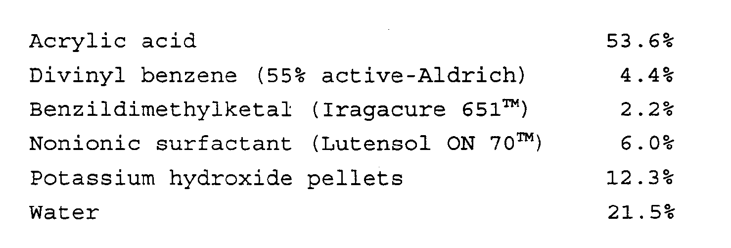
- Once impregnated with this solution, the matrix was passed between two parallel water cooled medium pressure mercury vapour UV lamps to cause the acrylic acid within the pores of the matrix to polymerise and to react with the divinyl benzene. The distance between each of the lamps and the matrix was about 30cm, and the power of each lamp was about 60 W.cm⁻¹. The matrix was then passed through a tank containing 5% by weight potassium hydroxide at 65°C in order to convert the polymerised acrylic acid into its potassium salt form. Finally, the matrix was passed through a series of tanks containing deionised water, and dried over heated rollers at 80°C.
- The electrode separator so produced was strong and flexible, and had a thickness of 40»m. Table 7 compares the characteristics of the crosslinked separator with a separator prepared using a non-crosslinked matrix. These characteristics were determined according to the methods described in "Characteristics of Separators for Alkaline Silver Oxide Secondary Batteries" AD 447301 US Air Force Manual:

- The barrier characteristics to silver ions were determined in two ways as follows: five layers of the electrode separator, each 12mm by 30mm, were soaked with a non-woven polypropylene absorber (300»m thick) of the same size in 40% by weight potassium hydroxide at 60°C for 24 hours. The layers were then assembled in a laminated construction as shown in the accompanying drawing as a stack on a flat surface with polypropylene absorber at the bottom. A glass tube, 6mm internal diameter, was clamped on top of the six layer stack, using a rubber O-ring to make a liquid tight seal between the top separator and the tube. 4cc of 40% by weight potassium hydroxide was then supplied to the tube, which was then sealed and placed in an air oven at 60°C for 2 hours. Silver oxide (Ag₂0) was then added to cover the top surface of the stack completely. The tube was then resealed, and the assembly returned to the oven at 60°C for 24 hours. The potassium hydroxide and excess solid were then carefully removed and the tube was disassembled. The five separators were then separated, washed with deionised water, and allowed to dry in air. Each layer was visually inspected to determine the number of separator layers which had been penetrated by silver (which appeared as brown colouration). A smaller number of penetrated layers indicated better barrier performance.
- The barrier characteristics to silver ions were also determined by measuring the content of the ions of the third of the separator layers from the stack referred to above, using atomic absorption techniques.
- An electrode separator was produced in a continuous process using two pairs of ultraviolet lamps, a first pair to initiate crosslinking of the polyethylene of the matrix, and the second pair to initiate crosslinking and polymerisation of acrylic acid impregnant. It has been found that the properties of electrode separators made using the batch and continuous process follow one another closely.
- An electrode separator was produced using the microporous polyethylene matrix and the two stage process referred to above. The composition of the impregnant solution was as follows:
- Acrylic Acid
- 50.8%
- Divinylbenzene
- 8.3%
- Benzildimethylketal
- 2.2%
- Nonionic Surfactant
- 10.0%
- Potassium hydroxide pellets
- 11.7%
- Water
- 17.0%
- Compared with the products prepared by the two-stage process described above, the product prepared in this example differs in that the mole ratio of divinyl benzene crosslinking agent to acrylic acid is approximately doubled; as a result, the crosslink density in the acrylic acid will also be increased significantly.
- The electrode separator so produced had the following properties:

- From a comparison of the two sets of data in Table 7 with the date in Table 8, it can be seen that crosslinking of the polyethylene matrix has the advantageous combined result of providing a highly effective barrier to silver ions, comparable with that obtained in the comparative example in which the concentration of crosslinking agent (and therefore also the crosslink density) in the acrylic acid is doubled. However, in addition to this barrier property, the resistance to ionic conduction through the membrane by an ion exchange mechanism is maintained at a level significantly lower than is obtained by increasing the crosslink density in the acrylic acid.
- A length of microporous polyethylene film of thickness 30»m was coated with a photoinitiator by passing the film through a solution consisting of 0.5% by weight benzophenone in acetone, and then allowing the solvent to evaporate. This sensitised film was then passed through the a solution of acrylic acid having the following composition, using a transfer roll system at a speed of 2 m.min⁻¹:

- In this solution, half of the acrylic acid monomer is converted to potassium acrylate by the potassium hydroxide and the copper sulphate is present as a homopolymerisation inhibitor.
- The grafting and crosslinking reactions were initiated simultaneously by passing the impregnated film between two mercury vapour lamps at a speed of 2m.min⁻¹. The distance between each lamp and the film was 15cm, and the power of the lamps was varied to determine the effect on the graft level and the degree of crosslinking. The grafted film was then washed in dilute hydrochloric acid, and then deionised water, in order to remove traces of unreacted monomer, residual copper ions, etc, and then dried in air at 60°C. The gel content of the film was determined by refluxing in toluene whilst the acrylic acid content (that is, the graft level) was calculated by an ion exchange method using potassium hydroxide. The results for each ultraviolet lamp power setting are set out below in Table 9:

- An electrode separator was prepared from a polyethylene film of thickness 30 »m, to which a quantity of acrylic acid had been co-polymerised in the manner described above. This film was impregnated continuously at a speed of 2m.min⁻¹ on a transfer roll system with a solution of the following composition:

- The impregnated film was then passed between two mercury vapour lamps positioned 30cm from the film, whose power output had been set at 60 W.cm⁻¹. After the curing step, the film was washed in 5% potassium hydroxide at 65°C, and then washed again in deionised water. The film was then dried over heated rollers at 80°C. A length of polyethylene film thickness 30»m which had not been crosslinked or subjected to the grafting treatment was also converted into an electrode separator membrane in the manner described above.
- The characteristics of these two types of separator are set out in Table 10 below:

- It is found that the separator which is provided with the layer of grafted polyacrylic acid is wetted by an aqueous electrolyte more quickly than the separator without that feature. Quicker wetting with electrolyte has the advantage that the characteristic internal resistance of a cell in which the separator is used is reached more quickly, allowing the cell to be tested more quickly prior to use.
Claims (24)
- A composite polymer membrane comprising a first polymeric material which defines a porous matrix, and a second polymeric material which at least partially fills, and thereby blocks, the pores of the matrix, at least the first material and preferably each of the first and second materials, being crosslinked.
- A membrane as claimed in claim 1, in which the second material is polymeric, and is formed from a vinyl monomer capable of reacting with an acid or a base to form a salt directly or indirectly.
- A membrane as claimed in claim 2, in which the second material comprises a polymer of an ethylenically unsaturated acid or an ester thereof.
- A membrane as claimed in any one of claims 1 to 3, in which the first material is a polyolefin.
- A membrane as claimed in any one of claims 1 to 4, in which the porous matrix has a structure such as would result from the formation of a film from a blend of the first polymeric material and another material which defines the pores and the subsequent removal of the other material from the film.
- A membrane as claimed in any one of claims 1 to 5, in which the volume of the membrane occupied by the pores is at least about 10%, preferably at least about 30%.
- A membrane as claimed in any one of claims 1 to 6, in which the proportion of the volume of the pores within the matrix of the first material which is filled by the second material is at least about 20%, preferably at least about 75%, especially at least about 95%.
- A membrane as claimed in any one of claims 1 to 7, whose thickness is less that 250»m, preferably less than 200»m, especially less than 100»m.
- A membrane as claimed in any one of claims 1 to 8, which includes a layer of a vinyl monomer capable of reacting with an acid or a base to form a salt directly or indirectly, which is graft-polymerised with the first polymeric material of the porous matrix on a surface thereof.
- A membrane as claimed in claim 9, in which the vinyl monomer on the surface of the matrix comprises an ethylenically unsaturated carboxylic acid or an ester thereof.
- A membrane as claimed in claim 9 or claim 10, in which the second polymeric material in the pores of the matrix and the vinyl monomer on the surface of the matrix are derived from the same monomer material.
- A method of making a composite polymer membrane, which comprises:(a) providing a porous matrix defined by a first polymeric material, which is impregnated with a first reagant which, on exposure to an appropriate treatment, leads to crosslinking of the first polymeric material;(b) causing the first polymeric material and the first reagant to react so as to crosslink the first polymeric material; and(c) impregnating the porous matrix with a curable second material so that the second material at least partially fills, and thereby blocks, the pores of the matrix.
- A method as claimed in claim 12, in which the second material is impregnated into the matrix as a component of a mixture, together with a second reagant which, on exposure to an appropriate treatment, leads to crosslinking of the second material; the method including the step of causing the second material to react with the second reagant.
- A method as claimed in claim 13, in which at least one of the crosslinking reactions is initiated by irradiation.
- A method as claimed in claim 14, in which ultraviolet irradiation is used.
- A method as claimed in any one of claims 12 to 15, in which the second material is impregnated in the pores of the matrix of the first material while in solution.
- A method as claimed in any one of claims 12 to 16, which includes the step of forming the porous matrix of the first polymeric material by removal of a pore forming material.
- A method as claimed in any one of claims 12 to 17, which includes the step of graft copolymerising a vinyl monomer capable of reacting with an acid or a base to form a salt directly or indirectly, with first polymeric material on the surface of the porous matrix.
- A method as claimed in claim 18, in which the vinyl monomer is applied to the surface of the matrix in solution, the solution including a component by which homopolymerisation of the monomer is inhibited.
- A method as claimed in claim 19, in which the homopolymerisation inhibitor is an iron (II) salt or a copper (II) salt, preferably iron (II) sulphate.
- A method as claimed in claim 12, in which the polymeric material of the matrix comprises a polyolefin, which includes crosslinking the polymeric material by a process which comprises:(a) impregnating the matrix with a solution of reagant which on exposure to an appropriate treatment leads to crosslinking of the material;(b) removing the solvent in which the reagant is dissolved by volatilising it; and(c) treating the reagant to cause crosslinking of the material.
- A method as claimed in claim 21, in which the crosslinking reaction is initiated by exposure of the impregnated matrix to ultraviolet radiation.
- A method as claimed in claim 21 or claim 22, in which the material of the polymer matrix is polyethylene.
- An electrochemical device which comprises an anode, a cathode, a liquid electrolyte, and an electrode separator comprising a composite polymer membrane as claimed in any one of claims 1 to 11.
Applications Claiming Priority (5)
| Application Number | Priority Date | Filing Date | Title |
|---|---|---|---|
| GB909020580A GB9020580D0 (en) | 1990-09-20 | 1990-09-20 | Polymer membranes |
| GB9020580 | 1990-09-20 | ||
| GB9114762 | 1991-07-09 | ||
| GB919114762A GB9114762D0 (en) | 1991-07-09 | 1991-07-09 | Polymer membrane |
| PCT/GB1991/001604 WO1992005595A1 (en) | 1990-09-20 | 1991-09-19 | Polymer membrane |
Publications (2)
| Publication Number | Publication Date |
|---|---|
| EP0549670A1 EP0549670A1 (en) | 1993-07-07 |
| EP0549670B1 true EP0549670B1 (en) | 1995-11-29 |
Family
ID=26297680
Family Applications (1)
| Application Number | Title | Priority Date | Filing Date |
|---|---|---|---|
| EP91916836A Expired - Lifetime EP0549670B1 (en) | 1990-09-20 | 1991-09-19 | Polymer membrane |
Country Status (6)
| Country | Link |
|---|---|
| US (1) | US5425865A (en) |
| EP (1) | EP0549670B1 (en) |
| JP (1) | JPH06505756A (en) |
| CA (1) | CA2090970A1 (en) |
| DE (1) | DE69115050T2 (en) |
| WO (1) | WO1992005595A1 (en) |
Families Citing this family (42)
| Publication number | Priority date | Publication date | Assignee | Title |
|---|---|---|---|---|
| US5773098A (en) * | 1991-06-20 | 1998-06-30 | British Technology Group, Ltd. | Applying a fluoropolymer film to a body |
| JPH06302314A (en) * | 1993-04-01 | 1994-10-28 | Wr Grace & Co Connecticut | Battery separator |
| AU6491494A (en) * | 1993-04-07 | 1994-10-24 | Rexham Industries Corp. | Method of coating microporous membranes and resulting products |
| US5627217A (en) * | 1993-06-29 | 1997-05-06 | Minnesota Mining And Manufacturing Company | Interfacial polymerization in a porous substrate and substrates functionalized with photochemical groups |
| IL109840A (en) * | 1993-06-29 | 1998-02-22 | Minnesota Mining & Mfg | Interfacial polymerization in a porous substrate and substrates functionalized with photochemical groups |
| US6254978B1 (en) * | 1994-11-14 | 2001-07-03 | W. L. Gore & Associates, Inc. | Ultra-thin integral composite membrane |
| US5547551A (en) | 1995-03-15 | 1996-08-20 | W. L. Gore & Associates, Inc. | Ultra-thin integral composite membrane |
| US6054230A (en) * | 1994-12-07 | 2000-04-25 | Japan Gore-Tex, Inc. | Ion exchange and electrode assembly for an electrochemical cell |
| AU676971B1 (en) * | 1995-08-24 | 1997-03-27 | Dainichiseika Color & Chemicals Mfg. Co. Ltd. | Production process of connected microgel particles and articles treated with connected microgel particles |
| US5643689A (en) * | 1996-08-28 | 1997-07-01 | E.C.R.-Electro-Chemical Research Ltd. | Non-liquid proton conductors for use in electrochemical systems under ambient conditions |
| US6258276B1 (en) * | 1996-10-18 | 2001-07-10 | Mcmaster University | Microporous membranes and uses thereof |
| JP3216592B2 (en) * | 1997-04-23 | 2001-10-09 | 松下電器産業株式会社 | Alkaline storage battery |
| US6605679B1 (en) * | 1997-07-23 | 2003-08-12 | E. I. Du Pont De Nemours And Company | Polymerization of olefins |
| US6635384B2 (en) * | 1998-03-06 | 2003-10-21 | Gore Enterprise Holdings, Inc. | Solid electrolyte composite for electrochemical reaction apparatus |
| WO1999044245A1 (en) | 1998-02-24 | 1999-09-02 | Ramot University Authority For Applied Research & Industrial Development Ltd. | Ion conductive matrixes and their use |
| EP1073131B1 (en) * | 1999-07-30 | 2011-03-16 | Japan Vilene Company, Ltd. | Alkaline battery separator and process for producing the same |
| EP1265748A4 (en) | 1999-10-29 | 2003-06-18 | Hollingsworth & Vose Co | Graft polymerization, separators, and batteries including the separators |
| US6955865B2 (en) * | 1999-10-29 | 2005-10-18 | Hollingsworth & Vose Company | Graft polymerization, separators, and batteries including the separators |
| JP4206182B2 (en) * | 1999-12-27 | 2009-01-07 | 日東電工株式会社 | Microporous film |
| FR2810259B1 (en) * | 2000-06-14 | 2002-08-30 | Univ Toulouse | METHOD FOR MANUFACTURING A NANOFILTRATION MEMBRANE, AND MEMBRANE OBTAINED |
| EP1373382A2 (en) * | 2001-02-22 | 2004-01-02 | Honeywell International Inc. | Nanoporous low dielectric constant polymers |
| US6689501B2 (en) | 2001-05-25 | 2004-02-10 | Ballard Power Systems Inc. | Composite ion exchange membrane for use in a fuel cell |
| EP1448628A2 (en) * | 2001-11-16 | 2004-08-25 | E.I. Du Pont De Nemours And Company | Copolymers of olefins and vinyl- and allylsilanes |
| US6878486B2 (en) * | 2001-12-20 | 2005-04-12 | Eveready Battery Company, Inc. | Seal for electrochemical cell |
| JP4073241B2 (en) * | 2002-04-26 | 2008-04-09 | 旭化成ケミカルズ株式会社 | Battery separator made of polyethylene microporous membrane |
| KR101113201B1 (en) | 2003-02-19 | 2012-04-12 | 나트릭스 세퍼레이션즈, 인코포레이티드 | Composite materials comprising supported porous gels |
| US20040247976A1 (en) * | 2003-06-06 | 2004-12-09 | Steven Holdcroft | Electrochemical cell and fuel cell with curable perfluoro-sulfonate |
| US20040247977A1 (en) * | 2003-06-06 | 2004-12-09 | Steven Holdcroft | Electrochemical cell and fuel cell with curable liquid electrolyte |
| US20040258990A1 (en) * | 2003-06-19 | 2004-12-23 | Mclean Gerard Francis | Electrochemical cell with curable liquid electrolyte and method of making |
| US20040259001A1 (en) * | 2003-06-19 | 2004-12-23 | Mclean Gerard Francis | Method of making an electrochemical cell |
| KR100994124B1 (en) * | 2006-01-19 | 2010-11-15 | 삼성에스디아이 주식회사 | Polymer membrane, its manufacturing method and fuel cell employing the same |
| US8173713B2 (en) * | 2006-05-25 | 2012-05-08 | Drexel University | Filled nanoporous polymer membrane composites for protective clothing and methods for making them |
| JP5270968B2 (en) * | 2008-06-04 | 2013-08-21 | 三井化学株式会社 | Conductive film and method for producing the conductive film |
| WO2010021601A1 (en) * | 2008-08-22 | 2010-02-25 | Agency For Science, Technology And Research | Manufacturing and use of composite scaffolds |
| AU2009288234B2 (en) | 2008-09-02 | 2014-08-21 | Merck Millipore Ltd. | Chromatography membranes, devices containing them, and methods of use thereof |
| ES2968249T3 (en) | 2011-05-17 | 2024-05-08 | Merck Millipore Ltd | Device with layered tubular membranes for chromatography |
| EP3446775A1 (en) | 2013-12-30 | 2019-02-27 | 3M Innovative Properties Co. | Composite membranes and methods of use |
| WO2017004492A1 (en) | 2015-07-01 | 2017-01-05 | 3M Innovative Properties Company | Pvp- and/or pvl-containing composite membranes and methods of use |
| CN107921370B (en) | 2015-07-01 | 2022-03-29 | 3M创新有限公司 | Polymeric ionomer separation membranes and methods of use thereof |
| CN107847867B (en) | 2015-07-01 | 2021-06-25 | 3M创新有限公司 | Composite membranes with improved properties and/or durability and methods of using the same |
| CA3105755C (en) * | 2018-07-31 | 2023-08-01 | Brent Bell | Polyethylene film |
| CN120273192B (en) * | 2025-04-03 | 2025-11-28 | 桂阳县安涵服饰有限公司 | A toughened thin-film composite fabric and its preparation method |
Family Cites Families (21)
| Publication number | Priority date | Publication date | Assignee | Title |
|---|---|---|---|---|
| US2965697A (en) * | 1956-11-05 | 1960-12-20 | Electric Storage Battery Co | Battery diaphragm |
| US3376168A (en) * | 1962-08-02 | 1968-04-02 | Yardney International Corp | Metal-containing graft-polymerized product and method of making same |
| GB1039444A (en) * | 1963-07-24 | 1966-08-17 | Ca Atomic Energy Ltd | Radiation induced graft copolymerization |
| US3427206A (en) * | 1965-02-26 | 1969-02-11 | Rai Res Corp | Separator for alkaline cells |
| US3673127A (en) * | 1969-10-20 | 1972-06-27 | Gen Electric | Ultrafine porous polymer article and method of making |
| GB1372225A (en) * | 1971-01-07 | 1974-10-30 | Zlehit Pri Ban | Ionically conducting membrane suitable for use as a separator in an alkaline cell |
| GB1449814A (en) * | 1972-07-18 | 1976-09-15 | Atomic Energy Authority Uk | Method of preparing porous material0synthetic polymer composites |
| JPS568645B2 (en) * | 1974-09-05 | 1981-02-25 | ||
| GB1512553A (en) * | 1974-09-19 | 1978-06-01 | Mitsubishi Petrochemical Co | Orthopedic material |
| GB1538810A (en) * | 1976-08-10 | 1979-01-24 | Sumitomo Electric Industries | Hydrophilic porous fluorocarbon structures and process for their production |
| US4230463A (en) * | 1977-09-13 | 1980-10-28 | Monsanto Company | Multicomponent membranes for gas separations |
| JPS53106134A (en) * | 1977-02-28 | 1978-09-14 | Canon Inc | Power source |
| USRE31824E (en) * | 1977-05-31 | 1985-02-05 | Rai Research Corporation | Separator membranes for electrochemical cells |
| EP0004237A1 (en) * | 1978-03-14 | 1979-09-19 | Elf Atochem S.A. | Ion exchange membranes; their preparation and their use in the electrolysis of sodium chloride |
| US4346142A (en) * | 1979-09-04 | 1982-08-24 | Celanese Corporation | Hydrophilic monomer treated microporous films and process |
| FR2505879B1 (en) * | 1981-05-15 | 1985-09-27 | Chloe Chemie | DIAPHRAGM, ITS PREPARATION METHOD AND THE ELECTROLYSIS METHOD USING THE SAME |
| US4468441A (en) * | 1981-10-01 | 1984-08-28 | Rai Research Corp. | Separator membranes for redox-type electrochemical cells |
| US4969998A (en) * | 1984-04-23 | 1990-11-13 | W. L. Gore & Associates, Inc. | Composite semipermeable membrane |
| US4613544A (en) * | 1984-12-04 | 1986-09-23 | Minnesota Mining And Manufacturing Co. | Waterproof, moisture-vapor permeable sheet material and method of making the same |
| GB8608430D0 (en) * | 1986-04-07 | 1986-05-14 | Raychem Ltd | Porous polymer article |
| US4804598A (en) * | 1987-12-14 | 1989-02-14 | Westinghouse Electric Corp. | Separator systems for silver-iron batteries |
-
1991
- 1991-09-19 EP EP91916836A patent/EP0549670B1/en not_active Expired - Lifetime
- 1991-09-19 DE DE69115050T patent/DE69115050T2/en not_active Expired - Lifetime
- 1991-09-19 US US08/027,157 patent/US5425865A/en not_active Expired - Lifetime
- 1991-09-19 JP JP3515272A patent/JPH06505756A/en active Pending
- 1991-09-19 CA CA2090970A patent/CA2090970A1/en not_active Abandoned
- 1991-09-19 WO PCT/GB1991/001604 patent/WO1992005595A1/en not_active Ceased
Also Published As
| Publication number | Publication date |
|---|---|
| JPH06505756A (en) | 1994-06-30 |
| DE69115050T2 (en) | 1996-08-01 |
| CA2090970A1 (en) | 1992-04-02 |
| DE69115050D1 (en) | 1996-01-11 |
| US5425865A (en) | 1995-06-20 |
| WO1992005595A1 (en) | 1992-04-02 |
| EP0549670A1 (en) | 1993-07-07 |
Similar Documents
| Publication | Publication Date | Title |
|---|---|---|
| EP0549670B1 (en) | Polymer membrane | |
| EP0593612B1 (en) | Polymeric sheet | |
| EP0263159B1 (en) | Composite membrane | |
| US5256503A (en) | Process for making a composite membrane | |
| Ishigaki et al. | Graft polymerization of acrylic acid onto polyethylene film by preirradiation method. I. Effects of preirradiation dose, monomer concentration, reaction temperature, and film thickness | |
| HK1000833B (en) | Polymeric sheet | |
| KR100999048B1 (en) | Method for preparing anion exchange composite membrane containing styrene-vinylbenzyl copolymer | |
| FR2489598A1 (en) | GRAFTING PROCESS USING GAMMA RAYS TO PREPARE SEPARATION MEMBRANES FOR ELECTROCHEMICAL CELLS | |
| JPS5924491B2 (en) | Membrane for battery separator | |
| CA2772306A1 (en) | Ion exchange membranes featuring polymer-filled microporous supports | |
| JP2005539117A (en) | Process for making graft copolymers useful in membranes | |
| EP0014459B1 (en) | Process for production of separators for use in cells | |
| US6849688B2 (en) | Polymer grafted support polymers | |
| EP1257348A1 (en) | Graft polymeric membranes and ion-exchange membranes formed therefrom | |
| JP3101058B2 (en) | Battery separator | |
| WO2006131758A2 (en) | Membrane electrode assemblies and their production | |
| JPS6329694B2 (en) | ||
| JPS6217822B2 (en) | ||
| JPS5810368A (en) | Battery separator and its manufacture |
Legal Events
| Date | Code | Title | Description |
|---|---|---|---|
| PUAI | Public reference made under article 153(3) epc to a published international application that has entered the european phase |
Free format text: ORIGINAL CODE: 0009012 |
|
| 17P | Request for examination filed |
Effective date: 19930325 |
|
| AK | Designated contracting states |
Kind code of ref document: A1 Designated state(s): DE FR GB |
|
| 17Q | First examination report despatched |
Effective date: 19940614 |
|
| GRAA | (expected) grant |
Free format text: ORIGINAL CODE: 0009210 |
|
| AK | Designated contracting states |
Kind code of ref document: B1 Designated state(s): DE FR GB |
|
| REF | Corresponds to: |
Ref document number: 69115050 Country of ref document: DE Date of ref document: 19960111 |
|
| ET | Fr: translation filed | ||
| PLBE | No opposition filed within time limit |
Free format text: ORIGINAL CODE: 0009261 |
|
| STAA | Information on the status of an ep patent application or granted ep patent |
Free format text: STATUS: NO OPPOSITION FILED WITHIN TIME LIMIT |
|
| 26N | No opposition filed | ||
| REG | Reference to a national code |
Ref country code: GB Ref legal event code: IF02 |
|
| REG | Reference to a national code |
Ref country code: GB Ref legal event code: 732E |
|
| REG | Reference to a national code |
Ref country code: FR Ref legal event code: TP |
|
| PGFP | Annual fee paid to national office [announced via postgrant information from national office to epo] |
Ref country code: GB Payment date: 20090916 Year of fee payment: 19 |
|
| PGFP | Annual fee paid to national office [announced via postgrant information from national office to epo] |
Ref country code: DE Payment date: 20090917 Year of fee payment: 19 |
|
| PGFP | Annual fee paid to national office [announced via postgrant information from national office to epo] |
Ref country code: FR Payment date: 20091012 Year of fee payment: 19 |
|
| GBPC | Gb: european patent ceased through non-payment of renewal fee |
Effective date: 20100919 |
|
| REG | Reference to a national code |
Ref country code: FR Ref legal event code: ST Effective date: 20110531 |
|
| REG | Reference to a national code |
Ref country code: DE Ref legal event code: R119 Ref document number: 69115050 Country of ref document: DE Effective date: 20110401 |
|
| PG25 | Lapsed in a contracting state [announced via postgrant information from national office to epo] |
Ref country code: DE Free format text: LAPSE BECAUSE OF NON-PAYMENT OF DUE FEES Effective date: 20110401 Ref country code: FR Free format text: LAPSE BECAUSE OF NON-PAYMENT OF DUE FEES Effective date: 20100930 |
|
| PG25 | Lapsed in a contracting state [announced via postgrant information from national office to epo] |
Ref country code: GB Free format text: LAPSE BECAUSE OF NON-PAYMENT OF DUE FEES Effective date: 20100919 |