EP0549237A2 - Optical disk storage system and head apparatus therefor - Google Patents
Optical disk storage system and head apparatus therefor Download PDFInfo
- Publication number
- EP0549237A2 EP0549237A2 EP92311429A EP92311429A EP0549237A2 EP 0549237 A2 EP0549237 A2 EP 0549237A2 EP 92311429 A EP92311429 A EP 92311429A EP 92311429 A EP92311429 A EP 92311429A EP 0549237 A2 EP0549237 A2 EP 0549237A2
- Authority
- EP
- European Patent Office
- Prior art keywords
- optical
- optical head
- head apparatus
- slider
- storage medium
- Prior art date
- Legal status (The legal status is an assumption and is not a legal conclusion. Google has not performed a legal analysis and makes no representation as to the accuracy of the status listed.)
- Granted
Links
Images


Classifications
-
- G—PHYSICS
- G11—INFORMATION STORAGE
- G11B—INFORMATION STORAGE BASED ON RELATIVE MOVEMENT BETWEEN RECORD CARRIER AND TRANSDUCER
- G11B11/00—Recording on or reproducing from the same record carrier wherein for these two operations the methods are covered by different main groups of groups G11B3/00 - G11B7/00 or by different subgroups of group G11B9/00; Record carriers therefor
- G11B11/10—Recording on or reproducing from the same record carrier wherein for these two operations the methods are covered by different main groups of groups G11B3/00 - G11B7/00 or by different subgroups of group G11B9/00; Record carriers therefor using recording by magnetic means or other means for magnetisation or demagnetisation of a record carrier, e.g. light induced spin magnetisation; Demagnetisation by thermal or stress means in the presence or not of an orienting magnetic field
- G11B11/105—Recording on or reproducing from the same record carrier wherein for these two operations the methods are covered by different main groups of groups G11B3/00 - G11B7/00 or by different subgroups of group G11B9/00; Record carriers therefor using recording by magnetic means or other means for magnetisation or demagnetisation of a record carrier, e.g. light induced spin magnetisation; Demagnetisation by thermal or stress means in the presence or not of an orienting magnetic field using a beam of light or a magnetic field for recording by change of magnetisation and a beam of light for reproducing, i.e. magneto-optical, e.g. light-induced thermomagnetic recording, spin magnetisation recording, Kerr or Faraday effect reproducing
- G11B11/1055—Disposition or mounting of transducers relative to record carriers
- G11B11/1058—Flying heads
-
- G—PHYSICS
- G11—INFORMATION STORAGE
- G11B—INFORMATION STORAGE BASED ON RELATIVE MOVEMENT BETWEEN RECORD CARRIER AND TRANSDUCER
- G11B11/00—Recording on or reproducing from the same record carrier wherein for these two operations the methods are covered by different main groups of groups G11B3/00 - G11B7/00 or by different subgroups of group G11B9/00; Record carriers therefor
- G11B11/10—Recording on or reproducing from the same record carrier wherein for these two operations the methods are covered by different main groups of groups G11B3/00 - G11B7/00 or by different subgroups of group G11B9/00; Record carriers therefor using recording by magnetic means or other means for magnetisation or demagnetisation of a record carrier, e.g. light induced spin magnetisation; Demagnetisation by thermal or stress means in the presence or not of an orienting magnetic field
- G11B11/105—Recording on or reproducing from the same record carrier wherein for these two operations the methods are covered by different main groups of groups G11B3/00 - G11B7/00 or by different subgroups of group G11B9/00; Record carriers therefor using recording by magnetic means or other means for magnetisation or demagnetisation of a record carrier, e.g. light induced spin magnetisation; Demagnetisation by thermal or stress means in the presence or not of an orienting magnetic field using a beam of light or a magnetic field for recording by change of magnetisation and a beam of light for reproducing, i.e. magneto-optical, e.g. light-induced thermomagnetic recording, spin magnetisation recording, Kerr or Faraday effect reproducing
- G11B11/1055—Disposition or mounting of transducers relative to record carriers
- G11B11/10552—Arrangements of transducers relative to each other, e.g. coupled heads, optical and magnetic head on the same base
- G11B11/10554—Arrangements of transducers relative to each other, e.g. coupled heads, optical and magnetic head on the same base the transducers being disposed on the same side of the carrier
-
- G—PHYSICS
- G11—INFORMATION STORAGE
- G11B—INFORMATION STORAGE BASED ON RELATIVE MOVEMENT BETWEEN RECORD CARRIER AND TRANSDUCER
- G11B7/00—Recording or reproducing by optical means, e.g. recording using a thermal beam of optical radiation by modifying optical properties or the physical structure, reproducing using an optical beam at lower power by sensing optical properties; Record carriers therefor
- G11B7/12—Heads, e.g. forming of the optical beam spot or modulation of the optical beam
- G11B7/122—Flying-type heads, e.g. analogous to Winchester type in magnetic recording
Definitions
- the present invention relates generally to optical disk storage systems and optical head apparatus therefor.
- an information bit is stored by focusing a magnetic field to a small volume on the disk to align the magnetic domains in that volume to a desired orientation.
- an information bit is stored by focusing a laser beam onto a small spot on the optical disk to heat the medium and thus effect a physical change in the medium material at that spot.
- the heat generated by the laser beam causes the magnetic domains at the spot location to be aligned with an applied magnetic field.
- the demand for increased storage capacity is presently being met by increasing the areal bit density on the storage disk.
- the magnetic write transducer (head) gap length the thickness of the magnetic storage media and the head to disk separation.
- the smaller the head-disk separation i.e., the lower the head flying height, the smaller the bit cell size which can be achieved.
- the limit of lower flying height is contact recording, in which the slider is in physical contact with the rotating magnetic disk, i.e., the slider is sliding or rubbing continuously on the disk surface and the read/write transducer is as close as the edge of the slider can be to the disk surface.
- a laser beam is projected onto the optical storage medium (optical disk) and focused to a small spot on the disk surface through an optical transducer or head.
- the optical head is maintained well above the medium surface and the beam spot size is defined by the laser light wavelength ( ⁇ ) and conventional optics.
- ⁇ the laser light wavelength
- conventional optics It has been generally believed that the diffraction limit in air of about ⁇ /1.5 is the fundamental lower bound in resolution for any optical image recording.
- the beam output of injection lasers presently in use have wavelengths on the order of 1 micrometer ( ⁇ m). New lasers which use second or higher order harmonics and frequency multipliers are currently being explored. However, considerable difficulty is being encountered and the likelihood of development of new lasers having suitable characteristics in the near future is low. On the other hand, there has been steady improvement in the reliability and power capabilities of the currently used conventional semiconductor lasers which is likely to continue due to their wide use.
- a typical prior art optical disk storage system comprises a fixed optical element and a movable optical element generally referred to as the optical head.
- the optical head includes such components as an objective lens, one or more mirrors, a focus actuator motor and a fine tracking actuator.
- the optical head is mounted in a carriage which rides on a pair of rails for radial motion across the disk.
- the carriage will provide mountings for coarse tracking actuator coils and also include a set of wheels which engage the rails.
- the mass and size of the optical head and carriage combination are principal contributors to the relatively long access times encountered in optical disk drive systems.
- the present invention seeks to overcome the disadvantages of prior optical disk storage systems and accordingly provides optical head apparatus for use with a rotatable optical storage medium, comprising: focusing means for focusing a light beam onto an optical storage medium; and support means maintained in physical contact with said optical storage medium, said focusing means being rigidly mounted on said support means in close proximity to a major surface of said optical storage medium.
- the invention provides an optical storage system comprising an optical storage medium comprising a rigid substrate having a layer of optical storage material thereon; an optical head apparatus as claimed in the appended claims, an optical head of the apparatus comprising a substrate of a material having a load versus friction characteristic that is nonlinear in the negative load region; and means coupled to said optical storage medium for producing relative motion between said optical storage medium and said optical head up to a selected operating speed sufficient to generate a restoring force responsive to said load versus friction characteristics of said optical head substrate, said restoring force having a magnitude sufficient for maintaining said optical head in substantially physical contact with said optical storage medium at said selected operating speed, whereby data can be written or sensed without excessive wear to either said optical head or said optical storage medium.
- the relative motion between the optical slider and the optical disk generates a tribo-attractive force which maintains a very steady average slider-disk separation, fluctuating within only several nanometers (nm) with respect to the disk surface. Since the slider is in contact with the disk surface, the focal length of the objective lens is dictated only by the thickness of the transparent protective layers over the recording layer, i.e., the optical medium, of the optical disk, thus greatly reducing the focal length for the objective lens.
- the objective lens is fixedly mounted on the slider and is maintained at an essentially constant separation from the optical media with the same degree of accuracy with which the slider itself is maintained from the disk surface.
- a focusing servo system is eliminated.
- the end result is a much smaller, lighter optical slider having few optical components suspended from a linear or radial access arm.
- Both coarse and fine tracking actuator functions may be combined in a single access arm actuator, such as a voice coil motor, with all controller functions implemented in a single actuator controller.
- the present invention provides an optical disk drive system from which the focus servo system has been eliminated and which achieves data access times comparable to access times available with present day magnetic disk storage systems.
- Reduction of the objective lens focal distance allows lenses having higher numerical aperture to be used, thus providing much tighter focus of the laser beam and achieving increased areal bit density. Additionally, the elimination of the servo-mechanical systems for focusing greatly simplifies the system and reduces both the mass and size of the optical head. The smaller, less massive head reduces access time and makes feasible the stacking of optical disks to provide increased volume density.
- the optical head comprises a plano convex objective lens mounted on a slider such that its flat surface is essentially co-planar with the bearing or bottom surface of the slider.
- the very small separation, a small fraction of the laser wavelength, between the flat bottom surface of the focusing optics and the optical disk overcoat layer, i.e., the recording layer protective layer, allows relatively efficient transmission of the laser beam power. If materials having a high refractive index are used for the disk overcoat and the focusing optics, the laser beam wavelength will be reduced, thus improving the optical resolution and providing increased areal bit density.
- an information storage system comprising at least one rigid storage disk 12 fixedly supported on a spindle 17 and rotated by a disk drive motor (not shown).
- the recording medium 11 is deposited on the disk in a well-known manner in the form of an annular pattern of concentric data tracks, for example.
- the storage medium is covered by a protective layer such as a carbon or zirconia overcoat.
- At least one slider 13 is positioned in contact with the protective overcoat layer at the disk surface and supports one or more read/write heads.
- the slider 13 is attached to an actuator arm 19 by means of a suspension 15.
- the actuator arm 19 is attached to an accessing mechanism such as a voice coil motor (not shown) for positioning the read/write heads over desired data tracks.
- the slider 13 is moved radially across the disk so that the read/write head may access different portions of the disk surface 11.
- the slider 13 is positioned by the suspension arm 15 so that it is in contact with the recording medium at normal operating speed produced by relative motion between the slider 13 and the disk surface 11 in the direction indicated by arrow 16. It is a feature of the present invention that the slider 13 remains in direct physical contact with the disk surface 11 even when the relative motion between the slider and disk surface exceeds speeds of 20 meters per second. Physical contact is maintained by an attractive force, referred to as a tribo-attractive force, which is of sufficient strength to overcome the lifting force created by the film of air which is moving with the disk surface which tends to force the slider away from the disk surface.
- U.S. Patent No. 4,819,091 discloses in detail a magnetic disk storage system incorporating a slider in physical contact with the storage medium.
- the tribo-attractive force is due to the coulombic attraction between the tribo-electric charge generated as a result of relative motion between the slider and disk surfaces when in physical contact.
- the tribo-electric force is relatively independent of the disk speed above some threshold speed of the order of one meters per second but decreases below this speed. As the speed is reduced, there is a point at which the tribo-attractive force is no longer sufficient to maintain the slider in contact with the disk surface. This point of release appears to be a function of the disk run out and surface roughness. Additionally, as the suspension arm loading, i.e., the external load, on the slider 13 is decreased to a negative load, a "restoring force" is generated.
- an optical slider 31 comprising an objective lens mounted on a crystalline slider in physical contact with the surface of an optical disk is shown.
- Suitable slider materials exhibiting the described tribo-attractive characteristics may generally be selected from a range of crystalline and amorphous materials having a low coefficient of friction and which are electrically non-conductive. While materials also exhibiting a high thermal conductivity are preferred, a high thermal conductivity does not appear to be required in all materials which exhibit the tribo-attractive effect.
- the optical slider may comprise a simple plano-convex objective lens 33 mounted on a single crystal sapphire slider. Other suitable slider materials including diamond are described in US 4,819,091.
- the optical disk may have the conventional structure of a transparent substrate layer 34 and a thin film optical media 36 on the inner surface of the transparent layer.
- the outside or upper surface of the transparent substrate layer 34 is coated with a hard, transparent and conducting protective overlayer 32 such as an amorphous carbon film or a zirconium oxide (ZrO2).
- a hard, transparent and conducting protective overlayer 32 such as an amorphous carbon film or a zirconium oxide (ZrO2).
- ZrO2 zirconium oxide
- Presently commercially available thin film disks are obtainable having protective coatings of hard amorphous carbon of approximately 30nm thick. Additionally, the surface of the disks are textured with a roughness of approximately 40nm.
- any focusing optics may be positioned within less than 80nm (including the overcoat 32 thickness) of optical disk surface, a small fraction of the wavelength of currently utilized semiconductor lasers, and maintain this position without the requirement of prior art electro mechanical servo mechanisms. With smooth disk and slider surfaces and decreased overcoat layer thickness
- the MO system 40 basically comprises a semiconductor laser 43, including collimating optics, generating a collimated laser beam 44, beam polarizing means 45, a beam splitter 47, a rigid suspension arm 49 supporting an optical slider 51 in physical contact with the surface of a rotatable optical disk 53, and motor means 55 coupled to the optical disk 53.
- the reflected or return beam 48 is separated out at the beam splitter 47 and directed to a detector circuit 59 via beam analyzer means 57.
- the optical disk 53 has a conventional structure, as described above with reference to Fig.
- a transparent substrate layer with a thin film optical medium layer on the inner or lower surface with a reflective overcoat layer comprising a transparent substrate layer with a thin film optical medium layer on the inner or lower surface with a reflective overcoat layer.
- the outside or upper surface of the transparent substrate layer is coated with a conducting hard protective overcoat layer which is grounded to bleed off the tribo-electric charge generated by the relative motion between the slider and the disk surfaces.
- the hard amorphous carbon film commonly used with commercially available thin film magnetic storage disks is sufficiently conducting and transparent at thicknesses of 30 nm or less for this purpose.
- the optical slider 51 is suspended from the support arm 49 by spring flexures (as shown in Figs. 5 and 7) such that the slider follows the disk surface vertically with surface roughness and disk run out.
- the rigid support arm 49 is mounted on rails 42 and is movable along the radius of the disk 53 such that the slider can access desirable disk tracks.
- the movement of the support arm 49 is coupled to an access mechanism (not shown) such as a voice coil motor, for example.
- the voice coil motor is a coil movable within a fixed magnetic field with the direction and velocity of the coil movement being controlled by optical head positioning circuitry (not shown).
- the optical slider 51 (as shown in Fig.
- an optical slider 51 suitable for use in a magneto-optic (MO) storage system comprises a slider 51 having the objective lens 64 and the magnetic coil 66 mounted concentrically with the objective lens at or near the trailing edge of slider 54 in close proximity to the interface 68 between the slider 51 and the disk 30 surface.
- the objective lens 64 and magnetic coil 66 may be mounted internally in an aperture 75 extending vertically through the slider 51 or in a vertical channel 75 formed in the face of the trailing edge of slider 51.
- the slider 51 is suspended from support arm 49 by a flexure spring suspension 63.
- the slider 51 is positioned relative to support arm 49 such that the lens 64 is aligned with aperture 76 formed lengthwise in support arm 49.
- Laser beam 46 is directed along aperture 76 via mirror 61 and lens 64 to be focused on the magneto-optic media layer 71.
- Laser beam 46 comprises both the transmitted beam 44 and the return beam 48 reflected from reflection layer 73.
- magneto-optic disk 30 comprises a transparent substrate layer 69 having the magneto-optic media layer 71 with a reflective layer 73 on the inner or lower surface and a protective overcoat layer 67 in physical contact with the slider 51.
- a contact slider 51 having a plano-convex objective lens 65 mounted thereon is suspended from the support arm 49 by flexure 63.
- objective lens 65 is positioned to receive laser beam 46 and focus it on the optical media layer 81.
- the optical resolution capability for a laser beam may be significantly increased over the resolution that can be achieved in air. This requires that materials having large refractive index be used for the objective lens 65 as well as for the protective overcoat layer 79.
- the flat bottom surface of the plano-convex objective lens 65 is co-planar with the bottom surface of the slider 51 in order to provide efficient transfer of light energy across the slider/disk interface 68 and to minimize any distortion in the focus.
- the optical disk 80 is similar to a conventional magnetic recording disk and comprises a substrate layer 85, typically of an aluminum alloy or glass having a very smooth upper surface, a reflective thin film layer 83 and an optic or magneto-optic media layer 81.
- the optic media layer 81 is overcoated with a transparent protective layer 79 which forms the disk surface in contact with the slider and is sufficiently thick, approximately 300 or less, to provide chemical insulation and wear protection for the optical media layer.
- the protective overcoat layer 79 is of a high refractive index material. Zirconia (ZrO2) which has a refractive index of about two is a suitable disk coating for tribo-electric contact recording and is commonly used as a protective overcoat layer for magnetic thin film disks.
- ZrO2 Zirconia
- Other examples of suitable hard materials having high refractive index are rutile (2.5), diamond (2.4), GaAs (3.3), SrTiO3 (2.3) and Fe2O3 (3.2).
- a composite optical slider comprising an integrated optical head 82 mounted on or embedded in a contact slider 92.
- Optical fiber 95 couples the transmission beam to the slider 92 for further coupling via polarizing means 84 and mirror 86 to the objective lens 91 for focusing at the media layer 83.
- the reflected beam is coupled via the objective lens 91, beam splitter 89, beam analyzer means 88 and optical fiber 93 to the detector circuitry (not shown).
- Utilizing optical fibers 93, 95 with integrated optical elements including the polarizing means 84, mirror 86, beam splitter 89 and beam analyzer 88 reduces the complexity of the optical apparatus and allows precise optical alignment with the objective lens to be achieved.
- a suitable optical disk comprises disk substrate 85 having a reflective layer 83, the optical recording media layer 81 and protective overcoat layer 79 deposited thereon.
Landscapes
- Physics & Mathematics (AREA)
- Optics & Photonics (AREA)
- Optical Head (AREA)
- Optical Recording Or Reproduction (AREA)
Abstract
Description
- The present invention relates generally to optical disk storage systems and optical head apparatus therefor.
- In magnetic storage systems, an information bit is stored by focusing a magnetic field to a small volume on the disk to align the magnetic domains in that volume to a desired orientation. In optical storage systems, an information bit is stored by focusing a laser beam onto a small spot on the optical disk to heat the medium and thus effect a physical change in the medium material at that spot. In the case of magneto-optic storage systems, the heat generated by the laser beam causes the magnetic domains at the spot location to be aligned with an applied magnetic field. In all moving disk storage systems, the demand for increased storage capacity is presently being met by increasing the areal bit density on the storage disk.
- In magnetic disk storage systems, increase of areal bit density requires the reduction of three basic parameters, the magnetic write transducer (head) gap length, the thickness of the magnetic storage media and the head to disk separation. Given a specified gap length and media thickness, the smaller the head-disk separation, i.e., the lower the head flying height, the smaller the bit cell size which can be achieved. The limit of lower flying height is contact recording, in which the slider is in physical contact with the rotating magnetic disk, i.e., the slider is sliding or rubbing continuously on the disk surface and the read/write transducer is as close as the edge of the slider can be to the disk surface.
- In an optical storage system, a laser beam is projected onto the optical storage medium (optical disk) and focused to a small spot on the disk surface through an optical transducer or head. In prior art optical systems, the optical head is maintained well above the medium surface and the beam spot size is defined by the laser light wavelength (λ) and conventional optics. It has been generally believed that the diffraction limit in air of about λ/1.5 is the fundamental lower bound in resolution for any optical image recording. Thus, the primary means of increasing areal bit density in an optical or magneto-optical system has traditionally been to utilize laser beams of shorter wavelength. The beam output of injection lasers presently in use have wavelengths on the order of 1 micrometer (µm). New lasers which use second or higher order harmonics and frequency multipliers are currently being explored. However, considerable difficulty is being encountered and the likelihood of development of new lasers having suitable characteristics in the near future is low. On the other hand, there has been steady improvement in the reliability and power capabilities of the currently used conventional semiconductor lasers which is likely to continue due to their wide use.
- To achieve high density optical recording at or near the diffraction limit utilizing conventional semiconductor lasers it is necessary to very tightly focus the laser beam. This requires high numerical aperture objective lens which means that the lens must be maintained very precisely at the focal distance from the optical medium. Typically, focus is accomplished by an electro-mechanical servo system which maintains the optical head at the required distance from the medium thus adding to the mass and size of the optical head. Alternatively, in systems which do not physically adjust the distance of the head from the medium, relatively complex focusing systems elsewhere in the system are required to compensate for the varying head height.
- A typical prior art optical disk storage system comprises a fixed optical element and a movable optical element generally referred to as the optical head. The optical head includes such components as an objective lens, one or more mirrors, a focus actuator motor and a fine tracking actuator. The optical head is mounted in a carriage which rides on a pair of rails for radial motion across the disk. Typically, the carriage will provide mountings for coarse tracking actuator coils and also include a set of wheels which engage the rails. The mass and size of the optical head and carriage combination are principal contributors to the relatively long access times encountered in optical disk drive systems.
- The present invention seeks to overcome the disadvantages of prior optical disk storage systems and accordingly provides optical head apparatus for use with a rotatable optical storage medium, comprising:
focusing means for focusing a light beam onto an optical storage medium; and
support means maintained in physical contact with said optical storage medium, said focusing means being rigidly mounted on said support means in close proximity to a major surface of said optical storage medium. - Viewed from another aspect, the invention provides an optical storage system comprising an optical storage medium comprising a rigid substrate having a layer of optical storage material thereon; an optical head apparatus as claimed in the appended claims, an optical head of the apparatus comprising a substrate of a material having a load versus friction characteristic that is nonlinear in the negative load region; and
means coupled to said optical storage medium for producing relative motion between said optical storage medium and said optical head up to a selected operating speed sufficient to generate a restoring force responsive to said load versus friction characteristics of said optical head substrate, said restoring force having a magnitude sufficient for maintaining said optical head in substantially physical contact with said optical storage medium at said selected operating speed, whereby data can be written or sensed without excessive wear to either said optical head or said optical storage medium. - The relative motion between the optical slider and the optical disk generates a tribo-attractive force which maintains a very steady average slider-disk separation, fluctuating within only several nanometers (nm) with respect to the disk surface. Since the slider is in contact with the disk surface, the focal length of the objective lens is dictated only by the thickness of the transparent protective layers over the recording layer, i.e., the optical medium, of the optical disk, thus greatly reducing the focal length for the objective lens.
- In the present invention, the objective lens is fixedly mounted on the slider and is maintained at an essentially constant separation from the optical media with the same degree of accuracy with which the slider itself is maintained from the disk surface. Thus the requirement for a focusing servo system is eliminated. This allows the movable objective lens holder, focus actuator motor, focus servo controller and associated circuitry and other components to be eliminated from the system, resulting in a smaller, less massive optical head and a less complex system with fewer components. The end result is a much smaller, lighter optical slider having few optical components suspended from a linear or radial access arm. Both coarse and fine tracking actuator functions may be combined in a single access arm actuator, such as a voice coil motor, with all controller functions implemented in a single actuator controller. Thus, the present invention provides an optical disk drive system from which the focus servo system has been eliminated and which achieves data access times comparable to access times available with present day magnetic disk storage systems.
- Reduction of the objective lens focal distance allows lenses having higher numerical aperture to be used, thus providing much tighter focus of the laser beam and achieving increased areal bit density. Additionally, the elimination of the servo-mechanical systems for focusing greatly simplifies the system and reduces both the mass and size of the optical head. The smaller, less massive head reduces access time and makes feasible the stacking of optical disks to provide increased volume density.
- An additional increase in areal bit density may be realized by utilizing the well-known principle that the wavelength of light in a medium is reduced by its index of refraction in that medium. In one embodiment of the present invention, the optical head comprises a plano convex objective lens mounted on a slider such that its flat surface is essentially co-planar with the bearing or bottom surface of the slider. The very small separation, a small fraction of the laser wavelength, between the flat bottom surface of the focusing optics and the optical disk overcoat layer, i.e., the recording layer protective layer, allows relatively efficient transmission of the laser beam power. If materials having a high refractive index are used for the disk overcoat and the focusing optics, the laser beam wavelength will be reduced, thus improving the optical resolution and providing increased areal bit density.
- Preferred embodiments of the invention will now be described, by way of example only, with reference to the accompanying drawings, in which:
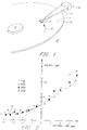
- Fig. 1 is a perspective view of a contact slider supported on a rotating storage disk in accordance with the principles of the present invention;
- Fig. 2 is a graphical diagram illustrating the frictional force versus external load on a selected slider as shown in Fig. 1;
- Fig. 3 is a cross-sectional view of one preferred embodiment of the slider shown in Fig. 1;
- Fig. 4 is a conceptual diagram in perspective of an optical storage system in accordance with the present invention;
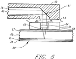
- Fig. 5 is a cross-sectional view of a preferred embodiment of a slider for use in a magneto-optical storage system as shown in Fig. 4;
- Fig. 6 is a cross-sectional view of a preferred embodiment of the slider shown in Fig. 4; and
- Fig. 7 is a cross-sectional view of another preferred embodiment of the slider shown in Fig. 4.
- Referring now to Fig. 1, an information storage system comprising at least one
rigid storage disk 12 fixedly supported on aspindle 17 and rotated by a disk drive motor (not shown). Therecording medium 11 is deposited on the disk in a well-known manner in the form of an annular pattern of concentric data tracks, for example. The storage medium is covered by a protective layer such as a carbon or zirconia overcoat. At least oneslider 13 is positioned in contact with the protective overcoat layer at the disk surface and supports one or more read/write heads. Theslider 13 is attached to anactuator arm 19 by means of asuspension 15. Theactuator arm 19 is attached to an accessing mechanism such as a voice coil motor (not shown) for positioning the read/write heads over desired data tracks. As thestorage disk 12 rotates, theslider 13 is moved radially across the disk so that the read/write head may access different portions of thedisk surface 11. - In accordance with the present invention, the
slider 13 is positioned by thesuspension arm 15 so that it is in contact with the recording medium at normal operating speed produced by relative motion between theslider 13 and thedisk surface 11 in the direction indicated byarrow 16. It is a feature of the present invention that theslider 13 remains in direct physical contact with thedisk surface 11 even when the relative motion between the slider and disk surface exceeds speeds of 20 meters per second. Physical contact is maintained by an attractive force, referred to as a tribo-attractive force, which is of sufficient strength to overcome the lifting force created by the film of air which is moving with the disk surface which tends to force the slider away from the disk surface. U.S. Patent No. 4,819,091 discloses in detail a magnetic disk storage system incorporating a slider in physical contact with the storage medium. - The tribo-attractive force is due to the coulombic attraction between the tribo-electric charge generated as a result of relative motion between the slider and disk surfaces when in physical contact. The tribo-electric force is relatively independent of the disk speed above some threshold speed of the order of one meters per second but decreases below this speed. As the speed is reduced, there is a point at which the tribo-attractive force is no longer sufficient to maintain the slider in contact with the disk surface. This point of release appears to be a function of the disk run out and surface roughness. Additionally, as the suspension arm loading, i.e., the external load, on the
slider 13 is decreased to a negative load, a "restoring force" is generated. That is, when the two surfaces are forced apart, the tribo-attractive force increases to counteract the force urging the two surfaces apart. This restoring force enables theslider 13 to be maintained in steady contact with thedisk surface 11 in spite of the surface roughness and run out of thedisk 12. As shown in Fig. 2, when the external load is positive, the actual load on the slider, i.e., the measured friction between the slider and disk surfaces, is linearly proportional to the external load on theslider 13 and there is an additional, constant tribo-attractive force. The net load at the slider-disk interface is the sum of these two forces. As the external load is reduced into the negative region, i.e., the slider is pulled up, away from the disk surface, the net load decreases, being the difference between the tribo-attractive force and the pull on the slider. As the magnitude of the negative external load on theslider 13 is increased, the net load at the slider disk interface decreases slowly as does the frictional force. The tribo-attractive force is a weak function of the disk speed above a minimum threshold speed. The restoring force effect and the small net load results in the slider stability and extremely low wear at the slider-disk interface observed in contact recording systems exploiting the tribo-attractive phenomenon. A tribo-attractive contact recording system is described in greater detail in the co-pending U.S. Patent Application Serial No. 07/814,124 entitled "Tribo-Attractive Contact Data Storage System". - Referring now to Fig. 3, an
optical slider 31 comprising an objective lens mounted on a crystalline slider in physical contact with the surface of an optical disk is shown. Suitable slider materials exhibiting the described tribo-attractive characteristics may generally be selected from a range of crystalline and amorphous materials having a low coefficient of friction and which are electrically non-conductive. While materials also exhibiting a high thermal conductivity are preferred, a high thermal conductivity does not appear to be required in all materials which exhibit the tribo-attractive effect. For example, the optical slider may comprise a simple plano-convexobjective lens 33 mounted on a single crystal sapphire slider. Other suitable slider materials including diamond are described in US 4,819,091. - The optical disk may have the conventional structure of a
transparent substrate layer 34 and a thin filmoptical media 36 on the inner surface of the transparent layer. The outside or upper surface of thetransparent substrate layer 34 is coated with a hard, transparent and conductingprotective overlayer 32 such as an amorphous carbon film or a zirconium oxide (ZrO₂). Presently commercially available thin film disks are obtainable having protective coatings of hard amorphous carbon of approximately 30nm thick. Additionally, the surface of the disks are textured with a roughness of approximately 40nm. Thus, any focusing optics may be positioned within less than 80nm (including theovercoat 32 thickness) of optical disk surface, a small fraction of the wavelength of currently utilized semiconductor lasers, and maintain this position without the requirement of prior art electro mechanical servo mechanisms. With smooth disk and slider surfaces and decreased overcoat layer thickness, head-disk separation of 20nm or less may be achieved. - Referring to Fig. 4, an example of an information storage system implementing a tribo-attractive contact optical slider in a magneto-optical (MO) recording system is shown. The
MO system 40 basically comprises asemiconductor laser 43, including collimating optics, generating acollimated laser beam 44, beam polarizing means 45, abeam splitter 47, arigid suspension arm 49 supporting anoptical slider 51 in physical contact with the surface of a rotatableoptical disk 53, and motor means 55 coupled to theoptical disk 53. The reflected or returnbeam 48 is separated out at thebeam splitter 47 and directed to adetector circuit 59 via beam analyzer means 57. Theoptical disk 53 has a conventional structure, as described above with reference to Fig. 3, comprising a transparent substrate layer with a thin film optical medium layer on the inner or lower surface with a reflective overcoat layer. The outside or upper surface of the transparent substrate layer is coated with a conducting hard protective overcoat layer which is grounded to bleed off the tribo-electric charge generated by the relative motion between the slider and the disk surfaces. The hard amorphous carbon film commonly used with commercially available thin film magnetic storage disks is sufficiently conducting and transparent at thicknesses of 30 nm or less for this purpose. - The
optical slider 51 is suspended from thesupport arm 49 by spring flexures (as shown in Figs. 5 and 7) such that the slider follows the disk surface vertically with surface roughness and disk run out. Therigid support arm 49 is mounted onrails 42 and is movable along the radius of thedisk 53 such that the slider can access desirable disk tracks. The movement of thesupport arm 49 is coupled to an access mechanism (not shown) such as a voice coil motor, for example. The voice coil motor is a coil movable within a fixed magnetic field with the direction and velocity of the coil movement being controlled by optical head positioning circuitry (not shown). The optical slider 51 (as shown in Fig. 1) is shaped and mounted with respect to the disk motion to provide a "snow plow" affect; i.e., the optical slider effectively pushes aside any dust particles on the disk surface, thus minimizing or eliminating the possibility of dust or other particles getting in between the objective lens and the disk surface. - Referring now to Fig. 5, an
optical slider 51 suitable for use in a magneto-optic (MO) storage system comprises aslider 51 having theobjective lens 64 and themagnetic coil 66 mounted concentrically with the objective lens at or near the trailing edge of slider 54 in close proximity to theinterface 68 between theslider 51 and thedisk 30 surface. Alternatively, theobjective lens 64 andmagnetic coil 66 may be mounted internally in anaperture 75 extending vertically through theslider 51 or in avertical channel 75 formed in the face of the trailing edge ofslider 51. Theslider 51 is suspended fromsupport arm 49 by aflexure spring suspension 63. Theslider 51 is positioned relative to supportarm 49 such that thelens 64 is aligned withaperture 76 formed lengthwise insupport arm 49.Laser beam 46 is directed alongaperture 76 viamirror 61 andlens 64 to be focused on the magneto-optic media layer 71.Laser beam 46 comprises both the transmittedbeam 44 and thereturn beam 48 reflected fromreflection layer 73. As described above, magneto-optic disk 30 comprises atransparent substrate layer 69 having the magneto-optic media layer 71 with areflective layer 73 on the inner or lower surface and aprotective overcoat layer 67 in physical contact with theslider 51. - Referring now to Fig. 6, a
contact slider 51 having a plano-convexobjective lens 65 mounted thereon is suspended from thesupport arm 49 byflexure 63. As described above with respect to Fig. 5objective lens 65 is positioned to receivelaser beam 46 and focus it on theoptical media layer 81. Utilizing the principle that the wavelength of light in a medium is reduced by its index of refraction in that medium, the optical resolution capability for a laser beam may be significantly increased over the resolution that can be achieved in air. This requires that materials having large refractive index be used for theobjective lens 65 as well as for theprotective overcoat layer 79. The flat bottom surface of the plano-convexobjective lens 65 is co-planar with the bottom surface of theslider 51 in order to provide efficient transfer of light energy across the slider/disk interface 68 and to minimize any distortion in the focus. Theoptical disk 80 is similar to a conventional magnetic recording disk and comprises asubstrate layer 85, typically of an aluminum alloy or glass having a very smooth upper surface, a reflectivethin film layer 83 and an optic or magneto-optic media layer 81. Theoptic media layer 81 is overcoated with a transparentprotective layer 79 which forms the disk surface in contact with the slider and is sufficiently thick, approximately 300or less, to provide chemical insulation and wear protection for the optical media layer. The reflective
thin film layer 83 or thedisk substrate layer 85 is grounded to provide for bleeding off of the tribo-electric charge generated by the relative motion between the disk and theslider 51. As stated above, theprotective overcoat layer 79 is of a high refractive index material. Zirconia (ZrO₂) which has a refractive index of about two is a suitable disk coating for tribo-electric contact recording and is commonly used as a protective overcoat layer for magnetic thin film disks. Other examples of suitable hard materials having high refractive index are rutile (2.5), diamond (2.4), GaAs (3.3), SrTiO₃ (2.3) and Fe₂O₃ (3.2). - If the refractive index n of the
objective lens 65 is assumed to be equal to the refractive index of theprotective overcoat layer 79, then the resolution r for the system can be shown to be
where ϑ is the angle of the focused optical cone as indicated in Fig. 6. - Referring now to Fig. 7, a composite optical slider is shown comprising an integrated
optical head 82 mounted on or embedded in acontact slider 92.Optical fiber 95 couples the transmission beam to theslider 92 for further coupling viapolarizing means 84 andmirror 86 to theobjective lens 91 for focusing at themedia layer 83. The reflected beam is coupled via theobjective lens 91,beam splitter 89, beam analyzer means 88 andoptical fiber 93 to the detector circuitry (not shown). Utilizingoptical fibers mirror 86,beam splitter 89 andbeam analyzer 88 reduces the complexity of the optical apparatus and allows precise optical alignment with the objective lens to be achieved. As described above with respect to Fig. 6, a suitable optical disk comprisesdisk substrate 85 having areflective layer 83, the opticalrecording media layer 81 andprotective overcoat layer 79 deposited thereon.
Claims (23)
- An optical head apparatus for use with a rotatable optical storage medium, comprising:
focusing means for (33) focusing a light beam onto an optical storage medium; and
support means (37) maintained in physical contact with said optical storage medium, said focusing means being rigidly mounted on said support means in close proximity to a major surface of said optical storage medium. - An optical head apparatus as in claim 1 wherein said support means comprises a shaped contact slider fabricated from a crystalline material, said crystalline material being electrically nonconductive.
- An optical head apparatus as in claim 2 wherein said contact slider is fabricated of a single crystal material.
- An optical head apparatus as in claim 3 wherein said single crystal material is selected from a group comprising diamond and sapphire.
- An optical head apparatus as claimed in any preceding claim wherein said support means comprises a contact slider fabricated from a material which has a non-linear load versus friction characteristic in the negative load region.
- An optical head apparatus as in claim 1 wherein said support means comprises a shaped contact slider fabricated from a polycrystalline material, said polycrystalline material being electrically nonconductive.
- An optical head apparatus as in claim 1 wherein said support means comprises a shaped contact slider fabricated from an amorphous material, said amorphous material being electrically nonconductive.
- An optical head apparatus as claimed in any preceding claim wherein said focusing means comprises an objective lens fixedly mounted on said support means.
- An optical head apparatus as in claim 8 wherein said objective lens comprises a plano-convex lens having its flat side parallel to and closely adjacent said major surface of said recording medium.
- An optical head apparatus as in claim 9 wherein said support means has a flat side, said flat side parallel to and in contact with said recording medium major surface, said flat side of said plano-convex lens being substantially co-planar with said support means flat side.
- An optical head apparatus as in any of claims 8 to 10 wherein said objective lens is fabricated of a material having a high refractive index.
- An optical head apparatus as in any preceding claim further comprising magnetic means for generating a magnetic field, said magnetic means rigidly mounted on said support means.
- An optical head apparatus as in claim 12 wherein said magnetic means comprises a magnetic coil mounted on said support means concentrically with said focusing means.
- An optical head apparatus as in claim 1 further comprising optical means for receiving said light beam and directing said light beam to and from said focusing means, said optical means rigidly mounted on said support means.
- An optical head apparatus as in claim 14 wherein said optical means comprises mirror means for redirecting a received light beam.
- An optical head apparatus as in claim 14 wherein said optical means comprises:
mirror means for redirecting a transmitted light beam to said focusing means; and
beam splitter means for redirecting a return light beam received from said focusing means. - An optical head apparatus as in claim 16 wherein said optical means further includes polarizing means for polarizing said transmitted light beam in a desired orientation and beam analyzer means for receiving and analyzing said return beam.
- An optical head apparatus as in claim 17 wherein said optical means comprises an optical unit including selected integrated optical elements.
- An optical head apparatus as in claim 14 further comprising optical fiber means for coupling said light beam to or from said optical means.
- An optical disk storage system comprising:
an optical storage medium comprising a rigid substrate having a layer of optical storage material thereon;
an optical head apparatus as claimed in any preceding claim, an optical head of the apparatus comprising a substrate of a material having a load versus friction characteristic that is nonlinear in the negative load region; and
means coupled to said optical storage medium for producing relative motion between said optical storage medium and said optical head up to a selected operating speed sufficient to generate a restoring force responsive to said load versus friction characteristics of said optical head substrate, said restoring force having a magnitude sufficient for maintaining said optical head in substantially physical contact with said optical storage medium at said selected operating speed, whereby data can be written or sensed without excessive wear to either said optical head or said optical storage medium. - An optical disk storage system as in claim 20 wherein said support means comprises a rigid access arm and spring means for suspending said optical head, said spring means providing a predetermined external load on said optical head.
- An optical disk storage system as in claim 21 wherein said spring means includes means for providing a negative external load when said optical head is in physical contact with said optical storage medium moving relative to said optical head at said selected operating speed.
- An optical disk storage system as in claim 21 or claim 22 wherein said rigid access arm comprises a linear access arm for linear movement along a radius of said optical recording medium.
Applications Claiming Priority (2)
| Application Number | Priority Date | Filing Date | Title |
|---|---|---|---|
| US07/814,722 US5351229A (en) | 1991-12-24 | 1991-12-24 | Tribo-attractive contact slider for an optical read/write system |
| US814722 | 1991-12-24 |
Publications (3)
| Publication Number | Publication Date |
|---|---|
| EP0549237A2 true EP0549237A2 (en) | 1993-06-30 |
| EP0549237A3 EP0549237A3 (en) | 1993-09-15 |
| EP0549237B1 EP0549237B1 (en) | 1998-03-04 |
Family
ID=25215828
Family Applications (1)
| Application Number | Title | Priority Date | Filing Date |
|---|---|---|---|
| EP92311429A Expired - Lifetime EP0549237B1 (en) | 1991-12-24 | 1992-12-15 | Optical disk storage system and head apparatus therefor |
Country Status (8)
| Country | Link |
|---|---|
| US (1) | US5351229A (en) |
| EP (1) | EP0549237B1 (en) |
| JP (1) | JP2614389B2 (en) |
| KR (1) | KR960008601B1 (en) |
| CN (1) | CN1050433C (en) |
| DE (1) | DE69224606T2 (en) |
| MY (1) | MY114232A (en) |
| TW (1) | TW238385B (en) |
Cited By (4)
| Publication number | Priority date | Publication date | Assignee | Title |
|---|---|---|---|---|
| EP0727777A1 (en) * | 1995-02-15 | 1996-08-21 | Sony Corporation | Optical pickup device |
| WO2001008142A1 (en) | 1999-07-26 | 2001-02-01 | Seiko Instruments Inc. | Optical head |
| US6324130B1 (en) | 1999-01-21 | 2001-11-27 | Maxoptix Corporation | Disc drive suspension and head |
| EP1202267A1 (en) * | 2000-10-24 | 2002-05-02 | Maxoptix Corporation | Method and apparatus for reading and writing magneto-optical media |
Families Citing this family (34)
| Publication number | Priority date | Publication date | Assignee | Title |
|---|---|---|---|---|
| US5305165A (en) * | 1991-12-24 | 1994-04-19 | International Business Machines Corporation | Tribo-attractive contact data storage system |
| US6835523B1 (en) * | 1993-05-09 | 2004-12-28 | Semiconductor Energy Laboratory Co., Ltd. | Apparatus for fabricating coating and method of fabricating the coating |
| US5932302A (en) | 1993-07-20 | 1999-08-03 | Semiconductor Energy Laboratory Co., Ltd. | Method for fabricating with ultrasonic vibration a carbon coating |
| US5617273A (en) * | 1995-06-07 | 1997-04-01 | International Business Machines Corporation | Thin film slider with protruding R/W element formed by chemical-mechanical polishing |
| US6749346B1 (en) | 1995-11-07 | 2004-06-15 | The Board Of Trustees Of The Leland Stanford Junior University | Miniature scanning confocal microscope |
| US5907425A (en) * | 1995-12-19 | 1999-05-25 | The Board Of Trustees Of The Leland Stanford Junior University | Miniature scanning confocal microscope |
| US6178150B1 (en) | 1996-07-30 | 2001-01-23 | Seagate Technology Inc. | Offset optics for use with optical heads |
| US6081499A (en) * | 1997-05-05 | 2000-06-27 | Seagate Technology, Inc. | Magneto-optical data storage system having an optical-processing flying head |
| US6850475B1 (en) | 1996-07-30 | 2005-02-01 | Seagate Technology, Llc | Single frequency laser source for optical data storage system |
| US6061323A (en) * | 1996-07-30 | 2000-05-09 | Seagate Technology, Inc. | Data storage system having an improved surface micro-machined mirror |
| US6058094A (en) * | 1996-07-30 | 2000-05-02 | Seagate Technology Inc. | Flying magneto-optical head with a steerable mirror |
| US6034938A (en) * | 1996-07-30 | 2000-03-07 | Seagate Technology, Inc. | Data storage system having an optical processing flying head |
| US6044056A (en) * | 1996-07-30 | 2000-03-28 | Seagate Technology, Inc. | Flying optical head with dynamic mirror |
| JPH10269602A (en) * | 1997-03-26 | 1998-10-09 | Samsung Electron Co Ltd | Master disk exposure device using optical fiber |
| US6327241B1 (en) * | 1997-04-08 | 2001-12-04 | Seagate Technology Llc | Optical data storage system with lens mount |
| US6167016A (en) * | 1997-04-11 | 2000-12-26 | Aerial Imaging Corporation | Optical head with a diffractive lens for focusing a laser beam |
| US6091577A (en) * | 1997-04-18 | 2000-07-18 | Seagate Technology, Inc. | Adjustable head loading apparatus |
| EP1727138B1 (en) | 1998-11-09 | 2009-03-11 | Seiko Instruments Inc. | Near-field optical head and method for manufacturing same |
| JP2000149476A (en) * | 1998-11-09 | 2000-05-30 | Fujitsu Ltd | Recording and reproducing device |
| JP4020233B2 (en) * | 1999-08-25 | 2007-12-12 | セイコーインスツル株式会社 | Near-field optical head and manufacturing method thereof |
| JP4485012B2 (en) * | 1999-08-30 | 2010-06-16 | セイコーインスツル株式会社 | Optical head |
| US20010015939A1 (en) * | 2000-02-08 | 2001-08-23 | Asahi Kogaku Kogyo Kabushiki Kaisha | Objective lens for optical pick-up |
| KR100618992B1 (en) * | 2000-04-03 | 2006-09-04 | 삼성전자주식회사 | Optical recording and reading apparatus |
| JP2002005810A (en) * | 2000-06-16 | 2002-01-09 | Canon Inc | Probe and its manufacturing method, surface-observing device, exposing device, and information-processing device |
| US7102992B1 (en) * | 2000-07-27 | 2006-09-05 | Termstar Corporation | Contact optical head for data storage |
| US6631113B1 (en) * | 2000-10-04 | 2003-10-07 | Dphi Acquisitions, Inc. | Continuous flexible connection method for miniature optical head |
| KR100438567B1 (en) * | 2000-12-14 | 2004-07-02 | 엘지전자 주식회사 | Near field optical recording device |
| JP4267834B2 (en) * | 2001-02-16 | 2009-05-27 | セイコーインスツル株式会社 | Information recording / reproducing device |
| US7345840B2 (en) * | 2004-05-26 | 2008-03-18 | Seagate Technology Llc | Light delivery technique for heat assisted magnetic recording head |
| US7295302B2 (en) * | 2004-10-28 | 2007-11-13 | Xerox Corporation | Use of laser reflection pickup unit for detection of small particles on a relatively smooth and reflective surface |
| US20070002694A1 (en) * | 2005-07-02 | 2007-01-04 | Taugher Lawrence N | Guiding optical beam to optically writable surface |
| US8320230B2 (en) | 2007-05-17 | 2012-11-27 | Mediatek Inc. | Processing circuits and methods for optical data |
| US8599654B2 (en) * | 2009-09-30 | 2013-12-03 | Seiko Instruments Inc. | Head gimbal assembly using near-field light and information recording and reproducing apparatus including the same |
| CN101921950B (en) | 2010-09-02 | 2011-12-14 | 攀钢集团有限公司 | Steel rail used for high-speed and quasi-high speed railways and manufacturing method thereof |
Citations (3)
| Publication number | Priority date | Publication date | Assignee | Title |
|---|---|---|---|---|
| EP0289259A2 (en) * | 1987-04-30 | 1988-11-02 | International Business Machines Corporation | High speed magnetisable disk contact recording and reading system |
| EP0409468A2 (en) * | 1989-07-19 | 1991-01-23 | Matsushita Electric Industrial Co., Ltd. | Flying optical head |
| EP0438315A2 (en) * | 1990-01-19 | 1991-07-24 | Sharp Kabushiki Kaisha | Magneto-optical recording device |
Family Cites Families (3)
| Publication number | Priority date | Publication date | Assignee | Title |
|---|---|---|---|---|
| JPS5136972A (en) * | 1974-09-24 | 1976-03-29 | Suwa Seikosha Kk | |
| US5124961A (en) * | 1989-12-28 | 1992-06-23 | Fuji Xerox Co., Ltd. | Floating head for use with a recording apparatus of magneto-optical memory device |
| JPH05234117A (en) * | 1991-12-24 | 1993-09-10 | Internatl Business Mach Corp <Ibm> | Optical head device and optical disk storage device |
-
1991
- 1991-12-24 US US07/814,722 patent/US5351229A/en not_active Expired - Fee Related
-
1992
- 1992-11-17 JP JP4306693A patent/JP2614389B2/en not_active Expired - Lifetime
- 1992-11-20 MY MYPI92002126A patent/MY114232A/en unknown
- 1992-12-07 KR KR1019920023470A patent/KR960008601B1/en not_active IP Right Cessation
- 1992-12-09 CN CN92113709A patent/CN1050433C/en not_active Expired - Fee Related
- 1992-12-15 EP EP92311429A patent/EP0549237B1/en not_active Expired - Lifetime
- 1992-12-15 DE DE69224606T patent/DE69224606T2/en not_active Expired - Fee Related
-
1993
- 1993-01-11 TW TW082100130A patent/TW238385B/zh active
Patent Citations (3)
| Publication number | Priority date | Publication date | Assignee | Title |
|---|---|---|---|---|
| EP0289259A2 (en) * | 1987-04-30 | 1988-11-02 | International Business Machines Corporation | High speed magnetisable disk contact recording and reading system |
| EP0409468A2 (en) * | 1989-07-19 | 1991-01-23 | Matsushita Electric Industrial Co., Ltd. | Flying optical head |
| EP0438315A2 (en) * | 1990-01-19 | 1991-07-24 | Sharp Kabushiki Kaisha | Magneto-optical recording device |
Non-Patent Citations (5)
| Title |
|---|
| PATENT ABSTRACTS OF JAPAN vol. 10, no. 195 (P-475)(2251) 9 July 1986 & JP-A-61 039 251 ( SONY CORP. ) 25 February 1986 * |
| PATENT ABSTRACTS OF JAPAN vol. 12, no. 76 (P-675)10 March 1988 & JP-A-62 214 510 ( HITACHI MAXELL LTD ) 21 September 1987 * |
| PATENT ABSTRACTS OF JAPAN vol. 12, no. 90 (P-679)24 March 1988 & JP-A-62 223 841 ( HITACHI LTD. ) 1 October 1987 * |
| PATENT ABSTRACTS OF JAPAN vol. 13, no. 586 (P-982)25 December 1989 & JP-A-01 248 311 ( TOSHIBA CORP. ) 3 October 1989 * |
| PATENT ABSTRACTS OF JAPAN vol. 16, no. 105 (P-1325)16 March 1992 & JP-A-03 280 233 ( MITSUBISHI ELECTRIC CORP. ) 11 December 1991 * |
Cited By (7)
| Publication number | Priority date | Publication date | Assignee | Title |
|---|---|---|---|---|
| EP0727777A1 (en) * | 1995-02-15 | 1996-08-21 | Sony Corporation | Optical pickup device |
| US5774281A (en) * | 1995-02-15 | 1998-06-30 | Sony Corporation | Optical pickup device for light collection onto an optical recording medium |
| US6324130B1 (en) | 1999-01-21 | 2001-11-27 | Maxoptix Corporation | Disc drive suspension and head |
| WO2001008142A1 (en) | 1999-07-26 | 2001-02-01 | Seiko Instruments Inc. | Optical head |
| EP1120778A1 (en) * | 1999-07-26 | 2001-08-01 | Seiko Instruments Inc. | Optical head |
| EP1120778A4 (en) * | 1999-07-26 | 2005-03-02 | Seiko Instr Inc | Optical head |
| EP1202267A1 (en) * | 2000-10-24 | 2002-05-02 | Maxoptix Corporation | Method and apparatus for reading and writing magneto-optical media |
Also Published As
| Publication number | Publication date |
|---|---|
| CN1074058A (en) | 1993-07-07 |
| MY114232A (en) | 2002-09-30 |
| EP0549237A3 (en) | 1993-09-15 |
| US5351229A (en) | 1994-09-27 |
| CN1050433C (en) | 2000-03-15 |
| DE69224606T2 (en) | 1998-11-05 |
| DE69224606D1 (en) | 1998-04-09 |
| EP0549237B1 (en) | 1998-03-04 |
| KR960008601B1 (en) | 1996-06-28 |
| KR930014351A (en) | 1993-07-23 |
| JP2614389B2 (en) | 1997-05-28 |
| JPH05234118A (en) | 1993-09-10 |
| TW238385B (en) | 1995-01-11 |
Similar Documents
| Publication | Publication Date | Title |
|---|---|---|
| EP0549237B1 (en) | Optical disk storage system and head apparatus therefor | |
| US6009064A (en) | Optical head having dielectric transition layer in near-field optical storage system | |
| US5432763A (en) | Subminiature rotary actuator optical head | |
| EP0341829B1 (en) | Optical head with flying lens | |
| US5850375A (en) | System and method using optical fibers in a data storage and retrieval system | |
| US5936928A (en) | Multilayer media and use with flying head having solid immersion lens | |
| US5881042A (en) | Flying head with solid immersion lens partially mounted on a slider | |
| US6724694B2 (en) | Disk mastering based on near-field optical systems | |
| EP0915458B1 (en) | Optical head and optical disk apparatus | |
| US6226233B1 (en) | Magneto-optical system utilizing MSR media | |
| US6545970B2 (en) | Near field magneto-optical head having read and write pinhole apertures | |
| US6104675A (en) | Method and apparatus for reading and writing magneto-optical media | |
| JPH06295482A (en) | Both side optical medium for disk storage device | |
| JP2001524246A (en) | Electro-optical storage system with floating head for proximity recording and reading | |
| EP0549236A2 (en) | Optical disk storage system and head apparatus therefor | |
| JP2003228856A (en) | Micro-integrated near-field optical recording head and optical recording system using the same | |
| US7110346B2 (en) | Devices for optical near-files second surface recording | |
| US6172945B1 (en) | Double-sided magneto-optical recording disk | |
| US5400306A (en) | Differential detection assembly for data retrieval from a data storage disk | |
| Hirota et al. | Air-bearing design and flying characteristics of flexible optical head slider combined with visible laser light guide | |
| JP3379149B2 (en) | Floating optical head and optical recording / reproducing device | |
| EP1202266A1 (en) | Magneto-optical disk | |
| JP2000021005A (en) | Proximity field optical head and optical recording and reproducing device | |
| KR20030073885A (en) | Apparatus for focusing servocontrol in optical recorer | |
| WO1999026236A2 (en) | Method for thermal crosstalk control on optical media |
Legal Events
| Date | Code | Title | Description |
|---|---|---|---|
| PUAI | Public reference made under article 153(3) epc to a published international application that has entered the european phase |
Free format text: ORIGINAL CODE: 0009012 |
|
| AK | Designated contracting states |
Kind code of ref document: A2 Designated state(s): DE FR GB |
|
| PUAL | Search report despatched |
Free format text: ORIGINAL CODE: 0009013 |
|
| AK | Designated contracting states |
Kind code of ref document: A3 Designated state(s): DE FR GB |
|
| 17P | Request for examination filed |
Effective date: 19931021 |
|
| 17Q | First examination report despatched |
Effective date: 19960401 |
|
| GRAG | Despatch of communication of intention to grant |
Free format text: ORIGINAL CODE: EPIDOS AGRA |
|
| GRAG | Despatch of communication of intention to grant |
Free format text: ORIGINAL CODE: EPIDOS AGRA |
|
| GRAG | Despatch of communication of intention to grant |
Free format text: ORIGINAL CODE: EPIDOS AGRA |
|
| GRAH | Despatch of communication of intention to grant a patent |
Free format text: ORIGINAL CODE: EPIDOS IGRA |
|
| GRAH | Despatch of communication of intention to grant a patent |
Free format text: ORIGINAL CODE: EPIDOS IGRA |
|
| GRAA | (expected) grant |
Free format text: ORIGINAL CODE: 0009210 |
|
| AK | Designated contracting states |
Kind code of ref document: B1 Designated state(s): DE FR GB |
|
| REF | Corresponds to: |
Ref document number: 69224606 Country of ref document: DE Date of ref document: 19980409 |
|
| ET | Fr: translation filed | ||
| PLBE | No opposition filed within time limit |
Free format text: ORIGINAL CODE: 0009261 |
|
| STAA | Information on the status of an ep patent application or granted ep patent |
Free format text: STATUS: NO OPPOSITION FILED WITHIN TIME LIMIT |
|
| 26N | No opposition filed | ||
| PGFP | Annual fee paid to national office [announced via postgrant information from national office to epo] |
Ref country code: GB Payment date: 20011210 Year of fee payment: 10 |
|
| PGFP | Annual fee paid to national office [announced via postgrant information from national office to epo] |
Ref country code: DE Payment date: 20011211 Year of fee payment: 10 |
|
| PGFP | Annual fee paid to national office [announced via postgrant information from national office to epo] |
Ref country code: FR Payment date: 20011218 Year of fee payment: 10 |
|
| REG | Reference to a national code |
Ref country code: GB Ref legal event code: IF02 |
|
| PG25 | Lapsed in a contracting state [announced via postgrant information from national office to epo] |
Ref country code: GB Free format text: LAPSE BECAUSE OF NON-PAYMENT OF DUE FEES Effective date: 20021215 |
|
| PG25 | Lapsed in a contracting state [announced via postgrant information from national office to epo] |
Ref country code: DE Free format text: LAPSE BECAUSE OF NON-PAYMENT OF DUE FEES Effective date: 20030701 |
|
| GBPC | Gb: european patent ceased through non-payment of renewal fee |
Effective date: 20021215 |
|
| PG25 | Lapsed in a contracting state [announced via postgrant information from national office to epo] |
Ref country code: FR Free format text: LAPSE BECAUSE OF NON-PAYMENT OF DUE FEES Effective date: 20030901 |
|
| REG | Reference to a national code |
Ref country code: FR Ref legal event code: ST |