EP0549129A1 - Speiseschalter für ein bidirektionales Kabelfernsehsystem - Google Patents
Speiseschalter für ein bidirektionales Kabelfernsehsystem Download PDFInfo
- Publication number
- EP0549129A1 EP0549129A1 EP92310671A EP92310671A EP0549129A1 EP 0549129 A1 EP0549129 A1 EP 0549129A1 EP 92310671 A EP92310671 A EP 92310671A EP 92310671 A EP92310671 A EP 92310671A EP 0549129 A1 EP0549129 A1 EP 0549129A1
- Authority
- EP
- European Patent Office
- Prior art keywords
- frequency band
- cable
- upstream
- signals
- transmission
- Prior art date
- Legal status (The legal status is an assumption and is not a legal conclusion. Google has not performed a legal analysis and makes no representation as to the accuracy of the status listed.)
- Withdrawn
Links
Images


Classifications
-
- H—ELECTRICITY
- H04—ELECTRIC COMMUNICATION TECHNIQUE
- H04N—PICTORIAL COMMUNICATION, e.g. TELEVISION
- H04N7/00—Television systems
- H04N7/16—Analogue secrecy systems; Analogue subscription systems
- H04N7/173—Analogue secrecy systems; Analogue subscription systems with two-way working, e.g. subscriber sending a programme selection signal
- H04N7/17309—Transmission or handling of upstream communications
- H04N7/17318—Direct or substantially direct transmission and handling of requests
Definitions
- This invention relates to cable television systems, and in particular to apparatus that improves the quality of simultaneous, two-way transmission of television signals.
- CATV Cable television
- Distribution of cable television signals is relatively straight forward.
- headend tower site of the CATV system
- individual channels are received, processed, combined and connected electrically to a transmission line (coaxial cable) which carries these signals downstream (toward the subscriber) who may be miles away.
- a transmission line coaxial cable
- amplifiers are needed to compensate for the logarithmic loss of the cable plus the flat loss of the splitters and directional couplers that are used to distribute these signals to multiple destinations.
- the downstream channels are frequency multiplexed into a frequency band 50-450 MHz.
- the noise contribution of the amplifiers increases by 3 dB each time the number of amplifiers is doubled in the path that extends from the cable headend to a particular subscriber.
- Noise buildup due to amplifier noise figure limits the number of amplifiers that can be placed in cascade and still maintain acceptable signal quality. Typically the maximum number of cascaded amplifiers does not exceed 50 in order to maintain a carrier-to-noise ratio of 49 dB. A trunk of this length may serve as many as 10,000 subscribers. There is no restriction on the number of separate trunks that can originate from the headend.
- a feeder switch for a bidirectional cable television system includes a pair of ports.
- the ports are normally interconnected by a filter that passes downstream signals, in a first frequency band, to individual subscribers. This filter does not pass frequencies in a second frequency band where upstream transmission is allowed.
- a low impedance path directly connection
- paths are selectively granted to individual subscribers for upstream transmission while noise in the second frequency band is blocked from all other subscribers. Accordingly, there is no cumulative noise buildup in the upstream direction which has, heretofore, made two-way television transmission less than ideal over existing cable systems.
- the filter is a high pass section that passes signals in the VHF (50-450 MHz) band but not in the sub-low frequency (5-37 MHz) band.
- This filter is replaced with a direct connection when the subscriber station, associated with the feeder switch, is transmitting upstream.
- the illustrative embodiment further includes signal detection circuitry for detecting signal energy in the upstream frequency band; in particular, the carrier signal of the upstream TV signal is detected and used to activate a diode switch which passes both upstream and downstream signals.
- signal detection circuitry for detecting signal energy in the upstream frequency band; in particular, the carrier signal of the upstream TV signal is detected and used to activate a diode switch which passes both upstream and downstream signals.
- the present invention leads to interactive video communication over cable television equipment. Since upstream signals can be live (video camera) or already on tape, business and social meetings - as well as entertainment and educational information - can now be transmitted by any CATV subscriber.
- the upstream signals are high quality, low-noise signals that can be received by one or more other CATV subscribers using their television receiver.
- Cable television (CATV) systems typically include a central master source (headend) of television programming information which transmits programs, at different assigned frequencies, over a coaxial cable to a plurality of subscribers at business or residential locations.
- FIG. 1 discloses an overview of the major functional elements in a CATV system in accordance with the present invention.
- Television (TV) signals are slotted into various frequency bands (channels) at headend 10 for transmission over cable facilities to subscriber premises 30. At the subscriber premises, the TV signals are displayed on conventional television set 330.
- CATV program signals are broadcast from the headend to the subscribers in a "downstream" direction at a number of different assigned carrier frequencies in the VHF frequency band (approximately 50-450 MHz).
- transmission from subscriber premises 30 to the headend 10 in the "upstream" direction occurs over a smaller number of different assigned carrier frequencies in the sub-low frequency band (5-37 MHz) in the case of sub-split, 5-108 MHz in the case of mid-split, and 150-550 MHz in the case of high-split.
- the sub-low frequency band is selected.
- the present invention enables the subscriber to engage in such upstream transmission using his video camera 350 or his video cassette recorder (VCR) 340.
- TV signals from these devices are delivered to transmitting device 310 which, in the upstream direction, multiplexes a standard TV signal into one of the channels in the sub-low frequency band designated T8, T9, T10 or T11 and discussed hereinafter.
- Permission for an individual subscriber to engage in upstream transmission is granted by the headend. Additionally, the particular channel to be used is also designated by the headend which causes transmitting device 310 to broadcast on channel T8, T9, T10 or T11.
- headend 10 includes control equipment that communicates with the downstream subscribers over a data channel in the 106-113 MHz frequency band. Upstream data communication on the T7 channel allows the subscriber to make certain program requests and to transmit status or identification information as required.
- transmitting device 310 includes descrambling apparatus for receiving certain TV signals - for example, a private video telephone conversation from a distant caller, or a local sports event for viewing by a select group of CATV subscribers.
- CATV converter 320 is a well-known device which converts one of the downstream TV signals into the frequency band assigned to channel 3 (60-66 MHz) or channel 4 (66-72 MHz).
- Combiner 110 receives the individual channels from their modulators, processors, etc. and combines them into a single output for delivery to coaxial cable 200.
- Channel inputs may come from different sources including satellite dishes and/or other cable systems.
- the output of the combiner 110 is a frequency multiplexed signal which is input to diplexer 120.
- a diplexer is a directional filter that routes signals in one frequency band to one destination, and signals in another frequency band to another destination. Downstream VHF signals from the combiner are routed to cable 200, while upstream signals from cable 200 are routed to Sub-Low to VHF Processor 130.
- VHF frequency band and the sub-low frequency band are separated by more than 15 MHz.
- Upstream signals in the sub-low frequency band are multiplexed into a predetermined channel in the VHF frequency band. In this way, upstream TV signals from a single subscriber may be broadcast downstream to all subscribers.
- a feedermaker is primarily a passive splitter except in the case of the single port device which serves as a passive jumper.
- the feeder switch is inserted in series with the output of the feedermaker.
- a four-way splitter (feedermaker) is a passive device which functions in the downstream direction to deliver one-quarter (-7 dB) of the signal at its input port to each of its output ports.
- power splitter 240 is a passive device which functions in the downstream direction to deliver half of the signal at input port 1 onto each of output ports 2 and 3. To maximize power transfer between the input and output ports, it is important that all source and terminating impedances be matched at their characteristic impedance, which in the case of CATV is 75 ohms Furthermore, power splitter 240 is a bidirectional device in which ports 2 and 3 are inputs in the upstream direction, and half of the power into each of those input ports is delivered to output port 1. Feeder switch 50 is connected to power splitter 240 over cable 211.
- Feeder switches are typically located in the trunk amplifiers on utility poles or pedestal mounts, external to the residence location, and are capable of serving four subscribers in the present embodiment.
- Feeder lines 201, 202, 203 and 204 each serve a different subscriber.
- means are provided within the feeder switch 50 to determine that a carrier signal is present in the frequency band assigned to upstream signals. In response, a high pass filter is switched out of the upstream path and a direct connection is switched in.
- the feeder switch could just as easily be made responsive to a data signal, from either the headend or the subscriber, which changes the filter configuration within the feeder switch to allow upstream transmission.
- FIG. 2 illustrates the assignment of frequencies to various channels in a conventional CATV system.
- the frequency band 5-37 MHz is known as the sub-low frequency band and presently comprises a maximum of 5 channels, designated T7-T11, each having a nominal band width of 6 MHz.
- the T7 channel (5.75-11.75 MHz) is not recommended for transmitting a TV signal because of noise from a number of sources (e.g., fluorescent lights) seems to fall into the T7 slot.
- the sub-low frequency band is used for upstream transmission of television signals over CATV facilities.
- Television channels 2 through 4 occupy the frequency band 54-72 MHz, and channels 5 and 6 occupy the frequency band 76-88 MHz.
- Channels 2 - 6 reside in the lower portion of the VHF frequency band, while the rest of the channels between 00 and 62 occupy the higher frequency portion of the VHF band between 108 MHz and 456 MHz. Each of these channels comprises a nominal band width of 6 MHz and is used for the transmission of video information. Separating the lower and upper portions of the VHF band is the frequency band 88-108 MHz which is reserved for the transmission of FM radio signals and downstream data. It is noted that the frequencies used for transmission over cable do not necessarily correspond to the frequencies used for over-the-air broadcast.
- each subscriber In a two-way CATV system each subscriber is able to transmit signals back to the CATV headend. These "upstream" signals typically use frequencies in the band 5-37 MHz.
- the upstream signal distribution network is in the form of a "merging tree topology" in which the signals generated by many sources, or subscribers, converge and are transmitted over a single transmission line back to the CATV headend.
- Such techniques as signal multiplexing and frequency diversity are well known for accommodating large numbers of subscribers in two-way CATV systems. Also well known is the problem of noise build up in the upstream direction.
- one TV signal is broadcast in a particular frequency band.
- TV signal S1 along with noise component N1 is received at port 1 of power splitter 240.
- Equal portions of this signal are delivered to downstream output ports 2 and 3 for the purpose of delivering one TV signal to two destinations.
- Neglecting small dissipation losses within the splitter one-half of the signal and noise are delivered to ports 2 and 3 as indicated in FIG. 3.
- the signal-to-noise ratio (S/N) is unchanged between port 1 and ports 2 or 3 except for the addition of a small amount of random thermal noise generated by the components (e.g., resistance) within the power splitter 240 itself.
- amplification of the downstream signal boosts S1 and N1 by the same amount; so S1/N1 is substantially unchanged between input and output ports of the amplifier.
- Upstream signals pass through the same power splitters as the downstream signals do, but in the reverse direction. Further, to avoid clashing, only one subscriber at a time is granted access to a particular upstream frequency band on the same trunk.
- This situation is illustrated in FIG. 4 in which the subscriber connected to port 2 of the power splitter 240 is transmitting signals. Although the subscriber connected to port 3 is not transmitting a signal, his equipment terminates in a 75 ohm resistive impedance which generates thermal noise N2 in the same frequency band that the subscriber connected to port 2 is presently using. Accordingly, the resulting signal at upstream output port 1 has twice as much noise as was present at upstream input port 2 and the S/N is, therefore, decreased by 3 dB.
- FIG. 5 discloses the design of feeder switch 50 which comprises a plurality of power splitters 240 and a plurality of switched filters 500.
- a cluster of four switched filters are used, although it is clear that a greater or lesser number might be selected by the designer to meet certain specific needs.
- input and output impedances for each of the devices 240, 500 is selected to match that of the coaxial cable (75 ohms) intended to be connected to each of ports 10, 20, 30, 40 and 50.
- power splitter 240 is revealed in greater detail. As discussed earlier, half of the power that enters port 1 of splitter 240 is delivered to each of ports 2 and 3. This is accomplished with the series connection of inductors L1, L2 in parallel with resistor R (150 ohms). L1 and L2 are wound in a series-aiding configuration so that signals entering port 2 are not coupled to port 3 and vice versa.
- Such power splitters are well known and used by consumers to distribute incoming television signals to several different television sets. As shown in FIG. 5, these power splitters can be connected in pyramid fashion, but for maximum power transfer, each of the ports should be terminated in 75 ohms.
- FIG. 5 The more significant portion of FIG. 5 resides in the design of switched filter 500, connected to individual subscribers at ports 10, 20, 30 and 40 over a 75 ohm cable section known as a feeder line.
- the design of switched filter 500 is shown in block diagram form to facilitate understanding, although greater detail is presented in connection with FIG. 6.
- TV signals in the VHF band propagate downstream from port B to port A of switched filter 500.
- High pass filter 510 passes these VHF signals but does not effectively pass signals below the VHF band.
- Each of the switched filters is shown in its normal operating mode - which is with high pass filter 510 connected between ports A and B.
- One alternative would be to add the direct connection without removing the high pass filter; however, low impedance paths to ground would exist through series-connected components 514, 516 and through series-connected components 515, 517 at their respective series resonant frequencies.
- Another alternative would be to add a filter that passes the sub-low frequency band in parallel with the high pass filter; however, this would cost more than direct connection 580.
- Yet another alternative would be to replace the high pass filter with the filter that passes the sub-low frequency band; however, upstream transmission would be lost and two-way video telephony could not take place.
- Each of these alternatives may, nevertheless, be desirable in a particular application, and all are within the scope of the present invention for which the preferred embodiment is disclosed below in greater detail.
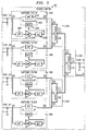
- FIG. 6 discloses a detailed schematic of switched filter 500 which comprises several sections. Recall that the purpose of the switched filter is to shut down the sub-low frequency band on all feeder lines with no upstream communication. This is best done within feeder switch 50, and more particularly by the addition of a switched filter circuit 500 for each subscriber. The operation of the switched filter circuit will be better understood when two modes of operation are identified: (i) downstream transmission only, (ii) downstream and upstream transmission.
- high pass filter 510 When transmission is in the downstream direction only, high pass filter 510 is basically the only functional circuit. This is accomplished by forward biasing diodes 582 and 584, while reverse biasing diodes 583 and 585. Accordingly, signals in the VHF frequency band enter port B, propagate through high pass filter 510, and continue toward the subscriber via port A. In this particular path, coupling capacitors 581, 586 are used to block DC current flow between the switched filter and the cables which are connected to ports A and B.
- High pass filter 510 is a fifth-order, Chebyshev filter whose cutoff frequency is 50 MHz. High pass filter 510 comprises components 511-517 which provide a relatively low impedance to signals at or above 50 MHz, but relatively high impedance otherwise.
- Forward biasing diodes 582 and 584 is accomplished when transistor 577 is turned on. Current flows from 12-volt source V B , through resistors 591 and 596, through diodes 582 and 584, through resistors 593 and 595, and hence through "on" transistor 577 to ground. Capacitors 592 and 594 provide an AC ground for the VHF signals and resistor 578 is used for connection to 24-volt source V A which keeps diodes 582 and 584 reverse biased when transistor 577 is in its off condition.
- PIN diodes 582-585 are silicon, RF switching diodes having low loss in the VHF frequency band. A suitable PIN diode is the BA582 switching diode which is commercially available from Siemens.
- transistor 577 When transmission proceeds in both the upstream and downstream directions, transistor 577 is turned off while transistor 572 is turned on. In this situation, PIN diodes 583 and 585 are forward-biased while diodes 582, 584 are reverse-biased. High pass filter 510 is therefore removed from the path between ports A and B, and replaced by direct connection 580 which not only passes the frequencies at or above 50 MHz, but also passes the frequencies in the sub-low frequency band used for upstream transmission. It is noted that the anode side of each of the PIN diodes is attached to the 12-volt source while the cathode side of these diodes is returned to the switched 24-volt source so that they can be suitably reverse-biased when it is desirable to turn then off.
- these diodes are turned on and off in pairs controlled by transistors 572 and 577 which respond to the same output signal from amplifier 560, but assume different logical states in response to the same input.
- a direct connection is made between ports A and B which bypasses the high pass filter 510. This condition is triggered when signals in the sub-low frequency band entering port A are detected by carrier detector 550.
- Coupling capacitor 521 connects low pass filter 520 to port A.
- Low pass filter 520 is a fifth-order, Chebyshev filter whose cutoff frequency is 37 MHz.
- Low pass filter 520 comprises components 522-529 which pass frequencies below the VHF frequency band, and in particular, frequencies in the frequency band 5-37 MHz.
- RF amplifier 530 comprises components 531-540.
- a suitable component for amplifier 540 is a commercially available IF amplifier such as the MC1350P.
- Capacitor 541 then couples the amplified signal from the RF amplifier 530 to carrier detector 550, and in particular to germanium diodes 551-552, configured as a voltage doubling rectifier, which demodulates the input signal through half-wave rectification.
- the rectified signal is then filtered by resistor 553 and capacitor 554 and presented to amplifier 560 - a conventional operational amplifier such as the LM324. Part of the rectified and amplified signal is fed back to RF amplifier 530 via resistors 557, 559 and capacitor 535 to provide negative feedback, and hence automatic gain control, for RF amplifier 530.
- the output of operational amplifier 560 is in its high (positive with respect to ground) state when an upstream signal is present, and in its low (ground) state otherwise.
- amplifier 560 When amplifier 560 is high, transistor 572 is saturated and transistor 572 is off which, as discussed earlier, causes a low impedance path (direct connection) to be connected between ports A and B. Such low impedance connections are sometimes known as "shunts.”
- Resistors 571 and 576 at the base to transistors 572, 577 respectively, are used to limit the maximum base current that can flow through these transistors.
- Components 573, 574 and 575 are selected for bias considerations and to eliminate unwanted RF signals.
- the predetermined control signal may be transmitted by the subscriber, the headend, or another selected location.
- the predetermined control signal need not reside in the sub-low frequency band, as presently contemplated, but may be at VHF at baseband.
- transmission in the upstream direction may occur in any frequency band(s).
Landscapes
- Engineering & Computer Science (AREA)
- Multimedia (AREA)
- Signal Processing (AREA)
- Two-Way Televisions, Distribution Of Moving Picture Or The Like (AREA)
Applications Claiming Priority (2)
| Application Number | Priority Date | Filing Date | Title |
|---|---|---|---|
| US81163491A | 1991-12-23 | 1991-12-23 | |
| US811634 | 1991-12-23 |
Publications (1)
| Publication Number | Publication Date |
|---|---|
| EP0549129A1 true EP0549129A1 (de) | 1993-06-30 |
Family
ID=25207106
Family Applications (1)
| Application Number | Title | Priority Date | Filing Date |
|---|---|---|---|
| EP92310671A Withdrawn EP0549129A1 (de) | 1991-12-23 | 1992-11-23 | Speiseschalter für ein bidirektionales Kabelfernsehsystem |
Country Status (3)
| Country | Link |
|---|---|
| EP (1) | EP0549129A1 (de) |
| JP (1) | JPH0686284A (de) |
| CA (1) | CA2079284A1 (de) |
Cited By (7)
| Publication number | Priority date | Publication date | Assignee | Title |
|---|---|---|---|---|
| NL9401664A (nl) * | 1994-10-10 | 1996-05-01 | Media Concept Licensing Ltd | Produktie- en distributiesysteem van televisieprogramma's en informatie. |
| DE19647944A1 (de) * | 1996-11-20 | 1998-05-28 | Alsthom Cge Alcatel | Aktiver Übergabepunkt eines Zugangsnetzes |
| WO1999030449A1 (en) * | 1997-12-05 | 1999-06-17 | Com21, Inc. | An apparatus for upstream signal selection |
| WO2001045412A1 (en) * | 1999-12-14 | 2001-06-21 | Kjell Arne Ljungdahl | Local network forming part of a cable tv system |
| WO2001062003A1 (en) * | 2000-02-16 | 2001-08-23 | Kjell Arne Ljungdahl | Cable tv system or other similar communication system |
| WO2003009596A1 (en) * | 2001-07-13 | 2003-01-30 | Protan Investments Limited | Arrangement for the reduction of noise transmitted from a local cable tv network |
| US6714598B2 (en) | 2002-04-29 | 2004-03-30 | Scientific-Atlanta, Inc. | Burst-mode combining of reverse path radio frequency signals |
Families Citing this family (2)
| Publication number | Priority date | Publication date | Assignee | Title |
|---|---|---|---|---|
| US6031432A (en) * | 1997-02-28 | 2000-02-29 | Schreuders; Ronald C. | Balancing apparatus for signal transmissions |
| KR20010069547A (ko) * | 2001-04-16 | 2001-07-25 | 이근웅 | 상향 잡음 감쇠기 |
Citations (2)
| Publication number | Priority date | Publication date | Assignee | Title |
|---|---|---|---|---|
| US3886454A (en) * | 1973-08-13 | 1975-05-27 | Rca Corp | Control apparatus for a two-way cable television system |
| US3924187A (en) * | 1974-05-14 | 1975-12-02 | Magnavox Co | Two-way cable television system with enhanced signal-to-noise ratio for upstream signals |
Family Cites Families (4)
| Publication number | Priority date | Publication date | Assignee | Title |
|---|---|---|---|---|
| JPS59161937A (ja) * | 1983-03-07 | 1984-09-12 | Miharu Tsushin Kk | 双方向catvシステムにおける集合雑音抑制方法 |
| JPS63309084A (ja) * | 1987-06-10 | 1988-12-16 | Sony Corp | 雑音低減回路 |
| CA1327238C (en) * | 1988-04-21 | 1994-02-22 | Michel Dufresne | Catv network with filters |
| JPH04296186A (ja) * | 1991-03-25 | 1992-10-20 | Nec Corp | 双方向catvシステム |
-
1992
- 1992-09-28 CA CA002079284A patent/CA2079284A1/en not_active Abandoned
- 1992-11-23 EP EP92310671A patent/EP0549129A1/de not_active Withdrawn
- 1992-12-22 JP JP35647092A patent/JPH0686284A/ja active Pending
Patent Citations (2)
| Publication number | Priority date | Publication date | Assignee | Title |
|---|---|---|---|---|
| US3886454A (en) * | 1973-08-13 | 1975-05-27 | Rca Corp | Control apparatus for a two-way cable television system |
| US3924187A (en) * | 1974-05-14 | 1975-12-02 | Magnavox Co | Two-way cable television system with enhanced signal-to-noise ratio for upstream signals |
Cited By (14)
| Publication number | Priority date | Publication date | Assignee | Title |
|---|---|---|---|---|
| NL9401664A (nl) * | 1994-10-10 | 1996-05-01 | Media Concept Licensing Ltd | Produktie- en distributiesysteem van televisieprogramma's en informatie. |
| DE19647944A1 (de) * | 1996-11-20 | 1998-05-28 | Alsthom Cge Alcatel | Aktiver Übergabepunkt eines Zugangsnetzes |
| AU729173B2 (en) * | 1996-11-20 | 2001-01-25 | Alcatel | Active demarcation point of an access network |
| US6320878B1 (en) | 1996-11-20 | 2001-11-20 | Alcatel | Active demarcation point of an access network |
| WO1999030449A1 (en) * | 1997-12-05 | 1999-06-17 | Com21, Inc. | An apparatus for upstream signal selection |
| US6137793A (en) * | 1997-12-05 | 2000-10-24 | Com21, Inc. | Reverse path multiplexer for use in high speed data transmissions |
| AU776113B2 (en) * | 1999-12-14 | 2004-08-26 | Proxilliant Systems Ab | Local network forming part of a cable TV system |
| WO2001045412A1 (en) * | 1999-12-14 | 2001-06-21 | Kjell Arne Ljungdahl | Local network forming part of a cable tv system |
| RU2259641C2 (ru) * | 1999-12-14 | 2005-08-27 | Протан Инвестментс Лимитед | Местная сеть, являющаяся частью системы кабельного телевидения |
| WO2001062003A1 (en) * | 2000-02-16 | 2001-08-23 | Kjell Arne Ljungdahl | Cable tv system or other similar communication system |
| RU2259021C2 (ru) * | 2000-02-16 | 2005-08-20 | Протан Инвестментс Лимитед | Система кабельного телевидения или аналогичная ей система связи |
| US7283479B2 (en) | 2000-02-16 | 2007-10-16 | Spacenet Proxilliant Systems Ab | Cable TV system or other similar communication system |
| WO2003009596A1 (en) * | 2001-07-13 | 2003-01-30 | Protan Investments Limited | Arrangement for the reduction of noise transmitted from a local cable tv network |
| US6714598B2 (en) | 2002-04-29 | 2004-03-30 | Scientific-Atlanta, Inc. | Burst-mode combining of reverse path radio frequency signals |
Also Published As
| Publication number | Publication date |
|---|---|
| JPH0686284A (ja) | 1994-03-25 |
| CA2079284A1 (en) | 1993-06-24 |
Similar Documents
| Publication | Publication Date | Title |
|---|---|---|
| US4077006A (en) | Bidirectional unicable switching system | |
| US5488413A (en) | CATV telephony system using subsplit band for both directions of transmission | |
| EP0488289B1 (de) | Videonetzwerksystem | |
| US5812665A (en) | Switched channel system | |
| US5485630A (en) | Audio/video distribution system | |
| US10136180B2 (en) | Intelligent device system and method for distribution of digital signals on a wideband signal distribution system | |
| US6161011A (en) | Hybrid fiber coax communications systems | |
| US5534912A (en) | Extended range video on demand distribution system | |
| EP0859514B1 (de) | Kabelfernsehsystem | |
| CA2251698C (en) | A method and system to transmit video/data signals from a device to a communications network connection card | |
| EP0965223B1 (de) | Verteilung von fernsehsignalen durch satelliten | |
| GB2256115A (en) | Switched cable television networks. | |
| WO1991008631A1 (en) | Method and apparatus for transmitting broadband amplitude modulated radio frequency signals over optical links | |
| CA2169684A1 (en) | Optical transmission system for cable television signals and video and telecommunications signals | |
| US20050034167A1 (en) | Wideband CATV tap device | |
| CA2234024C (en) | System to reduce gain variance and ingress in catv return transmissions | |
| EP0549129A1 (de) | Speiseschalter für ein bidirektionales Kabelfernsehsystem | |
| USRE31639E (en) | Bidirectional unicable switching system | |
| JP2001359068A (ja) | 2方向性通信装置用の信号インタフェース | |
| PL193682B1 (pl) | Sposób i układ rozprowadzania danych | |
| US12126388B2 (en) | Forward and reverse test point circuit with switchable termination for use in an RF amplifier | |
| WO2002104024A1 (en) | An intelligent device system and method for distribution of digital signals on a wideband signal distribution system | |
| KR100335526B1 (ko) | 신호 분배 회로 | |
| US7617517B2 (en) | Cable modem including filtering based on frequency band | |
| Large | Creating a network for interactivity |
Legal Events
| Date | Code | Title | Description |
|---|---|---|---|
| PUAI | Public reference made under article 153(3) epc to a published international application that has entered the european phase |
Free format text: ORIGINAL CODE: 0009012 |
|
| AK | Designated contracting states |
Kind code of ref document: A1 Designated state(s): FR GB |
|
| 17P | Request for examination filed |
Effective date: 19931203 |
|
| RAP3 | Party data changed (applicant data changed or rights of an application transferred) |
Owner name: AT&T CORP. |
|
| 17Q | First examination report despatched |
Effective date: 19960429 |
|
| 18W | Application withdrawn |
Withdrawal date: 19960524 |