EP0548868B1 - Method of refining of high purity steel - Google Patents

Method of refining of high purity steel Download PDF

Info

Publication number
EP0548868B1
EP0548868B1 EP92121682A EP92121682A EP0548868B1 EP 0548868 B1 EP0548868 B1 EP 0548868B1 EP 92121682 A EP92121682 A EP 92121682A EP 92121682 A EP92121682 A EP 92121682A EP 0548868 B1 EP0548868 B1 EP 0548868B1
Authority
EP
European Patent Office
Prior art keywords
molten steel
flux
ladle
cao
injecting
Prior art date
Legal status (The legal status is an assumption and is not a legal conclusion. Google has not performed a legal analysis and makes no representation as to the accuracy of the status listed.)
Expired - Lifetime
Application number
EP92121682A
Other languages
German (de)
French (fr)
Other versions
EP0548868A2 (en
EP0548868A3 (en
Inventor
Yoshiei c/o Tecnical Research Division Kato
Tadasu c/o Tecnical Research Division Kirihara
Seiji c/o Tecnical Research Division Taguchi
Tetsuya c/o Tecnical Research Division Fujii
Shigeru c/o Mizushima Works ofDivision Omiya
Masahito c/o Mizushima Works ofDivision Suito
Current Assignee (The listed assignees may be inaccurate. Google has not performed a legal analysis and makes no representation or warranty as to the accuracy of the list.)
JFE Steel Corp
Original Assignee
Kawasaki Steel Corp
Priority date (The priority date is an assumption and is not a legal conclusion. Google has not performed a legal analysis and makes no representation as to the accuracy of the date listed.)
Filing date
Publication date
Priority claimed from JP3340674A external-priority patent/JPH05171253A/en
Priority claimed from JP01906592A external-priority patent/JP3404760B2/en
Priority claimed from JP4031863A external-priority patent/JP3002593B2/en
Priority claimed from JP03945492A external-priority patent/JP3370349B2/en
Priority claimed from JP4094175A external-priority patent/JP3002599B2/en
Priority claimed from JP4094176A external-priority patent/JPH05287359A/en
Priority claimed from JP15345092A external-priority patent/JP3260417B2/en
Application filed by Kawasaki Steel Corp filed Critical Kawasaki Steel Corp
Publication of EP0548868A2 publication Critical patent/EP0548868A2/en
Publication of EP0548868A3 publication Critical patent/EP0548868A3/en
Publication of EP0548868B1 publication Critical patent/EP0548868B1/en
Application granted granted Critical
Anticipated expiration legal-status Critical
Expired - Lifetime legal-status Critical Current

Links

Images

Classifications

    • C—CHEMISTRY; METALLURGY
    • C21—METALLURGY OF IRON
    • C21C—PROCESSING OF PIG-IRON, e.g. REFINING, MANUFACTURE OF WROUGHT-IRON OR STEEL; TREATMENT IN MOLTEN STATE OF FERROUS ALLOYS
    • C21C7/00—Treating molten ferrous alloys, e.g. steel, not covered by groups C21C1/00 - C21C5/00
    • C21C7/10—Handling in a vacuum

Definitions

  • the present invention relates to secondary refining of molten steel, and particularly, to a method of effectively lowering impurities (sulphur, oxygen, nitrogen and carbon) in molten steel up to respective ultra-low ranges using a RH vacuum degassing unit.
  • a nozzle is provided on the inner wall of a vacuum vessel of a RH vacuum degassing unit in such a manner as to be inclined at 30-50° with respect to the horizontal direction, and the desulphurization is performed by injecting 1.7-4.0 kg/t of a flux to the steel bath surface within the vessel.
  • Japanese Patent Laid-open No. sho 58-9914 discloses a VOD process, wherein the desulphurization is performed by injecting a powder flux together with a carrier gas on the steel bath surface under the reduced pressure using a top-injecting lance.
  • this known technology does not teach how the desulphurizing reaction is exerted by the effect of the oxidizing slag (ladle slag), which inevitably flows out upon tapping the molten steel from the primary refining furnace such as a converter to a ladle. Therefore, it is doubtful whether or not the above technology may be applicable for the desulphurizing treatment in the RH vacuum degassing unit.
  • the melting of ultra-low carbon steel is commonly made by the steps of performing decarburization and dephosphorization in the converter, and of performing decarburization and deoxidation into a specified carbon concentration using a secondary refining unit such as an RH vacuum degassing unit or a DH unit.
  • a secondary refining unit such as an RH vacuum degassing unit or a DH unit.
  • a reducing agent in the case that a reducing agent is excessively charged, it reacts with the dissolved oxygen in the molten steel, which brings about the lack of the oxygen amount required for decarburization, or which causes the rephosphorization accompanied with the slag reducing action.
  • the melting of ultra-low sulphur steel has generally the following problem: namely, in the case of performing the desulphurization up to the ultra-low sulphur concentration region, it is necessary to increase the injected amount and the injecting time of the powder flux, and accordingly, the temperature drop due to the powder flux must be compensated by increasing the temperature of the molten steel.
  • the furnace tapping temperature is increased, the life of the refractories in the converter is deteriorated.
  • the powder is circulated between the vacuum vessel and the ladle together with the flow of the molten steel and is finally caught in the ladle.
  • the powder is commonly in the state of floating on the steel bath surface within the vacuum vessel and is not circulated. In the actual circumstances, the above conventional technologies has not solved this problem as yet.
  • JP-A-63-114 918 there is known a process for producing of flow sulphur clean steel which uses a powder blowing lens through which a lime-fluorite base desulphurization agent is blown onto the steel surface within a RH-OB unit.
  • JP-A-58-9914 a refining method for steel, said method making use of a flux powder which is sprayed with argon as a carrier gas through a top blowing lens into the steel.
  • the present invention intends to effectively realise the ultra-decarburization and the melting of high purity steel.
  • the prerefining process it is essential to apply dephosphorization and desulphurization to molten iron tapped from the blast furnace. Namely, by this prerefining process, the unit requirement of supplementary raw material such as CaO can be reduced on the whole melting process. Further, by this prerefining process, P 2 O 5 in the slag to be produced by converter blowing may be reduced, thereby eliminating the fear of causing rephosphorization into the molten steel during reduction of P 2 O 5 in the secondary refining process such as slag reforming and RH vacuum degassing treatment.
  • the carbon concentration at blowdown is specified to be 0.02 to 0.1%.
  • the carbon concentration is less than 0.02%, there arise the following inconveniences: namely, the concentration of iron oxide in slag becomes excessively higher, which exerts adverse effect on the converter refractories; the slag reforming becomes unstable: and, even when CaO or the like is injected from a top-injecting lance in the next RH vacuum degassing treatment, the slag-making between CaO and the slag component such as FeO is readily progressed thereby causing re-oxidation due to the slag, which obstructs the effective progress of the deoxidation.
  • the molten steel after decarburization is tapped in a ladle, and the slag reforming is performed therein.
  • the slag component it is essential to adjust the slag component to be (FeO + MnO) ⁇ 5% for preventing re-oxidation from the slag.
  • Fig. 2 shows a relationship between the total concentration of FeO and MnO and the oxygen concentration after RH vacuum degassing treatment.
  • the oxygen concentration after RH vacuum degassing treatment is rapidly increased. The reason for this is that the slag-making between FeO and MnO in the slag and the powder flux containing 50% or more of CaO is rapidly progressed, which obstructs the shielding effect by the flux for the slag-metal interface, thereby progressing re-oxidation.
  • the above molten steel is adjusted in specified concentrations of carbon and oxygen. Namely, oxygen or oxidizing gas containing oxygen is injected on the steel bath surface within a vacuum vessel of an RH vacuum degassing unit from a top-injecting lance disposed to the vacuum vessel according to the carbon concentration and the dissolved oxygen obtain in the above processes, and further, the temperature of the molten steel.
  • the injected oxygen in lack of the dissolved oxygen concentration, becomes the oxygen source in the steel and contributes to increase the decarburizing rate.
  • a part of oxygen burns CO gas produced by decarburization to convert it into CO 2 , and transmits the burning heat thereof to the molten steel.
  • powder containing hydrogen such as Ca(OH) 2 , Mg(OH) 2 , alum or the like is injected on the steel bath surface within the vacuum vessel from the above top-injecting lancer.
  • Ca(OH) 2 hydrogen atoms H in the steel produced by the reaction of Ca(OH) 2 ⁇ CaO + 2 H + O is converted to hydrogen molecules (2 H ⁇ H 2 ) in the vicinity of the steel bath surface.
  • the reaction interface area is simultaneously increased, which promotes the decarburizing reaction of C + O ⁇ CO. Accordingly, the stagnated decarburization generated in the ultra-low carbon range is eliminated, and therefore, the carbon concentration is rapidly lowered up to the limited value to be refined.
  • the molten steel is thus adjusted in a specified ultra-low carbon concentration, and subsequently deoxidized by the addition of a reducing agent such as Al in the vacuum vessel.
  • the molten steel is further adjusted in its composition.
  • the ultra-low carbon steel of the desired composition is obtained.
  • the slag composition is adjusted on tapping of the molten steel from the converter or in a ladle 10 in which the molten steel is tapped.
  • an RH vacuum degassing unit is mounted to the ladle 10, and oxygen or oxidizing gas containing oxygen is injected on the steel bath surface within a vacuum vessel 18 of the RH vacuum degassing unit from an top-injecting lance 20 disposed to the vacuum vessel 18 at least for a part of period for RH vacuum degassing treatment.
  • the oxidizing gas or the flux is injected from the top-injecting lance, the need of feeding a purge gas is eliminated when the injection is not performed, differently from the case of using an immersion lance. Thus, it is possible to suppress the temperature drop in the RH vacuum degassing treatment to a minimum.
  • the RH vacuum degassing treatment is performed as follows: Two immersion tubes 46 and 48 provided on the underside of a vacuum vessel 36 are immersed in a molten steel 32 within a ladle 30.
  • the molten steel 32 in the ladle 30 is lift-pumped within the vacuum vessel 36 while performing the exhaust through an exhaust port 34 provided on the upper portion of the vacuum vessel 36, and simultaneously argon gas is injected to the above lift-pumping immersion tube 46.
  • the degassing treatment is performed while the molten steel 32 is circulated between the ladle 30 and the vacuum vessel 36 by the above lift-pumping action.
  • the top-injecting lance 38 is descended within the vacuum vessel 36 and is made to face to the molten steel 32.
  • the flux 40 mainly containing CaO is injected on the molten steel surface together with a carrier gas such as argon at a gas flow rate of 10m/s or more.
  • the reason why the gas flow rate of the carrier gas is 10m/s or more is as follows; namely, for the flow rate less than 10m/s, the flux 40 is not effectively permeated into the molten steel 32; and for the flow rate more than 10m/s, even a fine powder flux (for example, under 325 mesh) is not sucked to the vacuum exhaust port 34 and is effectively permeated in the molten steel 32.
  • the effective desulphurization cannot be achieved merely by injecting the flux 40 in a specified amount. It is essential to inject the flux 40 in the specified amount according to the sectional area of the ladle. Namely, the flux 40 injected on the molten steel 32 and the ladle slag 42 having a high oxidizing potential must be perfectly shield the molten steel 32 from the ladle slag 42 for reducing the oxidizing potential at the reaction interface.
  • the flux amount may be reduced; and conversely, if being larger, the flux amount must be increased.
  • ⁇ / ⁇ 0.015A wherein ⁇ is an amount (kg) of powder mainly containing CaO, ⁇ is a density (kg/cm 3 ) of powder mainly containing CaO, A is a sectional area of a ladle at the position of the molten steel surface, and the value of 0.015 is a coefficient meaning the thickness of the flux.
  • the composition of the ladle slag having a high oxidizing potential it is preferable within the range of (%T ⁇ Fe) ⁇ 10.
  • the content of CaF 2 and/or Al 2 O 3 with respect to the total flux is specified at 5 to 40 wt%. The reason for this lies in improving the desulphurizing ratio due to the promotion of the slag-making for the main component, CaO.
  • the powder flux mainly containing CaO which is injected in the molten steel within the vacuum vessel of the RH vacuum degassing unit, reacts with sulphur in the molten steel and partially forms CaS.
  • the CaS thus formed flows in the ladle in the state being suspended in the molten steel, and subsequently, it is floated on the bath surface within the ladle, thus progressing the desulphurization. Further, the partial unreacted flux is also floated on the bath surface along the same path.
  • the CaS floated on the bath surface is contaminated in the slag deposited on the bath surface, At this time, when the oxidation degree of the slag is high, that is, (FeO + MnO) % is high, it may be considered that the CaS is decomposed again and [S] is returned into the molten steel, thereby obstructing the progress of the desulphurization. Accordingly, the adjustment of the slag composition is effective to improve the desulphurizing efficiency.
  • the flow rate of the powder flux injected on the molten steel within the vacuum vessel may be enlarged for increasing the desulphurizing efficiency.
  • the present inventors have examined the desulphurizing ratio in changing the injecting rate of the powder flux (CaO + 20%CaF 2 : 4kg/t) to the molten steel introduced in the vacuum vessel of the RH vacuum degassing unit. As a result, as shown in Fig. 10, it was revealed that the injecting rate is preferably within the range of 0.2kg/min or more per lt of the molten steel.
  • the reason why the injecting rate of the powder flux exerts the influence on the desulphurizing ratio is as follows: Namely, the flux suspended in the molten steel within the vacuum vessel is returned in the ladle and floated on the bath surface.
  • the floated flux is supposed to be deposited in a layer structure, and the growing rate of the deposited layer in the thickness direction is proportional to the flow rate of the injected powder flux. Also, the deposited layer reacts with the slag on the bath surface, and FeO and MnO in the slag is diffused in the flux, so that the flux is liable to be integrated with the slag.
  • the suitable range of the injection rate of the powder flux is considered to be changed according to the size of the equipment, for example, the sectional area of the ladle.
  • the powder flux may be injected at an injecting rate of 0.2 kg/min or more per lt of the molten steel.
  • the temperature of the molten steel is increased by adding aluminum or the reducing agent containing aluminum in the molten steel while injecting oxygen or oxidizing gas on the molten steel from a top-injecting lance 78.
  • the above treatment makes it possible to increase the temperature of the molten steel during the RH degassing treatment without increasing the furnace tapping temperature, and hence to enhance the desulphurizing efficiency.
  • the temperature drop caused by injection of a flux 80 from the top-injecting lancer 78 is able to be compensated.
  • the added amount of Al together with oxygen is specified as the following chemically correct mixture ratio: 2Al + 3/2O 2 ⁇ Al 2 O 3
  • the injected amount of CaO is about 1kg/t, preferably, more than 1kg/t.
  • the present inventors have examined the composition of the ladle slag at this time, and found the fact that, the desulphurization is rapidly progressed up to the ultra-low sulphur range under the condition that the component ratio among CaO, Al2O3 and SiO2 is specified by the following equation: W CaO /( W Al 2 O 3 + 2.5 W SiO 2 ) ⁇ 0.9 wherein W CaO is CaO wt% in the slag, is Al 2 O 3 wt% in the slag, and is SiO 2 wt% in the slag.
  • the top-injecting lance provided on the upper portion of the vacuum vessel is descended in the vacuum vessel, and the powder flux mainly containing CaO is injected on the molten steel surface together with the carrier gas such as argon gas, to be thus reacted with sulphur in the molten steel.
  • the carrier gas such as argon gas
  • the present invention was embodied according to the processes as shown in Fig. 1.
  • the molten iron was tapped in an amount of 300t from the blast furnace to the torpedo car. Subsequently, a flux was injected on the molten iron from an immersion lance for dephosphorization and desulphurization. At the same time, the slagging-off of the dephophorizing slag was made.
  • the dephosphorizing flux 25-35 kg/t of iron oxide, 8-15kg/t of quicklime and 1-2 kg/t of CaF 2 were used.
  • the desulphurizing flux 6-8 kg/t of (30%CaO + 70%CaCO 3 ) was used. In this molten iron prerefining process, phosphor content was lowered from 0.11-0.12% to 0.035-0.05%, and sulphur content was lowered from 0.02-0.03% to 0.005-0.009%.
  • a flux containing CaO as a main component and 40% of Al was added in an amount of 1.3-1.5kg per 1t of the molten steel for adjusting the total concentration of FeO and MnO in the slag deposited on the steel bath in the ladle to be 1.3-5.0%.At this time, the oxygen concentration in the molten steel was 100-550ppm, and the temperature of the molten steel was 1590-1610°C.
  • a water cooling lance vertically inserted from the top to the bottom of the vacuum vessel was fixed at such a position that the leading edge thereof was apart from the bath surface by 1.5-2.0m.
  • O 2 gas was injected on the steel bath surface at a flow rate of 30-50Nm 3 /min from the above lance, so that the O 2 concentration after injection was 500-600ppm and the temperature of the molten steel was 1595-1610 °C.
  • the composition of the molten steel thus treated was; C: 5-7ppm, Al: 0.03-0.04%, P: 0.024-0.030%, and S: 0.004-0.008%. Further, the temperature of the molten steel was 1570-1580°C.
  • the molten iron was blown in the converter.
  • the carbon content at the blow-down was 0.03-0.05% and the temperature of the molten steel was 1635-1650°C.
  • the molten steel in an amount of 280t was tapped to the ladle.
  • a reducing agent containing alumina as a main component and 40% of Al was added to the converter slag flown in the ladle, to thus adjust the total concentration of FeO and MnO in the slag to be 5% or less.
  • an immersion tube 12 of a RH vacuum degassing unit was inserted in a molten steel 14 of a ladle 10, and the molten steel 14 was introduced in a vacuum vessel 18 while performing the exhaust from an exhaust port 16.
  • Ar gas was injected in the molten steel from the immersion tube 12, and thereby the degassing treatment was made by the circulation of the molten steel using the lift-pumping action.
  • 120-280Nm 3 of O 2 gas was injected at a flow rate of 35Nm 3 /min from a top-injecting lancer 20 vertically inserted from the top to the bottom of the vacuum vessel.
  • Fig. 4 shows a relationship between the supplied amount of the powder flux 22 of CaO and the total oxygen amount in the steel after the RH treatment.
  • the flux in an amount of 3kg or more per 1t of the molten steel is required for stably melting a high purity steel containing the total oxygen in an amount of 15ppm or less.
  • Fig. 5 shows the change in the temperature of the molten steel during decarburization in the case that 3.3kg/t of the flux is top-injected after 180Nm 3 of O 2 gas is top-injected, or in the case that 2.5kg/t of the flux is top-injected without the top-injection of the O 2 gas.
  • the powder flux of CaO was used in this working example; however, the powder flux containing at least 50% of CaO sufficiently gives the desired effect, and therefore, it may contain MgO or the like, other than CaO.
  • the molten steel in an amount of 240-300t was tapped from the converter to the ladle. During tapping, fused slag in an amount of 2500-3500kg flowed in the ladle.
  • composition of the molten steel on tapping was; C: 0.04-0.06%, Si: 0.15-0.25%, Al: 0.03-0.04%, and S: 0.003-0.004.
  • the slag composition was; CaO: 40-50%, SiO 2 : 12-18%, T ⁇ Fe: 7-11%, and Al 2 O 3 : 15-20%.
  • the above molten steel was subjected to RH treatment.
  • the treatment time was 20 min. and the vacuum degree was 0.4-0.5 Torr.
  • the flow rate of a carrier gas in injecting the powder in the vessel was 3-6Nm 3 /min, and the top-blowing lance of single opening type or Laval type was used. Table 2 shows this working example and the comparative example.
  • the desulphurization up to the ultra-low sulphur region cannot be achieved irrespective of the amount of the flux.
  • the comparative example 3-4 comparable with the working example 3-3 that is, in the case that the composition of the synthetic flux does not satisfy the requirement of the present invention, the ultra-low sulphur steel cannot be obtained.
  • the comparative example 3-5 wherein the flux is added not by injecting, but by top-addition within the vessel through free-falling, the requirement of the present invention is not satisfied, thereby making impossible to obtain the the ultra-low sulphur steel.
  • the contents of P and S were adjusted to be 0.036-0.048% and 0.002-0.003%, respectively. Subsequently, the molten iron was blown in the top-and-bottom-blown converter, and the molten steel in an amount of about 260t was tapped in the ladle.
  • FeSi alloy, FeMn alloy and Al were added in the molten steel, to thus adjust the molten steel in the ladle as follows; C: 0.11-0.13%, Mn: 1.2-1.3%, Si: 0.35-0.38%, Al: 0.025-0.053%, S: 0.003-0.004%, and P: 0.021-0.025%.
  • the powder flux containing CaO as a main component and 40% of Al was added in an amount of 1.5kg per 1t of the molten steel, to thus adjust the total concentration of [%FeO] and [%MnO] to be 5% or less.
  • Fig. 11 shows the relationship between the above sulphurizing ratio and the used amount of the flux per 1t of the molten steel.
  • the sulphurizing ratio was calculated on the basis of the equation of(1 -[%S] f /[%S] i ⁇ 100 , wherein [%S] f is a sulphur concentration before the treatment, and [%S] i is a sulphur concentration after the treatment.
  • the high sulphurizing ratio was obtained.
  • the increased concentration of P in the molten steel was within the allowable range of 0.001-0.002%.
  • the molten steel in an amount of 270-300t was tapped from the converter to the ladle.
  • the composition of the molten steel was; C: 0.04-0.05wt%, Si: 0.25-0/35wt%, Mn: 0.8-1.0wt%, P: 0.007wt% or less, Al: 0.02-0.04wt% and S: 0.002-0.004wt%.
  • the powder slag flowed in the ladle was reformed by the addition of a reducing agent containing Al.
  • the composition of the reformed slag was; CaO: 40-50%, SiO 2 : 10-17%, Al 2 O 3 : 18-23%, and (FeO + MnO): 0.5-5.0%.
  • the amount of the reformed slag was 2500-3500kg.
  • the molten steel of the above composition was subjected to RH vacuum degassing treatment.
  • the treatment time was 20-25 min. and the vacuum degree was 0.4-1.0 Torr.
  • the injecting rate of the oxygen from the top-injecting lance 6 was 30-60Nm 3 /min.
  • a carrier gas of Ar gas was supplied at the injecting rate of 3-5Nm 3 /min.
  • the top-injecting lance was apart from the bath surface by 1.0-2.5m.
  • the molten steel in an amount of about 270t was tapped from the converter to the ladle.
  • CaO was charged in an amount of 300-500kg/ch. Then, directly after tapping, 0.7kg/t of Al powder was added on the ladle slag, to thus reduce FeO and MnO in the ladle slag. After that, CaO was charged in an amount of 300-1000kg/ch, thus performing the RH vacuum degassing treatment.
  • the composition of the molten steel was; C: 0.08-0.15wt%, Si: 0.10-0.20wt%, Mn: 0.8-1.2wt%, P: 0.015-0.020wt%, S: 0.003-0.005wt%, and Al: 0.03-0.05wt%.
  • Fig. 14 The results of the sulphurizing experiment made under the above condition are shown in Fig. 14.
  • the abscissa indicates the index calculated by the slag composition and is represented as: W CaO /(W Al 2 O 3 + 2.5W SiO 2 )
  • each plot marked as a white circle corresponds to the case of FeO + MnO ⁇ 5%
  • each plot of a black circle corresponds to the case of FeO + MnO > 5%.

Landscapes

  • Chemical & Material Sciences (AREA)
  • Engineering & Computer Science (AREA)
  • Materials Engineering (AREA)
  • Metallurgy (AREA)
  • Organic Chemistry (AREA)
  • Treatment Of Steel In Its Molten State (AREA)

Description

Background of the Invention Field of the Invention
The present invention relates to secondary refining of molten steel, and particularly, to a method of effectively lowering impurities (sulphur, oxygen, nitrogen and carbon) in molten steel up to respective ultra-low ranges using a RH vacuum degassing unit.
Description of the Prior Technology
In secondary refining of molten steel, there has been known a method of supplying a flux in a vacuum vessel of a RH vacuum degassing unit for refining under desulphurization, wherein the flux is freely fallen on the bath surface within the vacuum vessel. Accordingly, for improving the reaction rate, the flux in the form of fine powder must be used. This brings about a large disadvantage that the added flux is sucked to the exhaust system before reaching the bath surface of the molten steel. To cope with the disadvantage of using the fine powder flux, there has been proposed a method of using the massive flux; however, it is inconvenient in degrading the reaction efficiency.
Also, there has been proposed a method of promoting the reaction while circulating both the molten steel and the flux by injecting a desulphurizing flux into the molten steel directly under a riser using the so-called immersion lance in the RH vacuum degassing unit disclosed in "Material and Process"; Vol 1. 1, pp. 1189 (1988). This known technology, however, has disadvantages that the immersion lance is short in its service life and is difficult in its management, and further, it is difficult to accurately guide both the injected gas and the flux in the riser and hence to manage the operation.
Further, differently from the above, there has been known such a desulphurizing refining technology as disclosed in Japanese Patent Laid-open No. sho 63-114918. In this technology, a nozzle is provided on the inner wall of a vacuum vessel of a RH vacuum degassing unit in such a manner as to be inclined at 30-50° with respect to the horizontal direction, and the desulphurization is performed by injecting 1.7-4.0 kg/t of a flux to the steel bath surface within the vessel. This known technology, however, is disadvantageous in that, since the flux is charged in the direction inclined to the steel bath surface, the catching efficiency of the flux to the molten steel becomes poor and the effective desulphurization is obstructed by the influence of the oxidizing potential of the slag on the steel bath.
Also, there has been such a technology as disclosed in Japanese Patent Laid-open No. sho 53-92320, wherein molten steel is secondarily refined by injecting a powder flux on the steel bath within a RH vacuum vessel. However, this known technology is intended to lower the oxygen concentration in the molten steel, and does not refer to the composition of the slag in a ladle which is extremely important requirement in the desulphurizing treatment. Therefore, it is entirely obscure whether or not the above technology is effective to the desulphurizing treatment which is the subject of the present invention.
Further, Japanese Patent Laid-open No. sho 58-9914 discloses a VOD process, wherein the desulphurization is performed by injecting a powder flux together with a carrier gas on the steel bath surface under the reduced pressure using a top-injecting lance. However, this known technology does not teach how the desulphurizing reaction is exerted by the effect of the oxidizing slag (ladle slag), which inevitably flows out upon tapping the molten steel from the primary refining furnace such as a converter to a ladle. Therefore, it is doubtful whether or not the above technology may be applicable for the desulphurizing treatment in the RH vacuum degassing unit.
On the other hand, the melting of ultra-low carbon steel is commonly made by the steps of performing decarburization and dephosphorization in the converter, and of performing decarburization and deoxidation into a specified carbon concentration using a secondary refining unit such as an RH vacuum degassing unit or a DH unit. In the melting method of this type, it is important to rapidly perform the decarburization and deoxidation up to the low concentration range, which is also desirable for improving the quality of the steel and for preventing the surface defects due to non-metallic inclusions.
To meet the above demand, there has been proposed technologies of effectively performing deoxidation. For example, "Iron and Steel"; No. 11, Vol. 76, pp. 1932-1939 discloses a technology of preventing re-oxidation of the steel bath due to oxides (iron oxide or manganese oxide) in the converter slag floating on the steel bath in the ladle through reduction of the converter slag. However, in this technology, it is impossible to rapidly measuring the amount and the composition of the converter slag floating on the steel bath in the ladle, and accordingly, the reduction is made unstable. For example, in the case that a reducing agent is excessively charged, it reacts with the dissolved oxygen in the molten steel, which brings about the lack of the oxygen amount required for decarburization, or which causes the rephosphorization accompanied with the slag reducing action.
Further, it has been pointed out that the essential decarburization is occasionally stagnated, particularly, in the ultra-low carbon range (for example, as disclosed in "Material and Process"; No. 1, Vol. 1. 3, pp. 168 to 171).
As described above, in the conventional technologies, there is not considered how to control the composition of the primary refining slag (ladle slag) discharged from the converter, and the composition of the secondary refining slag produced in the ladle or in the vacuum vessel of the RH vacuum degassing unit, which makes impossible to perform the effective desulphurization and the deoxidation.
For example, the above conventional technologies disclosed in Japanese Patent Laid-open Nos. sho 53-92320 and sho 63-114918 have the ideas relating to the injection of the desulphurizing and deoxidizing flux; however, they does not refer to the composition of the slag in the ladle at all. On the other hand, in the technology proposed in Japanese Patent Laid-open No. sho 58-9914, there appears the description on such a slag composition. The description, however, is made not on the operation of the RH vacuum degassing unit, but on the VOD process in which the slag is strongly stirred together with the steel bath. Further, the proposal relates to the technology of adjusting the basicity of the slag, and thus is not applicable for the RH vacuum degassing treatment as it is.
Also, differently from the problems of the conventional technologies, the melting of ultra-low sulphur steel has generally the following problem: namely, in the case of performing the desulphurization up to the ultra-low sulphur concentration region, it is necessary to increase the injected amount and the injecting time of the powder flux, and accordingly, the temperature drop due to the powder flux must be compensated by increasing the temperature of the molten steel. However, if the furnace tapping temperature is increased, the life of the refractories in the converter is deteriorated. Needless to say, there has been examined a method of performing desulphurization while compensating the temperature in the RH vacuum degassing treatment; but it has been not established as yet.
Further, as the other problem, in the case that the desulphurization is performed by injecting a powder flux on the surface of the molten steel in the RH vacuum degassing unit, it is desirable that the powder is circulated between the vacuum vessel and the ladle together with the flow of the molten steel and is finally caught in the ladle. The powder, however, is commonly in the state of floating on the steel bath surface within the vacuum vessel and is not circulated. In the actual circumstances, the above conventional technologies has not solved this problem as yet.
From EP-A-351 762, there is known a process for producing high cleaness extra low carbon steel including supplying a deoxidisation agent to a slag in a laddle for adjusting the T·Fe (total iron) concentration in said slag at lower than or equal to 5%. Subsequently, a vacuum degassing process is performed with an oxygen lens to lower the carbon content in the steel lower than or equal to 0.006%.
Furthermore, from JP-A-63-114 918, there is known a process for producing of flow sulphur clean steel which uses a powder blowing lens through which a lime-fluorite base desulphurization agent is blown onto the steel surface within a RH-OB unit.
Furthermore, there is known from JP-A-58-9914 a refining method for steel, said method making use of a flux powder which is sprayed with argon as a carrier gas through a top blowing lens into the steel.
It is an object of the present invention to solve the above discussed disadvantages of the conventional technologies and to provide a technology of refining ultra-low sulphur and oxygen steels by effectively performing desulphurization and deoxidization without causing any contamination of the molten steel. In particular, the present invention intends to effectively realise the ultra-decarburization and the melting of high purity steel.
The above object is achieved by the subject matter of claim 1.
Preferred embodiments and further improvements of the invention are defined in the depending sub-claims.
Brief Description of the Drawings
  • Fig. 1 is a flow chart showing an embodiment of the present invention;
  • Fig. 2 is a graph showing a relationship between (FeO + MnO) and the total amount of oxygen in steel after RH treatment;
  • Fig. 3 is a typical view showing a RH treatment unit.
  • Fig. 4 is a graph showing a relationship between the flux amount and the total amount of oxygen in steel after RH treatment;
  • Fig. 5 is a graph showing the effect of oxidizing gas injection exerted on the temperature of molten steel;
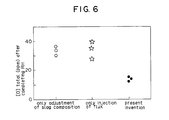
  • Fig. 6 is a graph showing a relationship between each treatment and the total amount of oxygen in steel after RH treatment;
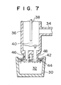
  • Fig. 7 is vertical sectional view of an RH degassing treatment unit;
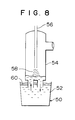
  • Fig. 8 is a typical view of an RH degassing treatment unit;
  • Fig. 9 is a graph showing a relationship between (FeO + MnO) and the desulphurizing ratio;
  • Fig. 10 is a graph showing a relationship between the injecting flow rate of a powder flux and the desulphurizing ratio;
  • Fig. 11 is a graph showing a relationship between the used amount of a flux and the desulphurizing ratio;
  • Fig. 12 is a sectional view showing the powder included state in the case of changing the bath depth;
  • Fig. 13 is a sectional view showing the powder included state in the case of changing the bath depth;
  • Fig. 14 is a view showing the desulphurizing ratio depending on the change in the slag composition; and
  • Fig. 15 is a view showing a relationship between the unit requirement of the flux and the desulphurizing ratio.
  • Description of the Preferred Embodiments
    Hereinafter, the present invention will be described in detail with reference to the flow chart of the embodiment as shown in Fig. 1.
    (1) Molten Iron Prerefining Process
    First, as the prerefining process, it is essential to apply dephosphorization and desulphurization to molten iron tapped from the blast furnace. Namely, by this prerefining process, the unit requirement of supplementary raw material such as CaO can be reduced on the whole melting process. Further, by this prerefining process, P2O5 in the slag to be produced by converter blowing may be reduced, thereby eliminating the fear of causing rephosphorization into the molten steel during reduction of P2O5 in the secondary refining process such as slag reforming and RH vacuum degassing treatment.
    (2) Converting Process
    In the converter, decarburization is mainly performed. Here, the carbon concentration at blowdown is specified to be 0.02 to 0.1%. When the carbon concentration is less than 0.02%, there arise the following inconveniences: namely, the concentration of iron oxide in slag becomes excessively higher, which exerts adverse effect on the converter refractories; the slag reforming becomes unstable: and, even when CaO or the like is injected from a top-injecting lance in the next RH vacuum degassing treatment, the slag-making between CaO and the slag component such as FeO is readily progressed thereby causing re-oxidation due to the slag, which obstructs the effective progress of the deoxidation. On the other hand, when the carbon concentration is more than 0.1%, the oxygen concentration under decarburization in the next RH vacuum degassing treatment is excessively lowered, which makes it impossible to achieve the rapid decarburization. In addition, in decarburization up to the low carbon level, there secondarily occurs dephosphorization in only a little degree.
    (3) Slag Reforming Process
    Subsequently, the molten steel after decarburization is tapped in a ladle, and the slag reforming is performed therein. Here, it is essential to adjust the slag component to be (FeO + MnO)≦ 5% for preventing re-oxidation from the slag.
    Fig. 2 shows a relationship between the total concentration of FeO and MnO and the oxygen concentration after RH vacuum degassing treatment. As is apparent from this figure, when the total concentration of FeO and MnO is more than 5%, the oxygen concentration after RH vacuum degassing treatment is rapidly increased. The reason for this is that the slag-making between FeO and MnO in the slag and the powder flux containing 50% or more of CaO is rapidly progressed, which obstructs the shielding effect by the flux for the slag-metal interface, thereby progressing re-oxidation.
    (4) RH Vacuum Degassing Treatment Process
    In the RH vacuum degassing treatment process, the above molten steel is adjusted in specified concentrations of carbon and oxygen. Namely, oxygen or oxidizing gas containing oxygen is injected on the steel bath surface within a vacuum vessel of an RH vacuum degassing unit from a top-injecting lance disposed to the vacuum vessel according to the carbon concentration and the dissolved oxygen obtain in the above processes, and further, the temperature of the molten steel. Here, in lack of the dissolved oxygen concentration, the injected oxygen becomes the oxygen source in the steel and contributes to increase the decarburizing rate. Also, a part of oxygen burns CO gas produced by decarburization to convert it into CO2, and transmits the burning heat thereof to the molten steel. By this injection of the oxidizing gas, it is possible to control the oxygen concentration and the treating temperature of the molten steel to be subjected to the RH vacuum degassing treatment, and hence to eliminate the severe management for the component and the temperature in the previous converting and slag reforming processes.
    Further, for decarburization up to the ultra-low carbon range, powder containing hydrogen such as Ca(OH)2, Mg(OH)2, alum or the like is injected on the steel bath surface within the vacuum vessel from the above top-injecting lancer. For example, in the case of injecting Ca(OH)2, hydrogen atoms H in the steel produced by the reaction of Ca(OH)2 ⇒ CaO + 2H  + O is converted to hydrogen molecules (2 H  ⇒ H2) in the vicinity of the steel bath surface. At this time, the reaction interface area is simultaneously increased, which promotes the decarburizing reaction of C + O ⇒ CO. Accordingly, the stagnated decarburization generated in the ultra-low carbon range is eliminated, and therefore, the carbon concentration is rapidly lowered up to the limited value to be refined.
    The molten steel is thus adjusted in a specified ultra-low carbon concentration, and subsequently deoxidized by the addition of a reducing agent such as Al in the vacuum vessel. The molten steel is further adjusted in its composition. Thus the ultra-low carbon steel of the desired composition is obtained.
    Next, there will be described another RH treatment process with reference to Fig. 3. First, the slag composition is adjusted on tapping of the molten steel from the converter or in a ladle 10 in which the molten steel is tapped. After that, an RH vacuum degassing unit is mounted to the ladle 10, and oxygen or oxidizing gas containing oxygen is injected on the steel bath surface within a vacuum vessel 18 of the RH vacuum degassing unit from an top-injecting lance 20 disposed to the vacuum vessel 18 at least for a part of period for RH vacuum degassing treatment. After completing the RH vacuum degassing treatment, Al is added, and subsequently, a powder flux 22 containing 50% or more of CaO is injected on the steel bath surface in an amount of 3kg per 1t of the molten steel from the above top-injecting lance 20.
    In the above treatment, by injecting the oxidizing gas on the steel bath surface within the vacuum vessel from the top-injecting lance, it is possible to increase the temperature of the molten steel, and hence to realize the injection of a large amount of the flux in the RH vacuum degassing treatment without remarkably increasing the temperature of the molten steel before being tapped to the ladle. This flux has a function to promote the floatation of non-metallic inclusions in the molten steel, thereby making it possible to refine the ultra-low carbon steel with high purity.
    The reason why the powder flux containing 50% or more of CaO is injected in an amount of 3kg or more per 1t of the molten steel lies in perfectly shielding the slag-metal interface by the flux. When the injected amount of the flux per 1t of the molten steel is less than 3kg, there arises such an inconvenience that the oxygen concentration after the RH vacuum degassing treatment is not lowered.
    Further, since the oxidizing gas or the flux is injected from the top-injecting lance, the need of feeding a purge gas is eliminated when the injection is not performed, differently from the case of using an immersion lance. Thus, it is possible to suppress the temperature drop in the RH vacuum degassing treatment to a minimum.
    With reference to Fig. 7, there will be described a technology of effectively performing desulphurization under low oxidizing potential by injecting the powder mainly containing CaO in a required amount according to the sectional area of the ladle on the steel bath surface within the RH vacuum vessel from the top-injecting lance.
    As shown in Fig. 7, the RH vacuum degassing treatment is performed as follows: Two immersion tubes 46 and 48 provided on the underside of a vacuum vessel 36 are immersed in a molten steel 32 within a ladle 30. The molten steel 32 in the ladle 30 is lift-pumped within the vacuum vessel 36 while performing the exhaust through an exhaust port 34 provided on the upper portion of the vacuum vessel 36, and simultaneously argon gas is injected to the above lift-pumping immersion tube 46. Thus, while the molten steel 32 is circulated between the ladle 30 and the vacuum vessel 36 by the above lift-pumping action, the degassing treatment is performed.
    According to the present invention, in the above RH treatment, the top-injecting lance 38 is descended within the vacuum vessel 36 and is made to face to the molten steel 32. Thus, from the leading edge of the top-injection lance 38, the flux 40 mainly containing CaO is injected on the molten steel surface together with a carrier gas such as argon at a gas flow rate of 10m/s or more. The reason why the gas flow rate of the carrier gas is 10m/s or more is as follows; namely, for the flow rate less than 10m/s, the flux 40 is not effectively permeated into the molten steel 32; and for the flow rate more than 10m/s, even a fine powder flux (for example, under 325 mesh) is not sucked to the vacuum exhaust port 34 and is effectively permeated in the molten steel 32.
    Incidentally, the effective desulphurization cannot be achieved merely by injecting the flux 40 in a specified amount. It is essential to inject the flux 40 in the specified amount according to the sectional area of the ladle. Namely, the flux 40 injected on the molten steel 32 and the ladle slag 42 having a high oxidizing potential must be perfectly shield the molten steel 32 from the ladle slag 42 for reducing the oxidizing potential at the reaction interface.
    Accordingly, even with the same amount of the molten steel, if the sectional area of the ladle is smaller, the flux amount may be reduced; and conversely, if being larger, the flux amount must be increased.
    The present inventors have earnestly studied, and found the fact that desulphurization is progressed up to the ultra-low sulphur level in the case that the following relationship is satisfied between the flux amount and the sectional area of the ladle. ω/ρ≧0.015A wherein ω is an amount (kg) of powder mainly containing CaO, ρ is a density (kg/cm3) of powder mainly containing CaO, A is a sectional area of a ladle at the position of the molten steel surface, and the value of 0.015 is a coefficient meaning the thickness of the flux.
    In addition, as the composition of the ladle slag having a high oxidizing potential, it is preferable within the range of (%T·Fe) ≦ 10. In the course of the present invention, it has been found the fact that, for the slag composition of (%T·Fe) > 10%, the flux does not achieve the perfect shielding effect between the slag and the metal. Here, the content of CaF2 and/or Al2O3 with respect to the total flux is specified at 5 to 40 wt%. The reason for this lies in improving the desulphurizing ratio due to the promotion of the slag-making for the main component, CaO.
    Next, there will be described the case of injecting the powder flux mainly containing CaO in the molten steel in the vacuum vessel of the RH vacuum degassing unit.
    The powder flux mainly containing CaO, which is injected in the molten steel within the vacuum vessel of the RH vacuum degassing unit, reacts with sulphur in the molten steel and partially forms CaS. The CaS thus formed flows in the ladle in the state being suspended in the molten steel, and subsequently, it is floated on the bath surface within the ladle, thus progressing the desulphurization. Further, the partial unreacted flux is also floated on the bath surface along the same path. The CaS floated on the bath surface is contaminated in the slag deposited on the bath surface, At this time, when the oxidation degree of the slag is high, that is, (FeO + MnO) % is high, it may be considered that the CaS is decomposed again and [S] is returned into the molten steel, thereby obstructing the progress of the desulphurization. Accordingly, the adjustment of the slag composition is effective to improve the desulphurizing efficiency.
    Also, in the above process, when the used amount of the powder flux is constant, the flow rate of the powder flux injected on the molten steel within the vacuum vessel may be enlarged for increasing the desulphurizing efficiency. The present inventors have examined the desulphurizing ratio in changing the injecting rate of the powder flux (CaO + 20%CaF2: 4kg/t) to the molten steel introduced in the vacuum vessel of the RH vacuum degassing unit. As a result, as shown in Fig. 10, it was revealed that the injecting rate is preferably within the range of 0.2kg/min or more per lt of the molten steel.
    The reason why the injecting rate of the powder flux exerts the influence on the desulphurizing ratio is as follows: Namely, the flux suspended in the molten steel within the vacuum vessel is returned in the ladle and floated on the bath surface. The floated flux is supposed to be deposited in a layer structure, and the growing rate of the deposited layer in the thickness direction is proportional to the flow rate of the injected powder flux. Also, the deposited layer reacts with the slag on the bath surface, and FeO and MnO in the slag is diffused in the flux, so that the flux is liable to be integrated with the slag. Accordingly, in the case that the growing rate of the flux deposited layer is large, the tendency to be integrated with the oxidizing slag containing FeO and MnO exceeds the growing rate of the flux deposited layer, so that the oxidation degree of the floated flux is increased and Gas in the flux is decomposed in the oxidizing environment. Thus, [S] is returned again in the molten steel, thereby reducing the desulphurizing ratio.
    On the other hand, in the case that the growing rate of the flux deposited layer is large enough to exceed the integrating tendency with the slag, FeO and MnO is restrictedly diffused and permeated to a part of the flux layer, as a result of which the flux composition in the vicinity of the interface in contact with the molten steel is not changed. Accordingly, CaS is not decomposed and the desulphurizing ratio is not reduced. In addition, the suitable range of the injection rate of the powder flux is considered to be changed according to the size of the equipment, for example, the sectional area of the ladle. However, as shown in Fig. 10, the substantial difference does not exist between the ladles of 100t and 250t. Consequently, in the operation on the commercial scale, the powder flux may be injected at an injecting rate of 0.2 kg/min or more per lt of the molten steel.
    Next, in the RH degassing treatment, with reference to Figs. 12 and 13, there will be described a process of adding aluminum and a reducing agent containing aluminum in the molten steel while injecting oxygen or oxidizing gas on the molten steel. First, in starting the RH degassing treatment, the temperature of the molten steel is increased by adding aluminum or the reducing agent containing aluminum in the molten steel while injecting oxygen or oxidizing gas on the molten steel from a top-injecting lance 78. The above treatment makes it possible to increase the temperature of the molten steel during the RH degassing treatment without increasing the furnace tapping temperature, and hence to enhance the desulphurizing efficiency. By the addition of Al in the molten steel together with oxygen, the temperature drop caused by injection of a flux 80 from the top-injecting lancer 78 is able to be compensated. In addition, the added amount of Al together with oxygen is specified as the following chemically correct mixture ratio: 2Al + 3/2O2 ⇒ Al2O3
    Thus, by increasing the temperature of the molten steel by means of the above oxygen injection and the addition of Al on the steel bath surface within the vacuum vessel, prior to injection of the powder flux such as CaO for the RH vacuum degassing treatment and desulphurization, the RH vacuum degassing treatment is not exerted by the influence of the previous process (converting), and the desulphurizing rate is promoted.
    Also, as another means, there is added a process of reducing the steel bath depth within the vacuum vessel during the above injection of CaO. As a result of a water model experiment made by the present inventors, in the case that the powder flux (average particle size: 0.5mm ) having a specific gravity smaller than water is injected on the steel bath surface, the smaller the bath depth is, the larger the ratio of the flux being circulated and contaminated in the molten steel within the ladle is.
    By the reduction in the bath depth, as shown in Fig. 13, CaO powder is also circulated in the ladle 70 without remaining in the vacuum vessel, so that the effective desulphurization may be expected as compared with the case, as shown in Fig. 12, that the bath depth is larger.
    Commonly, between CaO powder and [S] in the steel, a reaction of CaO + S ⇒ CaS +O. Accordingly, by making longer the time for which the injected CaO powder is circulated together with the molten steel to be thus contacted therewith, it is possible to increase the reaction efficiency. On the contrary, when the injected CaO powder remains on the steel bath surface 88 within the vacuum vessel 76, it seems reasonable that the desulphurizing efficiency is not increased due to the reduced reaction interface area.
    Thus, by combining the treatments of: increasing the temperature of the molten steel by means of the addition of oxygen or oxidizing gas and aluminum; reducing the steel bath depth within the vacuum vessel; and injecting CaO from the top-injecting lance, it is possible to remarkably improve the reaction efficiency of CaO. Accordingly, for achieving the sufficient desulphurizing performance, the injected amount of CaO is about 1kg/t, preferably, more than 1kg/t.
    In addition, the experiment was made under the condition of simultaneously satisfying the above treatments of increasing temperature of the molten steel, reducing the bath depth, and injecting CaO, which gave the result of the further excellent desulphurizing efficiency.
    Also, in the course of the research on the further desulphurizing method, the present inventors have found the fact that, even if FeO and MnO in the slag are controlled to be lowered, there occasionally occurs a large variation in the desulphurizing ratio.
    Thus, the present inventors have examined the composition of the ladle slag at this time, and found the fact that, the desulphurization is rapidly progressed up to the ultra-low sulphur range under the condition that the component ratio among CaO, Al2O3 and SiO2 is specified by the following equation: WCaO/( WAl2O3 + 2.5 WSiO2 ) ≧ 0.9 wherein WCaO is CaO wt% in the slag, is Al2O3 wt% in the slag, and is SiO2 wt% in the slag.
    Namely, under the condition that the composition of the ladle slag is out of the above equation, that is, under the undesirable condition, even if the flux injected on the steel bath surface within the vacuum vessel of the RH vacuum degassing unit has a high desulphurizing performance and CaS is generated by the reaction between CaO and [S] in the molten steel, when the flux particles are floated and contacted with the ladle slag, the produced CaS cannot be kept as it is and [S] is released in the molten steel, resulting in the reduced desulphurizing ratio.
    As described above, it is important to reform the composition of the ladle slag before performing the RH vacuum degassing treatment.
    Namely, during the RH vacuum degassing treatment, the top-injecting lance provided on the upper portion of the vacuum vessel is descended in the vacuum vessel, and the powder flux mainly containing CaO is injected on the molten steel surface together with the carrier gas such as argon gas, to be thus reacted with sulphur in the molten steel. Thus, a part of the injected powder flux becomes CaS, and simultaneously the powder flux is certainly floated on the slag layer deposited on the upper portion of the ladle, thereby promoting the desulphurizing reaction.
    The present invention will be more clearly understood with reference to the following examples:
    Working Example 1
    The present invention was embodied according to the processes as shown in Fig. 1.
    (1) Molten Iron Prerefining Process
    The molten iron was tapped in an amount of 300t from the blast furnace to the torpedo car. Subsequently, a flux was injected on the molten iron from an immersion lance for dephosphorization and desulphurization. At the same time, the slagging-off of the dephophorizing slag was made. In the above, as the dephosphorizing flux, 25-35 kg/t of iron oxide, 8-15kg/t of quicklime and 1-2 kg/t of CaF2 were used. Also, as the desulphurizing flux, 6-8 kg/t of (30%CaO + 70%CaCO3) was used. In this molten iron prerefining process, phosphor content was lowered from 0.11-0.12% to 0.035-0.05%, and sulphur content was lowered from 0.02-0.03% to 0.005-0.009%.
    (2) Converting Process
    Subsequently, 300t of the molten iron thus treated was blown in a top-and-bottom blown converter. The carbon content at the blowdown was 0.02-0.10% and the temperature of the molten steel was 1610-1630°C. In addition, the flow rate of the top-blowing O2 was 700Nm3/min, and the flow rate of the bottom-blowing inert gas was 20-30Nm3/min.
    (3) Slag Reforming Process
    During tapping the molten steel from the above converter to the ladle, a flux containing CaO as a main component and 40% of Al was added in an amount of 1.3-1.5kg per 1t of the molten steel for adjusting the total concentration of FeO and MnO in the slag deposited on the steel bath in the ladle to be 1.3-5.0%.At this time, the oxygen concentration in the molten steel was 100-550ppm, and the temperature of the molten steel was 1590-1610°C.
    (4) RH Vacuum Degassing Treatment Process
    At the time elapsing 2 min. since starting the RH vacuum degassing treatment, a water cooling lance vertically inserted from the top to the bottom of the vacuum vessel was fixed at such a position that the leading edge thereof was apart from the bath surface by 1.5-2.0m. O2 gas was injected on the steel bath surface at a flow rate of 30-50Nm3/min from the above lance, so that the O2 concentration after injection was 500-600ppm and the temperature of the molten steel was 1595-1610 °C.
    After that, from the above lance positioned to be apart from the bath surface by 1.5-1.8m, Ca(OH)2 powder was injected together with a carrier gas of Ar gas (2-3Nm3/min) at an injecting rate of 30-60kg/min. Thus, the concentrations of carbon and oxygen were adjusted to be 5-7ppm and 450-550ppm, respectively.
    Further, a reducing agent of Al was added in an amount of 1.2-1.4kg/t, and subsequently, the degassing treatment for the molten steel was made for 8-10 min. Thus, the RH degassing treatment was completed.
    The composition of the molten steel thus treated was; C: 5-7ppm, Al: 0.03-0.04%, P: 0.024-0.030%, and S: 0.004-0.008%. Further, the temperature of the molten steel was 1570-1580°C.
    Also, comparative examples were made by the treatments in which part of the above continuous processes was omitted, or by the treatments including the processes out of the present invention. The compositions of the molten steels thus obtained were examined. The results are shown in Table 1 together with those according to this working example.
    Figure 00310001
    Working Example 2
    The molten iron was blown in the converter. The carbon content at the blow-down was 0.03-0.05% and the temperature of the molten steel was 1635-1650°C. The molten steel in an amount of 280t was tapped to the ladle. A reducing agent containing alumina as a main component and 40% of Al was added to the converter slag flown in the ladle, to thus adjust the total concentration of FeO and MnO in the slag to be 5% or less.
    After that, as shown in Fig. 3, an immersion tube 12 of a RH vacuum degassing unit was inserted in a molten steel 14 of a ladle 10, and the molten steel 14 was introduced in a vacuum vessel 18 while performing the exhaust from an exhaust port 16. Subsequently, Ar gas was injected in the molten steel from the immersion tube 12, and thereby the degassing treatment was made by the circulation of the molten steel using the lift-pumping action. At the time elapsing 2 min. since starting the RH vacuum degassing treatment, 120-280Nm3 of O2 gas was injected at a flow rate of 35Nm3/min from a top-injecting lancer 20 vertically inserted from the top to the bottom of the vacuum vessel. For the time of 20 min. after starting the RH treatment, decarburization was made, and subsequently, deoxidation was made by the addition of Al to thus adjust the Al concentration in the molten steel to be 50×10-3%. After that, CaO powder 22 was supplied together with a carrier gas of Ar gas at an injection speed of 100-150kg/min from the top-injecting lance 20 further descended. For the time of 3-5 min. after injection of the CaO powder 22, the molten steel was circulated. Thus the RH treatment was completed.
    Fig. 4 shows a relationship between the supplied amount of the powder flux 22 of CaO and the total oxygen amount in the steel after the RH treatment. As is apparent from this figure, since the oxygen concentration is not lowered for the supplied amount of the CaO powder being less than 3kg per 1t of the molten steel, the flux in an amount of 3kg or more per 1t of the molten steel is required for stably melting a high purity steel containing the total oxygen in an amount of 15ppm or less.
    Further, by injecting O2 gas from the top-injecting lance during the RH treatment, a large amount of flux could be supplied without remarkably increasing the temperature of the molten steel before the RH treatment. Fig. 5 shows the change in the temperature of the molten steel during decarburization in the case that 3.3kg/t of the flux is top-injected after 180Nm3 of O2 gas is top-injected, or in the case that 2.5kg/t of the flux is top-injected without the top-injection of the O2 gas. As is apparent from this figure, by top-injecting O2 gas before the injection of the flux, the temperature of the molten steel in the vacuum vessel due to the secondary combustion generated during rimming treatment is increased, thereby making smaller the decreasing rate of the temperature during the treatment. When O2 gas was not injected under the condition that the temperature of the molten steel before the RH treatment is similar to the above, the temperature of the molten steel was lowered, and thus the amount of the flux was reduced.
    As compared with the case of adjusting the composition of the ladle slag and of injecting the flux, there were examined two comparative examples including only adjusting the composition of the ladle slag{(FeO + MnO) ≦ 5%), and only injecting the flux (3kg/t). In each of the comparative examples, the total oxygen amount in the steel after the RH treatment was obtained.The results are shown in Fig. 6. From this figure, it is revealed that the ultra-low carbon steel with high purity can be obtained only according to the combination of processes of the present invention.
    In addition, the powder flux of CaO was used in this working example; however, the powder flux containing at least 50% of CaO sufficiently gives the desired effect, and therefore, it may contain MgO or the like, other than CaO.
    Working Example 3
    The molten steel in an amount of 240-300t was tapped from the converter to the ladle. During tapping, fused slag in an amount of 2500-3500kg flowed in the ladle.
    The composition of the molten steel on tapping was; C: 0.04-0.06%, Si: 0.15-0.25%, Al: 0.03-0.04%, and S: 0.003-0.004.
    The slag composition was; CaO: 40-50%, SiO2: 12-18%, T·Fe: 7-11%, and Al2O3: 15-20%.
    The above molten steel was subjected to RH treatment. The treatment time was 20 min. and the vacuum degree was 0.4-0.5 Torr.
    As comparative charges, there were performed the methods of: (1) reducing the injected amount of the powder; and (2) adding the powder in the vacuum vessel.
    Also, the flow rate of a carrier gas in injecting the powder in the vessel was 3-6Nm3/min, and the top-blowing lance of single opening type or Laval type was used. Table 2 shows this working example and the comparative example.
    Hereinafter, there will be described the working examples and the comparative examples. As is apparent from Table 2, according to the present invention, wherein the flux containing CaO as a main component and 5-40% of CaF2, Al2O3, or a mixture of CaF2 and Al2O3 is injected to the molten steel circulating in the RH vacuum vessel so as to satisfy the relationship of ω/(ρ·A) ≧ 0.015, the sulphur concentration easily reaches the level by the ppm of one figure.
    On the contrary, as shown in the comparative examples 3-1 to 3-3 comparable with the working example 3-2, in the case of not satisfying the requirement of the present invention, that is, (ω/(ρ·A<0.015), the desulphurization up to the ultra-low sulphur region cannot be achieved irrespective of the amount of the flux. Also, in the comparative example 3-4 comparable with the working example 3-3, that is, in the case that the composition of the synthetic flux does not satisfy the requirement of the present invention, the ultra-low sulphur steel cannot be obtained. Further, in the comparative example 3-5 wherein the flux is added not by injecting, but by top-addition within the vessel through free-falling, the requirement of the present invention is not satisfied, thereby making impossible to obtain the the ultra-low sulphur steel.
    Figure 00380001
    Working Example 4
    In the molten iron tapped from the blast furnace, the contents of P and S were adjusted to be 0.036-0.048% and 0.002-0.003%, respectively. Subsequently, the molten iron was blown in the top-and-bottom-blown converter, and the molten steel in an amount of about 260t was tapped in the ladle. During tapping the molten steel in the ladle, FeSi alloy, FeMn alloy and Al were added in the molten steel, to thus adjust the molten steel in the ladle as follows; C: 0.11-0.13%, Mn: 1.2-1.3%, Si: 0.35-0.38%, Al: 0.025-0.053%, S: 0.003-0.004%, and P: 0.021-0.025%. Also, for lowering [%FeO] and [%MnO] in the slag on the steel bath surface within the ladle, the powder flux containing CaO as a main component and 40% of Al was added in an amount of 1.5kg per 1t of the molten steel, to thus adjust the total concentration of [%FeO] and [%MnO] to be 5% or less.
    Next, using an RH degassing unit as shown in Fig. 8, at the time elapsing 2 min. since starting the RH degassing treatment, a water cooling lance vertical inserted from the top to the bottom of the vacuum vessel was fixed at such a position that the leading edge thereof is apart from the bath surface by 1.5-2.0m. Then, CaO powder (average particle size: 68µm) containing 20% of CaF2 was injected together with a carrier gas of Ar gas at a flow rate of 0.2-0.5kg/min per 1t of the molten steel for 15-25 min. After that, alloys for adjusting the composition of the molten steel were added, and subsequently, the degassing treatment for the molten steel was made for 5-12 min., thus completing the RH degassing treatment.
    The above treatment was repeated by 10 charges, and the sulphurizing ratio was obtained on the basis of the change in [S] concentration after and before each treatment. Fig. 11 shows the relationship between the above sulphurizing ratio and the used amount of the flux per 1t of the molten steel. In addition, the sulphurizing ratio was calculated on the basis of the equation of(1 -[%S]f/[%S]i×100 , wherein [%S]f is a sulphur concentration before the treatment, and [%S]i is a sulphur concentration after the treatment. As shown in Fig. 11, according to the present invention, the high sulphurizing ratio was obtained. In addition, although the total concentration of FeO and MnO in the slag was lowered by the above treatment, the increased concentration of P in the molten steel was within the allowable range of 0.001-0.002%.
    Working Example 5
    The molten steel in an amount of 270-300t was tapped from the converter to the ladle. The composition of the molten steel was; C: 0.04-0.05wt%, Si: 0.25-0/35wt%, Mn: 0.8-1.0wt%, P: 0.007wt% or less, Al: 0.02-0.04wt% and S: 0.002-0.004wt%.
    The powder slag flowed in the ladle was reformed by the addition of a reducing agent containing Al. The composition of the reformed slag was; CaO: 40-50%, SiO2: 10-17%, Al2O3: 18-23%, and (FeO + MnO): 0.5-5.0%. The amount of the reformed slag was 2500-3500kg.
    After adjustment of the composition of the reformed slag in the ladle described above, the molten steel of the above composition was subjected to RH vacuum degassing treatment. The treatment time was 20-25 min. and the vacuum degree was 0.4-1.0 Torr. Also, the injecting rate of the oxygen from the top-injecting lance 6 was 30-60Nm3/min. In injection CaO powder, a carrier gas of Ar gas was supplied at the injecting rate of 3-5Nm3/min. In addition, the top-injecting lance was apart from the bath surface by 1.0-2.5m.
    The results of this working example and the comparative example are shown in Table 3. As is apparent from Table 3, in the working examples 5-1 to 5-11 in Table 3, the sulphur concentration after treatment easily reaches the level being less than 10ppm. On the other hand, as shown in the comparative example 5-2, when the top-injected amount of O2 is changed and the bath depth is changed by moving the ladle up and down, for the injected amount of the powder mainly containing CaO being less than 1kg/t, there is not generated the remarkably preferable sulphurizing effect. Also, as shown in the comparative examples 5-1 and 5-3, when the bath depth is made constant and O2 is not top-injected, for the injected amount of the powder containing CaO being 1kg/t or more, the sulphur concentration cannot reach the ultra-low level being less than 10ppm. This exhibits the predominance of the present invention.
    Figure 00430001
    Working Example 6
    The molten steel in an amount of about 270t was tapped from the converter to the ladle.
    For adjusting the slag composition during the tapping, CaO was charged in an amount of 300-500kg/ch. Then, directly after tapping, 0.7kg/t of Al powder was added on the ladle slag, to thus reduce FeO and MnO in the ladle slag. After that, CaO was charged in an amount of 300-1000kg/ch, thus performing the RH vacuum degassing treatment.
    The composition of the molten steel was; C: 0.08-0.15wt%, Si: 0.10-0.20wt%, Mn: 0.8-1.2wt%, P: 0.015-0.020wt%, S: 0.003-0.005wt%, and Al: 0.03-0.05wt%.
    In the RH vacuum degassing treatment, at the time elapsing 3 min. since starting the treatment, 2kg/t of the flux was injected together with Ar gas. At this time, the composition of the flux was; CaO: 80wt%, and CaF2: 20wt%. The RH vacuum degassing treatment was performed for 20 min.
    The results of the sulphurizing experiment made under the above condition are shown in Fig. 14. In this figure, the abscissa indicates the index calculated by the slag composition and is represented as: WCaO/(WAl2O3 + 2.5W SiO2 )
    Also, in this figure, each plot marked as a white circle corresponds to the case of FeO + MnO ≦ 5%, and each plot of a black circle corresponds to the case of FeO + MnO > 5%.
    As a result shown in Fig. 14, in the case of FeO + MnO≦ 5%, the desulphurizing ratio is low irrespective of the slag composition. Also, even in the case of FeO + MnO > 5%, if the equation of is not satisfied, the desulphurizing ratio is low, that is, the effective desulphurization does not performed.
    As described above, it becomes apparent to the desulphurizing method of the present invention enable the effective desulphurization.
    Next, the experiment was repeated, except for changing the unit requirement of the flux. The result is shown in Fig. 15.
    As is apparent from Fig. 15, for the unit requirement of the flux being 1kg/t or less, even if the slag composition is suitably adjusted, the desulphurizing ratio is low. The reason for this is that, since the desulphurization is mainly dependent on the injected flux, the unit requirement being 1kg/t or less seems to be simply small for effecting the desulphurization.

    Claims (9)

    1. A method of refining of a high purity steel comprising:
      (1) a prerefining process of suppressing the contents of P and S contained in molten iron tapped from a blast furnace to be 0.05wt% or less and 0.01wt% or less, respectively;
      (2) a process of decarburizing the molten iron after said prerefining process in a converter in such a manner that the carbon content is within the range of 0.02-0.1wt%;
      (3) a process of adding a reducing agent and a flux on the bath surface of a ladle containing a molten steel after said decarburizing process, thereby adjusting the composition of slag formed on the bath surface in such a manner that the total concentration of FeO and MnO becomes 5wt% or less; and
      (4) a process of injecting an oxidizing gas on the bath surface of the molten steel introduced from the ladle to a vacuum vessel of an RH vacuum degassing unit, thereby adjusting the oxygen concentration and the temperature of the molten steel; injecting at a rate of 30 to 60 Kg/min a powder containing hydrogen for adjusting the carbon concentration of the molten steel in a specified range; and adding a deoxidizing agent within the vacuum vessel for deoxidizing the molten steel.
    2. A method according to claim 1 wherein said process (4) is effected by
      mounting an RH vacuum degassing unit to the ladle of process (3) and injecting said oxidizing gas from a top-injecting lance for at least a part of period of the RH vacuum degassing treatment; and
      adding Al on the molten steel after the RH vacuum degassing treatment, and subsequently, injecting a powder flux containing 50wt% or more of CaO in an amount of 3kg per 1t of said molten steel on the bath surface of the molten steel from said top-injecting lance.
    3. A method according to claim 1 wherein
      a powder flux containing CaO as a main component and 5-40wt% of CaF2 and/or Al2O3 is vertically injected on the surface of the molten steel circulating within a vacuum vessel together with a carrier gas at a flow rate of 10m/sec or more from said top-injecting lance in the amount specified by the following equation: ω/ρ ≧ 0.015A wherein ω is the weight of the powder mainly containing CaO (Kg), ρ is the density (kg/m3) of the powder mainly containing CaO, A is the sectional area (m2) of the ladle at the position of the surface of the molten steel, and the value of 0.015 is a coefficient equivalent to the thickness of a flux layer.
    4. A method according to claim 1 wherein within the ladle the concentration of Al in the molten steel is adjusted to 0.02wt% or more.
    5. A method according to claim 3 wherein the injected amount of the flux powder is specified to be 0.2 kg/min per 1t of the molten steel.
    6. A method according to claim 1 wherein a gas and a desulphurizing agent is injected on the steel bath surface within said vacuum vessel of a RH vacuum degassing unit from a top-injecting lance provided to the vessel, thereby desulphurizing the molten steel and wherein Al or a reducing agent containing Al is added and said powder flux mainly containing CaO is injected from said top-injecting lance in an amount of at least 1 kg/t.
    7. A method according to claim 1 wherein the bath depth of said molten steel remaining within said vacuum vessel is reduced, thereby circulating said injected powder flux between the vacuum vessel and a ladle together with the molten steel.
    8. A method according to claim 1 wherein the position of said ladle is descended in order to reduce the bath depth of the molten steel remaining within said vacuum vessel, thereby circulating said injected powder flux between the vacuum vessel and the ladle together with the molten steel.
    9. A method according to claim 1 comprising:
      charging CaO in a ladle during or after tapping, thereby adjusting the composition of ladle slag before RH vacuum degassing treatment to be the value represented as the following equation; and
      injecting a powder flux mainly containing CaO on the molten steel within the vacuum vessel from said top-injecting lance in an amount of at least 1.0 kg/t, thereby performing RH vacuum degassing treatment: WCaO / (WAl2o3 + 2.5WSiO2 ) ≧ 9 wherein WCaO is the content of CaO in slag (wt%), WAl2O3 is the content of Al2O3 in slag (wt%), and WSiO2 is the content of SiO2 in slag (wt%).
    EP92121682A 1991-12-24 1992-12-21 Method of refining of high purity steel Expired - Lifetime EP0548868B1 (en)

    Applications Claiming Priority (14)

    Application Number Priority Date Filing Date Title
    JP340674/91 1991-12-24
    JP3340674A JPH05171253A (en) 1991-12-24 1991-12-24 Method of desulfurizing molten steel
    JP01906592A JP3404760B2 (en) 1992-02-04 1992-02-04 Desulfurization method of molten steel
    JP19065/92 1992-02-04
    JP31863/92 1992-02-19
    JP4031863A JP3002593B2 (en) 1992-02-19 1992-02-19 Melting method of ultra low carbon steel
    JP03945492A JP3370349B2 (en) 1992-02-26 1992-02-26 Melting method of high cleanness ultra low carbon steel
    JP39454/92 1992-02-26
    JP4094175A JP3002599B2 (en) 1992-04-14 1992-04-14 Melting method for ultra low carbon steel with high cleanliness
    JP94176/92 1992-04-14
    JP94175/92 1992-04-14
    JP4094176A JPH05287359A (en) 1992-04-14 1992-04-14 Method for desulfurizing molten steel using rh vacuum degassing apparatus
    JP15345092A JP3260417B2 (en) 1992-06-12 1992-06-12 Method for desulfurizing molten steel using RH vacuum degasser
    JP153450/92 1992-06-12

    Publications (3)

    Publication Number Publication Date
    EP0548868A2 EP0548868A2 (en) 1993-06-30
    EP0548868A3 EP0548868A3 (en) 1994-09-07
    EP0548868B1 true EP0548868B1 (en) 1998-09-16

    Family

    ID=27563854

    Family Applications (1)

    Application Number Title Priority Date Filing Date
    EP92121682A Expired - Lifetime EP0548868B1 (en) 1991-12-24 1992-12-21 Method of refining of high purity steel

    Country Status (7)

    Country Link
    US (1) US5304231A (en)
    EP (1) EP0548868B1 (en)
    KR (1) KR960009168B1 (en)
    CN (1) CN1061381C (en)
    BR (1) BR9205155A (en)
    CA (1) CA2086193C (en)
    DE (1) DE69227014T2 (en)

    Families Citing this family (32)

    * Cited by examiner, † Cited by third party
    Publication number Priority date Publication date Assignee Title
    US5472479A (en) * 1994-01-26 1995-12-05 Ltv Steel Company, Inc. Method of making ultra-low carbon and sulfur steel
    JP3531218B2 (en) * 1994-06-20 2004-05-24 大同特殊鋼株式会社 Method for producing low carbon chromium-containing steel
    DE69624783T2 (en) * 1995-08-01 2003-09-25 Nippon Steel Corp., Tokio/Tokyo METHOD FOR VACUUM-FINISHING STEEL MELT
    CN1066774C (en) * 1995-08-28 2001-06-06 新日本制铁株式会社 Process for vacuum refining of molten steel and apparatus therefor
    JP3668081B2 (en) * 1998-12-25 2005-07-06 株式会社神戸製鋼所 Method for refining molten aluminum alloy and flux for refining molten aluminum alloy
    GB2410503B (en) * 2000-06-05 2005-09-07 Sanyo Special Steel Co Ltd High-cleanliness steel and process for producing the same
    GB2381537B (en) * 2000-06-05 2005-09-14 Sanyo Special Steel Co Ltd High-cleanliness steel and process for producing the same
    GB2406580B (en) * 2000-06-05 2005-09-07 Sanyo Special Steel Co Ltd High-cleanliness steel and process for producing the same
    JP2001342512A (en) * 2000-06-05 2001-12-14 Sanyo Special Steel Co Ltd High cleanliness steel and manufacturing method thereof
    KR100887132B1 (en) * 2002-08-20 2009-03-04 주식회사 포스코 Transformation method
    EP1428894A1 (en) * 2002-12-13 2004-06-16 SMS Mevac GmbH A method of degassing molten steel
    JP5092245B2 (en) 2006-02-09 2012-12-05 Jfeスチール株式会社 Denitrification method for molten steel
    CN100436603C (en) * 2007-03-28 2008-11-26 北京科技大学 Process of deoxygenating, desulfurizing and controlling non-metal inclusion content in steel
    CN100532615C (en) * 2007-12-18 2009-08-26 本钢板材股份有限公司 A method for smelting wheel steel
    US8105415B2 (en) * 2008-08-04 2012-01-31 Nucor Corporation Low cost making of a low carbon, low sulfur, and low nitrogen steel using conventional steelmaking equipment
    UA104595C2 (en) * 2008-08-04 2014-02-25 Ньюкор Корпорейшн method for making a steel with low carbon low sulphur low nitrogen using conventional steelmaking Equipment
    KR101689633B1 (en) * 2008-08-04 2016-12-26 누코 코포레이션 Low cost making of a low carbon, low sulfur, and low nitrogen steel using conventional steelmaking equipment
    CN101736129B (en) * 2010-01-05 2011-08-24 武汉钢铁(集团)公司 Method for removing total oxygen in molten steel
    US8523977B2 (en) * 2011-01-14 2013-09-03 Nucor Corporation Method of desulfurizing steel
    CN104070144A (en) * 2014-07-10 2014-10-01 马钢(集团)控股有限公司 Method for reducing falling slag of ladle and feeding device using same
    JP6354472B2 (en) * 2014-09-05 2018-07-11 新日鐵住金株式会社 Desulfurization treatment method for molten steel
    JP6281708B2 (en) * 2015-03-26 2018-02-21 Jfeスチール株式会社 Desulfurization method for molten steel
    CN107287386A (en) * 2016-03-31 2017-10-24 鞍钢股份有限公司 Method for producing clean steel by RH
    CN106011381B (en) * 2016-07-22 2018-04-24 唐山正丰钢铁有限公司 A kind of molten steel extra furnace dephosphorization production technology
    CN108611465A (en) * 2016-12-13 2018-10-02 鞍钢股份有限公司 Molten steel refining method for improving RH decarburization rate
    CN108220532A (en) * 2016-12-13 2018-06-29 鞍钢股份有限公司 Secondary refining method for improving cleanliness of molten steel
    CN106995868B (en) * 2017-05-27 2018-11-27 马鞍山华盛冶金科技发展有限公司 A method of using agent for purifying molten steel refining liquid steel
    CN109270239A (en) * 2017-07-13 2019-01-25 鞍钢股份有限公司 Method for evaluating slag inclusion absorption capacity
    CN111194357A (en) 2017-08-24 2020-05-22 纽科尔公司 Improved manufacturing of mild steel
    CN110079724B (en) * 2019-06-12 2020-06-02 中天钢铁集团有限公司 Smelting method of ultralow-oxygen medium-low carbon steel
    DE102020209299A1 (en) 2020-07-23 2022-01-27 Sms Group Gmbh Method of manufacturing steel strip
    CN117965840B (en) * 2024-03-29 2024-06-04 江苏省沙钢钢铁研究院有限公司 Converter phosphorus controlled smelting method for low temperature steel and production method of high quality low temperature steel

    Family Cites Families (9)

    * Cited by examiner, † Cited by third party
    Publication number Priority date Publication date Assignee Title
    JPS5392320A (en) * 1977-01-25 1978-08-14 Nippon Steel Corp Slag making and refining method in vacuum degassing apparatus
    JPS589914A (en) * 1981-06-30 1983-01-20 Sumitomo Metal Ind Ltd Refining method for steel
    US4426224A (en) * 1981-12-25 1984-01-17 Sumitomo Kinzoku Kogyo Kabushiki Gaisha Lance for powder top-blow refining and process for decarburizing and refining steel by using the lance
    JPS63114918A (en) * 1986-10-31 1988-05-19 Sumitomo Metal Ind Ltd Production of flow sulfur clean steel
    JPH01301814A (en) * 1988-05-30 1989-12-06 Kawasaki Steel Corp Refining method of high-cleanliness steel
    JP2575827B2 (en) * 1988-07-18 1997-01-29 川崎製鉄株式会社 Manufacturing method of ultra low carbon steel for continuous casting with excellent cleanliness
    JPH0699737B2 (en) * 1989-02-01 1994-12-07 株式会社メタル・リサーチ・コーポレーション Method for producing clean steel
    US5221326A (en) * 1990-05-17 1993-06-22 Kawasaki Steel Corporation Method of producing ultra-low-carbon steel
    US5152831A (en) * 1991-06-27 1992-10-06 Kawasaki Steel Corporation Method of producing ultra-low-carbon steel

    Also Published As

    Publication number Publication date
    EP0548868A2 (en) 1993-06-30
    EP0548868A3 (en) 1994-09-07
    KR960009168B1 (en) 1996-07-16
    KR930013155A (en) 1993-07-21
    CA2086193A1 (en) 1993-06-25
    BR9205155A (en) 1993-06-29
    CA2086193C (en) 1998-02-24
    CN1074712A (en) 1993-07-28
    US5304231A (en) 1994-04-19
    DE69227014T2 (en) 1999-02-18
    DE69227014D1 (en) 1998-10-22
    CN1061381C (en) 2001-01-31

    Similar Documents

    Publication Publication Date Title
    US5304231A (en) Method of refining of high purity steel
    RU2433189C2 (en) Method for obtaining steel for steel pipes with excellent resistance in acid medium
    CN101553583B (en) Melting method of ultra-low sulfur, low nitrogen and high purity steel
    JP2012184501A (en) Method for desulfurizing molten steel
    JP2014148737A (en) Method for producing extra-low-sulfur low-nitrogen steel
    JP2776118B2 (en) Melting method for non-oriented electrical steel sheet
    JPH06240338A (en) Method for desulfurizing molten steel
    JP4534734B2 (en) Melting method of low carbon high manganese steel
    JP3172550B2 (en) Manufacturing method of high cleanliness steel
    JP3241910B2 (en) Manufacturing method of extremely low sulfur steel
    JPH0153329B2 (en)
    JPH0987732A (en) Method of refining molten steel
    JP2005344129A (en) Method for refining molten steel
    JPH05230516A (en) Melting method for extra-low-carbon steel
    JP3260417B2 (en) Method for desulfurizing molten steel using RH vacuum degasser
    JP2985720B2 (en) Vacuum refining method for ultra low carbon steel
    JPH11293329A (en) Method for producing ultra-low carbon Si-killed steel with excellent cleanliness
    JP3198250B2 (en) Vacuum refining method for molten steel containing chromium
    JPS6318645B2 (en)
    JPH1192819A (en) Vacuum refining method for high clean ultra low nitrogen steel
    JPH1030116A (en) Manufacturing method of high purity steel
    JPH0971810A (en) Refining method of ultra-clean ultra-low carbon steel
    JP3277763B2 (en) Refining method of ultra clean low carbon steel
    JP3404760B2 (en) Desulfurization method of molten steel
    JPH11217623A (en) Refining method of molten steel in reflux vacuum degasser

    Legal Events

    Date Code Title Description
    PUAI Public reference made under article 153(3) epc to a published international application that has entered the european phase

    Free format text: ORIGINAL CODE: 0009012

    AK Designated contracting states

    Kind code of ref document: A2

    Designated state(s): BE DE FR GB SE

    17P Request for examination filed

    Effective date: 19931227

    PUAL Search report despatched

    Free format text: ORIGINAL CODE: 0009013

    AK Designated contracting states

    Kind code of ref document: A3

    Designated state(s): BE DE FR GB SE

    17Q First examination report despatched

    Effective date: 19961115

    GRAG Despatch of communication of intention to grant

    Free format text: ORIGINAL CODE: EPIDOS AGRA

    GRAG Despatch of communication of intention to grant

    Free format text: ORIGINAL CODE: EPIDOS AGRA

    GRAH Despatch of communication of intention to grant a patent

    Free format text: ORIGINAL CODE: EPIDOS IGRA

    GRAH Despatch of communication of intention to grant a patent

    Free format text: ORIGINAL CODE: EPIDOS IGRA

    GRAA (expected) grant

    Free format text: ORIGINAL CODE: 0009210

    AK Designated contracting states

    Kind code of ref document: B1

    Designated state(s): BE DE FR GB SE

    REF Corresponds to:

    Ref document number: 69227014

    Country of ref document: DE

    Date of ref document: 19981022

    ET Fr: translation filed
    PLBE No opposition filed within time limit

    Free format text: ORIGINAL CODE: 0009261

    STAA Information on the status of an ep patent application or granted ep patent

    Free format text: STATUS: NO OPPOSITION FILED WITHIN TIME LIMIT

    26N No opposition filed
    REG Reference to a national code

    Ref country code: GB

    Ref legal event code: IF02

    PGFP Annual fee paid to national office [announced via postgrant information from national office to epo]

    Ref country code: GB

    Payment date: 20101215

    Year of fee payment: 19

    PGFP Annual fee paid to national office [announced via postgrant information from national office to epo]

    Ref country code: DE

    Payment date: 20101215

    Year of fee payment: 19

    PGFP Annual fee paid to national office [announced via postgrant information from national office to epo]

    Ref country code: SE

    Payment date: 20111213

    Year of fee payment: 20

    Ref country code: FR

    Payment date: 20111219

    Year of fee payment: 20

    PGFP Annual fee paid to national office [announced via postgrant information from national office to epo]

    Ref country code: BE

    Payment date: 20111229

    Year of fee payment: 20

    REG Reference to a national code

    Ref country code: DE

    Ref legal event code: R071

    Ref document number: 69227014

    Country of ref document: DE

    BE20 Be: patent expired

    Owner name: *KAWASAKI STEEL CORP.

    Effective date: 20121221

    REG Reference to a national code

    Ref country code: GB

    Ref legal event code: PE20

    Expiry date: 20121220

    REG Reference to a national code

    Ref country code: SE

    Ref legal event code: EUG

    PG25 Lapsed in a contracting state [announced via postgrant information from national office to epo]

    Ref country code: GB

    Free format text: LAPSE BECAUSE OF EXPIRATION OF PROTECTION

    Effective date: 20121220