EP0548838B1 - Tamper evident container closure - Google Patents
Tamper evident container closure Download PDFInfo
- Publication number
- EP0548838B1 EP0548838B1 EP92121583A EP92121583A EP0548838B1 EP 0548838 B1 EP0548838 B1 EP 0548838B1 EP 92121583 A EP92121583 A EP 92121583A EP 92121583 A EP92121583 A EP 92121583A EP 0548838 B1 EP0548838 B1 EP 0548838B1
- Authority
- EP
- European Patent Office
- Prior art keywords
- container
- seal member
- cover
- seal
- closure
- Prior art date
- Legal status (The legal status is an assumption and is not a legal conclusion. Google has not performed a legal analysis and makes no representation as to the accuracy of the status listed.)
- Expired - Lifetime
Links
Images

Classifications
-
- B—PERFORMING OPERATIONS; TRANSPORTING
- B65—CONVEYING; PACKING; STORING; HANDLING THIN OR FILAMENTARY MATERIAL
- B65D—CONTAINERS FOR STORAGE OR TRANSPORT OF ARTICLES OR MATERIALS, e.g. BAGS, BARRELS, BOTTLES, BOXES, CANS, CARTONS, CRATES, DRUMS, JARS, TANKS, HOPPERS, FORWARDING CONTAINERS; ACCESSORIES, CLOSURES, OR FITTINGS THEREFOR; PACKAGING ELEMENTS; PACKAGES
- B65D79/00—Kinds or details of packages, not otherwise provided for
- B65D79/005—Packages having deformable parts for indicating or neutralizing internal pressure-variations by other means than venting
- B65D79/0087—Packages having deformable parts for indicating or neutralizing internal pressure-variations by other means than venting the deformable part being located in a closure, e.g. in caps or lids
Definitions
- This invention relates to tamper evident containers, and more particularly to closures having visible seals which reveal whether tampering or leakage has occurred, without the necessity of removing the closure to inspect the seal.
- Containers such as jars with screw-on caps have been provided with various means for indicating tampering.
- U.S. patent No. 4,778,069 discloses and claims a container having a tab extending from an inner seal through a slot in the container cover. Damage to the tab is indicative of tampering.
- U.S. Patent No. 4,553,678 has a film or foil seal which is visible through a transparent screw cap.
- U.S. patent No. 4,674,642 relates to a closure for a container having contents under vacuum.
- An inner liner has a projection which extends through an aperture in the container cap when vacuum is lost.
- U.S. Patent No. 4,122,964 discloses a closure for a container comprising a cover in form of a screw band or ring with a central aperture, to be screwed onto the mouth of the container, and a flexible lid between the the screw band and the container which is visible through the opening and adapted to be drawn partially inwards, when the pressure within the container is less than the pressure external to the container, in order to provide a visual indication of the existence of a hermetical seal.
- EP-A 0 269 920 discloses a composite closure comprising a molded plastic ring and a separated disk-like cover.
- the cover includes a gasket providing both top and side sealing for preventing loss of vacuum during retorting or other package handling.
- This cover is made of tin or rigid plastic and may comprise a button as secondary tamper indication.
- the main tamper indication is effected by a tamper indication band on the plastic ring.
- the sealing is effected by use of a gasket included within the disk-like cover.
- the aperture not be open when the cover is replaced. While this may be accomodated by retucking the seal it is desirable to use a closure which is more convenient for the consumer.
- an indication for tampering and/or loss of air tightness as well as a permanent closure of the aperture is achieved by affixing the seal member to the cover and sealing it to the rim, wherein the seal to the rim must be sufficiently strong to retain a hermetic seal but sufficiently weak to fail by shear when opening.
- the tamper evident container closure of the invention includes a seal member which is held in a concave or convex condition by a difference between the ambient pressure and the pressure of gas within the container.
- the seal member is visible through an opening in a top panel of the closure.
- a convex condition also provides a tactile indication of security. Pressing upon the seal member with a finger offers assurance of pressure, indicating that the seal has not been broached.
- the closure of the invention provides external evidence that a container, such as a jar or bottle with a screw-on cap, has been subjected to tampering or leakage without resorting to complex devices which are costly to manufacture and which are, in some cases, unreliable. There will be fewer false positive signals of tampering than will result from some of the prior art expedients, and fewer false negative signals than there would be with other prior art devices.
- the condition of a seal member reveals whether the container has been tampered with or otherwise opened.
- the configuration of the seal member changes from a convex or concave condition which denotes container integrity, to another condition, signaling that the container has been opened.
- the invention is discussed with reference to closure for a jar with a screw-on cover, but the invention is applicable to covers secured to containers by other means than mating screw threads, and to closures for other types of containers.
- the seal member which is sealingly secured to a lip of the container and affixed to a container cap or lid as well reveals whether the container has been opened.
- opened refers to either complete or partial removal of or leakage past the seal member, which could expose the container contents to unintentional contamination or tampering.
- the seal member is visible through an aperture in the container cover, such as a circular central hole in a flat top panel of the cover. Enough of the periphery of such an apertured panel is retained to provide pressure for sealing the seal member to the seal surface of the container.
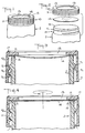
- FIGS. 1-10 show tamper evident container closures as applied to a screw-on cap of a wide mouth jar, although the invention can be employed in other types of closures, such as caps for bottles, etc.
- the jar generally designated by the reference character J in the several drawing figures, is hatched to indicate plastic material, but it could be a glass, ceramic or metal container.
- the jar J has an open mouth portion M provided with an integral outwardly projecting helical thread Tl for engagement with an inwardly projecting helical thread T2 of a cover 10 for the jar J as seen in Figs. 3 and 4 when the cover 10 is screwed on to close the mouth of the jar J.
- the cover or cap 10 which may be of plastic material, has the usual annular lip 11 which carries the thread T2, which lip can have multiplicity of external vertical extending grooves to allow manual gripping without slipping of the hand when opening or closing the container.
- the cover 10 instead of the conventional continous disc-shaped top panel, has only an annular peripheral portion 12, surrounding an opening 13 which occupies most of what would usually be the central area of a top panel of a cover.
- the annular peripheral portion 12 of the cover is sufficiently wide to provide pressure for sealing a seal member 14 to the rim 15 of the jar mouth M.
- the seal member 14 which is preferably a die cut disc of flexible foil laminated plastic material and/or coated paper, is fitted in place within the cover 10 and applied to the container by use of radio frequency induction heating or some other conventional technique.
- the seal member is affixed to the rim 15 of the container.
- the contents of the jar J can be filled by a conventional process such as hot filling, nitrogen injection, under- or over-saturation with soluble gas, flushing of a head space above the contents with a soluble gas, or by any other known technique which will result in a head space pressure beneath the seal member 14 that differs from atmospheric pressure.
- the pressure in the head space within the jar J is lower than atmospheric, and the seal member 14 is accordingly deformed into the concave conformation illustrated. This contraction of the seal member 14 is readily apparent to one inspecting the seal member 14 through the opening 13 of the cover 10.
- the cover 10 may also have a peripheral flange 17 for vertical stacking of containers.
- Fig. 3 shows the jar J with its sealing member 14 in a concave disposition, indicating that no tampering or leakage has allowed outside air to enter the jar J.
- an outwardly distended, convex seal 24 could indicate an overpressure in the jar J to signal that no leakage or tampering has taken place as in Fig. 6.
- Fig. 4 shows ambient air entering as illustrated by the direction of the arrows. If the contents were filled under an over-pressure, the pressurized gas would escape to the outside. In either case, the seal member 14 will respond by taking on the unstressed flat conformation shown in Fig. 4.
- FIG. 5 A modified version of the closure according to the invention is shown in Figs. 5 and 6.
- the seal member 24 is sealingly secured, to the rim 25 of the jar J.
- the seal 24 is shown as having a convex curvature in its undisturbed state.
- Fig. 6 shows the jar J as it would be received after filling.
- the closure of Fig. 5 and 6 has a central opening 23 like the opening 13 of the embodiment of Figs. 1 - 4, but the opening 23 can be smaller in diameter than the opening 13. The opening 23 permits inspection of the condition of the seal member 24 without removal of the cover 20.
- the invention in either form, allows printing on the seal member, whether it be a member 14, or 24, avoiding the need to put printed content identification or other information on the cover 10 or 20,
Abstract
Description
Claims (13)
- A tamper evident closure for a container (J) of the type in which a cover (20) is secured to a mouth of the container (J), comprising a flexible seal member (24) between the container (J) and the cover and visible through an opening in the cover (20), which seal member (24) is adapted to be curved away from a flat condition by a difference between pressures existing inside and outside the container (J) so that the integrity of the container (J) is detectable without removal of the container cover (20), characterized in that the seal member (24) is affixed to the cover (20) and sealed to a rim (25) of the container (J) and in that the seal between the seal member (24) and said rim (25) is adapted to fail by shearing when opening while the seal member (24) remains affixed to said cover (20).
- The closure of claim 1, wherein there are indicia on the seal member (24) which indicia are visible without removal of the container cover (20).
- The closure of claim 1, wherein the deformed seal member (24) provides tactile evidence of a sealed container (J).
- The closure of claim 1, wherein the deformation of the seal member (24) accomodates internal pressure greater than atmospheric pressure.
- A method of providing a container (J) with a seal for showing evidence of tampering or leakage of the container (J), comprising: providing a flexible seal member (24) between the container (J) and a cover (20) for the container (J), providing a pressure within the container (J) which differs from atmospheric pressure, whereby the seal member (24) is deformed from a flat condition by the pressure difference, and providing an opening in the cover (20) through which the condition of the seal member (24) is visible; characterized in that the method further comprises:providing a seal member (24) which is affixed to the cover (20) and sealed to the rim (25) of the container (J), wherein the seal between the seal member (24) and said rim (25) fails by shearing when opening while the seal member (24) remains affixed to said cover (20).
- The method of claim 4, wherein there are indicia on the seal member (24) which indicia are visible without removal of the container cover (20).
- The method of claim 5, wherein the deformed seal member (24) provides tactile evidence of a sealed container (J).
- The method of claim 5, wherein the deformation of the seal member (24) accomodates internal pressure greater than atmospheric.
- The method of claim 8, wherein said pressure is provided in said container (J) by over-saturation with a soluble gas.
- A tamper resistant food package, comprising;a) a container (J) including a mouth;b) a cover (20) for the container (J), said cover (20) adapted to cooperatively engage the mouth of the container (J);c) a tamper evident closure comprising a flexible seal member (24) between the container (J) and the cover (20) and visible through an opening in the cover (20), which seal member (24) is curved away from a flat condition by a pressure greater than atmospheric pressure existing inside the container (J) so that the integrity of the container (J) is detectable without removal of the container cover (20), andd) a foodstuff inside said container (J) characterized in that the seal member (24) is affixed to the cover (20) and sealed to a rim (25) of the container (J) and in that the seal between the seal member (24) and said rim (25) is adapted to fail by shearing when opening while the seal member (24) remains affixed to said cover (20).
- The food package of claim 10, further comprising indicia on the seal member (24) which are visible without removal of the container cover (20).
- The food package of claim 10, wherein said foodstuff has been over-saturated with a soluble gas.
- The food package of claim 10, wherein the deformed seal member (24) provides tactile evidence of a sealed container (J).
Applications Claiming Priority (2)
| Application Number | Priority Date | Filing Date | Title |
|---|---|---|---|
| US81273791A | 1991-12-23 | 1991-12-23 | |
| US812737 | 1997-03-05 |
Publications (3)
| Publication Number | Publication Date |
|---|---|
| EP0548838A2 EP0548838A2 (en) | 1993-06-30 |
| EP0548838A3 EP0548838A3 (en) | 1993-09-08 |
| EP0548838B1 true EP0548838B1 (en) | 1998-07-22 |
Family
ID=25210477
Family Applications (1)
| Application Number | Title | Priority Date | Filing Date |
|---|---|---|---|
| EP92121583A Expired - Lifetime EP0548838B1 (en) | 1991-12-23 | 1992-12-18 | Tamper evident container closure |
Country Status (7)
| Country | Link |
|---|---|
| EP (1) | EP0548838B1 (en) |
| AT (1) | ATE168649T1 (en) |
| CA (1) | CA2084389C (en) |
| DE (1) | DE69226341T2 (en) |
| DK (1) | DK0548838T3 (en) |
| ES (1) | ES2118781T3 (en) |
| GR (1) | GR3027783T3 (en) |
Families Citing this family (2)
| Publication number | Priority date | Publication date | Assignee | Title |
|---|---|---|---|---|
| GB2317882A (en) * | 1996-10-04 | 1998-04-08 | Chown Peter A C | A container for a pressurised food or drink product |
| DE10022177B4 (en) * | 1999-12-27 | 2004-02-12 | Uwe Friebe | Device for signaling the internal condition of a container |
Family Cites Families (8)
| Publication number | Priority date | Publication date | Assignee | Title |
|---|---|---|---|---|
| US4122964A (en) * | 1976-07-02 | 1978-10-31 | Morris Neal R | Reusable closures for hermetically sealing containers |
| GB2130565A (en) * | 1982-09-29 | 1984-06-06 | Patent Dev International Ltd | Container closures |
| FR2572708B1 (en) * | 1984-11-02 | 1990-02-09 | Jujo Paper Co Ltd | PAPER CONTAINER FOR LIQUIDS, AND METHOD AND APPARATUS FOR FILLING AND SEALING THE CONTAINER |
| US4721219A (en) * | 1986-11-17 | 1988-01-26 | Owens-Illinois Closure Inc. | Composite, vacuum indicating closure |
| EP0269920A1 (en) * | 1986-11-20 | 1988-06-08 | Anchor Hocking Corporation | An improved composite closure cap and package |
| US4852753A (en) * | 1987-05-11 | 1989-08-01 | Anchor Hocking Corporation | Closure cap and thin walled container |
| US5057365A (en) * | 1989-07-12 | 1991-10-15 | 501 Tri-Seal International, Inc. | Cap liner and process for using cap liner to seal containers |
| DE4020371C1 (en) * | 1990-06-27 | 1991-12-19 | Kroma, Herrmann Und Wolf Nachfolger Norbert Herrmann, 6246 Glashuetten, De | Sealing of glass and plastics containers - involves use of metallic layer and induction ring |
-
1992
- 1992-12-02 CA CA002084389A patent/CA2084389C/en not_active Expired - Fee Related
- 1992-12-18 AT AT92121583T patent/ATE168649T1/en not_active IP Right Cessation
- 1992-12-18 DE DE69226341T patent/DE69226341T2/en not_active Expired - Fee Related
- 1992-12-18 DK DK92121583T patent/DK0548838T3/en active
- 1992-12-18 EP EP92121583A patent/EP0548838B1/en not_active Expired - Lifetime
- 1992-12-18 ES ES92121583T patent/ES2118781T3/en not_active Expired - Lifetime
-
1998
- 1998-08-31 GR GR980401961T patent/GR3027783T3/en unknown
Also Published As
| Publication number | Publication date |
|---|---|
| CA2084389A1 (en) | 1993-06-24 |
| GR3027783T3 (en) | 1998-11-30 |
| ES2118781T3 (en) | 1998-10-01 |
| CA2084389C (en) | 2004-05-25 |
| EP0548838A3 (en) | 1993-09-08 |
| DK0548838T3 (en) | 1999-02-01 |
| EP0548838A2 (en) | 1993-06-30 |
| DE69226341D1 (en) | 1998-08-27 |
| DE69226341T2 (en) | 1998-12-03 |
| ATE168649T1 (en) | 1998-08-15 |
Similar Documents
| Publication | Publication Date | Title |
|---|---|---|
| US5240131A (en) | Tamper evident container closure | |
| US4747500A (en) | Tamper indicating transparent closure | |
| US5615788A (en) | Container safety cap | |
| EP1401719B1 (en) | Tamper resistant composite lids for food containers | |
| US4877143A (en) | Tamper evident indicating means | |
| US6206220B1 (en) | Vacuum container with reclosable sealing closure having a vaccuum release sealing button | |
| US5904259A (en) | Protective tamper-evident label and bottle cap | |
| US4807770A (en) | Composite, tamper evident, vacuum indicating closure and container | |
| US3460701A (en) | Composite closure | |
| US4984700A (en) | Tamper indicating closure assembly | |
| GB2171680A (en) | Tamper indicating closure | |
| US4960206A (en) | System for packaging a product and forewarning consumers if the package has been tampered with | |
| US5103990A (en) | Closure for single service beverage container | |
| KR20000030126A (en) | Tamper-evident overcap | |
| HU218868B (en) | Capsule for container neck with a connecting rim | |
| EP0186600A2 (en) | Tamper-evident closure apparatus | |
| US20070051691A1 (en) | Cap with visible tamper-indicating seal | |
| CA2240041A1 (en) | Tamper-evident leak-tight closure for containers | |
| US4778069A (en) | Tamper indicating package | |
| US4687113A (en) | Tamper evident closure | |
| EP0691281B1 (en) | Container closure assembly | |
| EP0548838B1 (en) | Tamper evident container closure | |
| JPS6121354A (en) | Combination of vessel having explosion-proof characteristic and vessel cover | |
| US3687332A (en) | Gasket cut-through prevention closure and container | |
| US4838448A (en) | Tamper indicator lid |
Legal Events
| Date | Code | Title | Description |
|---|---|---|---|
| PUAI | Public reference made under article 153(3) epc to a published international application that has entered the european phase |
Free format text: ORIGINAL CODE: 0009012 |
|
| AK | Designated contracting states |
Kind code of ref document: A2 Designated state(s): AT BE CH DE DK ES FR GB GR IE IT LI LU NL PT SE |
|
| PUAL | Search report despatched |
Free format text: ORIGINAL CODE: 0009013 |
|
| AK | Designated contracting states |
Kind code of ref document: A3 Designated state(s): AT BE CH DE DK ES FR GB GR IE IT LI LU NL PT SE |
|
| 17P | Request for examination filed |
Effective date: 19940210 |
|
| 17Q | First examination report despatched |
Effective date: 19950823 |
|
| GRAG | Despatch of communication of intention to grant |
Free format text: ORIGINAL CODE: EPIDOS AGRA |
|
| GRAG | Despatch of communication of intention to grant |
Free format text: ORIGINAL CODE: EPIDOS AGRA |
|
| GRAH | Despatch of communication of intention to grant a patent |
Free format text: ORIGINAL CODE: EPIDOS IGRA |
|
| GRAH | Despatch of communication of intention to grant a patent |
Free format text: ORIGINAL CODE: EPIDOS IGRA |
|
| GRAA | (expected) grant |
Free format text: ORIGINAL CODE: 0009210 |
|
| ITF | It: translation for a ep patent filed |
Owner name: BARZANO' E ZANARDO MILANO S.P.A. |
|
| AK | Designated contracting states |
Kind code of ref document: B1 Designated state(s): AT BE CH DE DK ES FR GB GR IE IT LI LU NL PT SE |
|
| REF | Corresponds to: |
Ref document number: 168649 Country of ref document: AT Date of ref document: 19980815 Kind code of ref document: T |
|
| REG | Reference to a national code |
Ref country code: CH Ref legal event code: NV Representative=s name: ISLER & PEDRAZZINI AG Ref country code: CH Ref legal event code: EP |
|
| REF | Corresponds to: |
Ref document number: 69226341 Country of ref document: DE Date of ref document: 19980827 |
|
| ET | Fr: translation filed | ||
| REG | Reference to a national code |
Ref country code: ES Ref legal event code: FG2A Ref document number: 2118781 Country of ref document: ES Kind code of ref document: T3 |
|
| REG | Reference to a national code |
Ref country code: IE Ref legal event code: FG4D |
|
| REG | Reference to a national code |
Ref country code: PT Ref legal event code: SC4A Free format text: AVAILABILITY OF NATIONAL TRANSLATION Effective date: 19980930 |
|
| REG | Reference to a national code |
Ref country code: DK Ref legal event code: T3 |
|
| PLBE | No opposition filed within time limit |
Free format text: ORIGINAL CODE: 0009261 |
|
| STAA | Information on the status of an ep patent application or granted ep patent |
Free format text: STATUS: NO OPPOSITION FILED WITHIN TIME LIMIT |
|
| 26N | No opposition filed | ||
| REG | Reference to a national code |
Ref country code: GB Ref legal event code: IF02 |
|
| PGFP | Annual fee paid to national office [announced via postgrant information from national office to epo] |
Ref country code: AT Payment date: 20061204 Year of fee payment: 15 |
|
| PGFP | Annual fee paid to national office [announced via postgrant information from national office to epo] |
Ref country code: PT Payment date: 20061207 Year of fee payment: 15 |
|
| PGFP | Annual fee paid to national office [announced via postgrant information from national office to epo] |
Ref country code: FR Payment date: 20061220 Year of fee payment: 15 |
|
| PGFP | Annual fee paid to national office [announced via postgrant information from national office to epo] |
Ref country code: NL Payment date: 20061221 Year of fee payment: 15 |
|
| PGFP | Annual fee paid to national office [announced via postgrant information from national office to epo] |
Ref country code: GB Payment date: 20061222 Year of fee payment: 15 |
|
| PGFP | Annual fee paid to national office [announced via postgrant information from national office to epo] |
Ref country code: ES Payment date: 20061226 Year of fee payment: 15 |
|
| PGFP | Annual fee paid to national office [announced via postgrant information from national office to epo] |
Ref country code: CH Payment date: 20061227 Year of fee payment: 15 Ref country code: SE Payment date: 20061227 Year of fee payment: 15 |
|
| PGFP | Annual fee paid to national office [announced via postgrant information from national office to epo] |
Ref country code: IE Payment date: 20061229 Year of fee payment: 15 Ref country code: GR Payment date: 20061229 Year of fee payment: 15 Ref country code: DK Payment date: 20061229 Year of fee payment: 15 |
|
| PGFP | Annual fee paid to national office [announced via postgrant information from national office to epo] |
Ref country code: IT Payment date: 20061231 Year of fee payment: 15 |
|
| PGFP | Annual fee paid to national office [announced via postgrant information from national office to epo] |
Ref country code: LU Payment date: 20070109 Year of fee payment: 15 |
|
| PGFP | Annual fee paid to national office [announced via postgrant information from national office to epo] |
Ref country code: DE Payment date: 20070131 Year of fee payment: 15 |
|
| PGFP | Annual fee paid to national office [announced via postgrant information from national office to epo] |
Ref country code: BE Payment date: 20070206 Year of fee payment: 15 |
|
| REG | Reference to a national code |
Ref country code: CH Ref legal event code: PCAR Free format text: ISLER & PEDRAZZINI AG;POSTFACH 1772;8027 ZUERICH (CH) |
|
| BERE | Be: lapsed |
Owner name: *CPC INTERNATIONAL INC. Effective date: 20071231 |
|
| REG | Reference to a national code |
Ref country code: PT Ref legal event code: MM4A Free format text: LAPSE DUE TO NON-PAYMENT OF FEES Effective date: 20080618 |
|
| REG | Reference to a national code |
Ref country code: CH Ref legal event code: PL |
|
| REG | Reference to a national code |
Ref country code: DK Ref legal event code: EBP |
|
| EUG | Se: european patent has lapsed | ||
| GBPC | Gb: european patent ceased through non-payment of renewal fee |
Effective date: 20071218 |
|
| PG25 | Lapsed in a contracting state [announced via postgrant information from national office to epo] |
Ref country code: AT Free format text: LAPSE BECAUSE OF NON-PAYMENT OF DUE FEES Effective date: 20071218 |
|
| NLV4 | Nl: lapsed or anulled due to non-payment of the annual fee |
Effective date: 20080701 |
|
| REG | Reference to a national code |
Ref country code: IE Ref legal event code: MM4A |
|
| PG25 | Lapsed in a contracting state [announced via postgrant information from national office to epo] |
Ref country code: PT Free format text: LAPSE BECAUSE OF NON-PAYMENT OF DUE FEES Effective date: 20080618 Ref country code: BE Free format text: LAPSE BECAUSE OF NON-PAYMENT OF DUE FEES Effective date: 20071231 |
|
| PG25 | Lapsed in a contracting state [announced via postgrant information from national office to epo] |
Ref country code: DE Free format text: LAPSE BECAUSE OF NON-PAYMENT OF DUE FEES Effective date: 20080701 Ref country code: CH Free format text: LAPSE BECAUSE OF NON-PAYMENT OF DUE FEES Effective date: 20071231 Ref country code: SE Free format text: LAPSE BECAUSE OF NON-PAYMENT OF DUE FEES Effective date: 20071219 Ref country code: LI Free format text: LAPSE BECAUSE OF NON-PAYMENT OF DUE FEES Effective date: 20071231 Ref country code: IE Free format text: LAPSE BECAUSE OF NON-PAYMENT OF DUE FEES Effective date: 20071218 |
|
| REG | Reference to a national code |
Ref country code: FR Ref legal event code: ST Effective date: 20081020 |
|
| PG25 | Lapsed in a contracting state [announced via postgrant information from national office to epo] |
Ref country code: NL Free format text: LAPSE BECAUSE OF NON-PAYMENT OF DUE FEES Effective date: 20080701 |
|
| PG25 | Lapsed in a contracting state [announced via postgrant information from national office to epo] |
Ref country code: GB Free format text: LAPSE BECAUSE OF NON-PAYMENT OF DUE FEES Effective date: 20071218 |
|
| PG25 | Lapsed in a contracting state [announced via postgrant information from national office to epo] |
Ref country code: DK Free format text: LAPSE BECAUSE OF NON-PAYMENT OF DUE FEES Effective date: 20080102 |
|
| REG | Reference to a national code |
Ref country code: ES Ref legal event code: FD2A Effective date: 20071219 |
|
| PG25 | Lapsed in a contracting state [announced via postgrant information from national office to epo] |
Ref country code: FR Free format text: LAPSE BECAUSE OF NON-PAYMENT OF DUE FEES Effective date: 20071231 Ref country code: ES Free format text: LAPSE BECAUSE OF NON-PAYMENT OF DUE FEES Effective date: 20071219 |
|
| PG25 | Lapsed in a contracting state [announced via postgrant information from national office to epo] |
Ref country code: GR Free format text: LAPSE BECAUSE OF NON-PAYMENT OF DUE FEES Effective date: 20080702 |
|
| PG25 | Lapsed in a contracting state [announced via postgrant information from national office to epo] |
Ref country code: LU Free format text: LAPSE BECAUSE OF NON-PAYMENT OF DUE FEES Effective date: 20071218 Ref country code: IT Free format text: LAPSE BECAUSE OF NON-PAYMENT OF DUE FEES Effective date: 20071218 |