EP0547835A2 - An electronic circuit for performing floating point arithmetic functions - Google Patents
An electronic circuit for performing floating point arithmetic functions Download PDFInfo
- Publication number
- EP0547835A2 EP0547835A2 EP92311237A EP92311237A EP0547835A2 EP 0547835 A2 EP0547835 A2 EP 0547835A2 EP 92311237 A EP92311237 A EP 92311237A EP 92311237 A EP92311237 A EP 92311237A EP 0547835 A2 EP0547835 A2 EP 0547835A2
- Authority
- EP
- European Patent Office
- Prior art keywords
- bits
- adder
- incrementer
- mantissa
- electronic circuit
- Prior art date
- Legal status (The legal status is an assumption and is not a legal conclusion. Google has not performed a legal analysis and makes no representation as to the accuracy of the status listed.)
- Withdrawn
Links
Images


Classifications
-
- G—PHYSICS
- G06—COMPUTING; CALCULATING OR COUNTING
- G06F—ELECTRIC DIGITAL DATA PROCESSING
- G06F7/00—Methods or arrangements for processing data by operating upon the order or content of the data handled
- G06F7/38—Methods or arrangements for performing computations using exclusively denominational number representation, e.g. using binary, ternary, decimal representation
- G06F7/48—Methods or arrangements for performing computations using exclusively denominational number representation, e.g. using binary, ternary, decimal representation using non-contact-making devices, e.g. tube, solid state device; using unspecified devices
- G06F7/544—Methods or arrangements for performing computations using exclusively denominational number representation, e.g. using binary, ternary, decimal representation using non-contact-making devices, e.g. tube, solid state device; using unspecified devices for evaluating functions by calculation
- G06F7/5443—Sum of products
-
- G—PHYSICS
- G06—COMPUTING; CALCULATING OR COUNTING
- G06F—ELECTRIC DIGITAL DATA PROCESSING
- G06F2207/00—Indexing scheme relating to methods or arrangements for processing data by operating upon the order or content of the data handled
- G06F2207/38—Indexing scheme relating to groups G06F7/38 - G06F7/575
- G06F2207/3804—Details
- G06F2207/386—Special constructional features
- G06F2207/3884—Pipelining
-
- G—PHYSICS
- G06—COMPUTING; CALCULATING OR COUNTING
- G06F—ELECTRIC DIGITAL DATA PROCESSING
- G06F7/00—Methods or arrangements for processing data by operating upon the order or content of the data handled
- G06F7/38—Methods or arrangements for performing computations using exclusively denominational number representation, e.g. using binary, ternary, decimal representation
- G06F7/48—Methods or arrangements for performing computations using exclusively denominational number representation, e.g. using binary, ternary, decimal representation using non-contact-making devices, e.g. tube, solid state device; using unspecified devices
- G06F7/483—Computations with numbers represented by a non-linear combination of denominational numbers, e.g. rational numbers, logarithmic number system or floating-point numbers
Definitions
- This invention relates generally to electronic circuits and more specifically to electronic circuits for performing floating point arithmetic functions.
- a variety of circuit configurations (hereafter referred to as architectures) are known and in use for performing floating point calculations in digital computers. Given the complexity of floating point calculations and the sizes of typical operands, where for scientific applications mantissas nominally are composed of greater than 50 bits, there exists an acute need for an architecture which retains the scientific precision yet reduces the circuit complexity. This is particularly true in the competitive market of workstations, where computer designers strive to provide the workstation user with the greatest degree of computational capability while minimizing the cost and size of the hardware.
- a full adder with resources to provide an output having a bit count in the range of 150 is very large and will therefore likely consume a significant portion of any integrated circuit chip upon which it resides.
- the architecture in U.S. Patent No. 4,999,802 is made more efficient by selectively pipelining operations to improve the overall performance of the floating point arithmetic unit in situations where the results of the first operation are determined to be operands in a successive operation.
- the present invention provides an electronic circuit for performing a floating point arithmetic operation (A*B+C), the mantissas of operands A, B and C each comprising N bits, the electronic circuit comprising: a file register for providing each mantissa to an associated latch, the mantissa of operand B being split into N/M portions (where M is a whole number> 1) before being received by its associated latch; a multiplier adapted to receive input bits from the latches representing the mantissa of A, the portions of the mantissa B and a number of least significant bits (LSBs) from mantissa C, and for performing a sequence of multiplication functions on said bits; an adder for receiving the output of the multiplication functions performed by the multiplier; a first incrementer for receiving the LSBs from the multiplication functions and a second incrementer for receiving the remaining bits of mantissa C not received by the multiplier; the adder and the incrementers cooperating to produce a result from which the
- the present invention provides an electronic circuit capable of performing the floating point arithmetic operation ofA*B+C, in which the mantissas of the operands are N bits, the circuit having: means for generating a first partial product using the operand Aand a fraction N/M (wherein M is a whole number greater than 1) of the least significant bits of operand B; means for generating a second partial product of operand A and the next N/M bits of operand B; means for summing operand C with the first partial product and providing selected bits of that result to a first incrementer suitable for receiving a fractional part [N(M-1)]/M of the least significant bits of the arithmetic operation, and means for summing selected most significant bits from the first partial product with selected most significant bits from the second partial product in an adder capable of providing a sum composed of significantly fewer than 2N hits (2N - N(M-1)/M bit adder).
- carry-out bits from the adder are provided as carry-in bits to the second incrementer, which second incrementer provides its carry-out bits as end around carry bits to the first incrementer.
- the invention further contemplates steps in which a first partial product is generated using operand A and the least significant bits of operand B, selected bits from the result are added to operand Cforentry into a least significant bit incrementer, and selected most significant bits from the first partial product are summed with selected most significant bits from a second partial product in the adder.
- the invention relates to an electronic circuit which performs the floating point arithmetic operation of A*B+C using a multiplier array, a reduced size adder, two incrementers, and an incrementer-to- incrementer end around carry, in a two-cycle sequence.
- the architecture provides for pipelined data manipulation in which, during a first cycle, operand A is multiplied by a fraction of operand B. The least significant bits of the outcome are added to appropriately shifted bits of operand C. During the second cycle, operand A is multiplied with the remaining bits of operand B, added to aligned bits of operand C, and combined with bits from the prior multiplication cycle using one adder and two incrementers.
- the adder receives a carry from the least significant bit (LSB) incrementer and provides a carry to the most significant bit (MSB) incrementer.
- LSB least significant bit
- MSB most significant bit
- the two values A*B and C are added in a full adder having an output of 161 bits.
- the S bit at the left represents the sign of the value C, with the sign of the A*B product being handled by separate logic.
- the XOR is then used to provide the correct 1's complement value from the 161 bit full adder.
- Fig. 2 conceptually depicts the operations associated with a preferred embodiment of the invention.
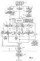
- the circuit architecture is partitioned into a pipeline composed of three primary segments, as distinguished by dashed lines in the schematic of Fig. 3.
- a first multiplication is performed involving the operand A and the partial operand B0.
- Thy second stage of performing the operation A*B+C involves the multiplication of A with the second, most significant segment, of operand B as represented by B1.
- each partial product A*BO and A*B1 has fewer bits than the product A*B. Namely, a full multiplication of A*B produces a product of 2N bits while the individual products of A*BO and A*B1 are composed of approximately 1.5N bits.
- An architecture and sequence of operation of the present form, involving multiple cycles through the same multiplier, has a significant effect on the size of a Wallace tree multiplier. Even though the bit count decreased by 25%, the number of CSA's in the multiplier decreases by approximately 50%.
- the preferred embodiment of the present invention provides for a major reduction in the size of the multiplier.
- the invention employs a Wallace tree with concurrent multiplication and addition resources. Thereby, aligned operand C can be added to appropriate bits of A*BO distinct from the final addition of A*B1 with the most significant bits of A•B0.
- the benefits ascribed to multiplication according to the method depicted in Fig. 2 are provided in the circuit architecture of Fig. 3.
- the architecture is divided into three segments individualized by dashed lines 1 and 2 in Fig. 3.
- the three segments represent three stages of a pipeline which performs the mathematical operation A*B+C in a nominal two cycle sequence while using significantly smaller circuits to perform the functions of the full adder and multiplier.
- the mantissas of operands A, B and C are provided by file register 3.
- the exponents are manipulated elsewhere in fairly well known manner to enable alignment shifter/inverter 4.
- separate logic is used to handle the signs of operands A, B and C in a manner which eventually leads to the appropriate sign in sign bit position 6 of incrementer 23.
- operand in the ensuing paragraphs will refer generally to the mantissa of each of the operands A, Band C, in that the mantissas are the primary subjects of the manipulations being accomplished.
- Operands A and C are latched into respective latches 7 and 8 while operand B is split by multiplexer 9 before storage in latch 11. Following such latching the respective value of BO or B1 are translated by booth encoder 12 and conveyed to multiplier 13.
- Multiplier 13 preferably employs a Wallace tree configuration capable of simultaneously multiplying a 53 bit operand with a 28 bit operand while adding 3 further operands.
- Wallace trees composed of carry save adders (CSA) are described in the aforementioned U.S. Patents 4,969,118 and 4,999,802, and in the text book by Patterson et al. Booth encoding is discussed in the noted text by Patterson et al as well as described in the aforementioned IBM Technical Disclosure Bulletin.
- multiplier 13 receives inputs bits representing operand A, encoded bits representing BO or B1, shift aligned least significant bits from operand C, and sum and carry bits from an immediately preceding cycle.
- multiplier 13 in Fig. 3 receives the appropriately shifted low end bits of operand C, operand A, operand B1, and the sum and carry values of the N/2 least significant bit: of the outcome from the previous multiplication involving A*BO.
- the next stage of the pipeline is isolated by latches 14, 16, 17 and 18 from the stage whose operation was just described. Note that latch 18 stores the results of the full addition of the least significant bits of the first multiplication, namely A*BO, with the appropriately shifted least significant bits of operand C.
- the primary function of the second stage of the pipeline depicted in Fig. 3 is to complete the full addition of the intermediate results. With reference to Fig. 2, this means the full addition of A*B1 with the most significant bits of A*BO as affected by shift aligned bits of operand C.
- the second stage of the pipeline as situated between boundary lines 1 and 2, includes LSB incrementer 19, full adder 21, logic gate 22, and MSB incrementer 23, together providing the 161 bit unrounded result to XOR 24.
- the effects of the sign of operand C are introduced into XOR gate 24 from sign bit location 6.
- the output of XOR gate 24 is held in latch 26. Note that in contrast to prior practices, full adder 21 provides an output of only 83 bits.
- the classical approach requires greater than 106 bits.
- LSB incrementer 19 manipulates the 28 least significant bits of the 161 bit result. The 50 most significant bits of the result are manipulated by MSB incrementer 23. Further note that LSB incrementer 19 provides a carry to adder 21, which adder itself provides a selective carry, via gate 22, to MSB incrementer 23, which incrementer then closes the loop by providing an end around carry to the input of LSB incrementer 19.
- LSB incrementer 19 to handle the N/2 least significant bits arose from the recognition that data manipulation according to the present architecture involves only a single carry bit as the input to the least significant bit position of the composite 161 bit output.
- Example #1 shows a 1's complement manipulation of the decimal values 6, 10, 11, -6 and -11 in binary form. 1's complement addition of selected numbers as appears in Example #1 illustrates that the circuitry must in- dude the ability to provide an end around carry from the most significant bit position to the least significant bit position. See the example addition of 10 with -6.
- gate 22 The purpose of gate 22 is to selectively delete carry bits propagating from adder 21 to MSB incrementer 23. Carry bits are selectively deleted when the C operand is shifted so that the bits align with the sign position in the partial products from the Wallace tree multiplier.
- the constraints for dropping a carry bit are defined by the three examples which follow.
- the Wallace tree multiplier composed of carry save adders, combines three inputs to provide a sum output and a carry output, the result of which is then further added in a successive stage of the Wallace tree multiplier to an aligned value of the C operand (C i ).
- the X symbol identifies a bit position omitted from C because it aligns with the sign position of the multiplied values.
- the output of the Wallace tree is composed of sum and carry binary bits, which themselves are the two inputs to a full adder. Note that the result of the full adder would propagate a "1" bit into the sign bit position.
- gate 22 is disabled to delete such carry bit before it propagates into the MSB incrementer.
- the example identified as #4 illustrates addition with a C 3 operand value during which gate 22 propagates a carry from adder 21 to MSB incrementer 23.
- the carry bit resulting from the operation preceding the full add is again dropped, but when followed by a second carry during the full add, such second carry is propagated to the next most significant bit.
- the carry generated in adder 21 is conveyed only when appropriate to increment the C value as previously entered into MSB incrementer 23.
- the 161 bit result held in latch 26 is normalized and rounded in block 27 following relatively conventional practices and before being provided as a 53 bit output equal to the mathematical operation defined as A*B+C.
- the pipelined architecture of the preferred embodiment provides for concurrence of operations in a manner which optimizes the incremental multiplication of A*B. Partitioned multiplication and time interleaved addition allow the use of a smaller multiplier and an incrementer to replace a large number of the least significant bits of the full adder. Finally, the preferred embodiment includes resources for selectively deleting carry bits, which bits would otherwise propagate from the full adder into the most significant bit incrementer when conditions dictate that the propagation is not appropriate.
Abstract
An electronic circuit is disclosed for performing the floating point arithmetic operation A*B+C. The multiplication is accomplished in two or more stages, each stage involving corresponding sets of partial products and concurrently accomplished incremental summations. A pipelined architecture provides for the summation of the least significant bits of an intermediate product with operand C at a stage preceding entry into a full adder. Thereby, a significant portion of the full adder can be replaced by a simpler and smaller incrementer circuit. Partitioning of the multiplication operation into two or more partial product operations proportionally reduces the size of the multiplier required. Pipelining and concurrence execution of multiplication and addition operation in the multiplier provides in two cycles the results of the mathematical operation A*B+C while using a full adder of three-quarters normal size.
Description
- This invention relates generally to electronic circuits and more specifically to electronic circuits for performing floating point arithmetic functions.
- A variety of circuit configurations (hereafter referred to as architectures) are known and in use for performing floating point calculations in digital computers. Given the complexity of floating point calculations and the sizes of typical operands, where for scientific applications mantissas nominally are composed of greater than 50 bits, there exists an acute need for an architecture which retains the scientific precision yet reduces the circuit complexity. This is particularly true in the competitive market of workstations, where computer designers strive to provide the workstation user with the greatest degree of computational capability while minimizing the cost and size of the hardware.
- The classical floating point arithmetic operation to which the present invention is directed involves, in succession, the multiplication of two operands followed by the addition of the resultant with a third operand, mathematically described as A*B+C. The significance of this mathematical computation can be gleaned from the discussion in U.S. Patent No. 4,969,118. Though highly flexible in usage, the mathematical operation of A*B+C exacts a significant toll as far as circuit complexity when implemented in a conventional architecture. The problems arises from the fact the final stage adder must be capable of handling a full 3N bits to ensure that the outcome retains the precision attributed to the individual N bit operands. Thus for our representative 50 bit operand, the full adder must be capable of handling greater than 150 bits. An example of such an architecture appears in U.S. Patent No. 4,999,802.
- A full adder with resources to provide an output having a bit count in the range of 150 is very large and will therefore likely consume a significant portion of any integrated circuit chip upon which it resides. The architecture in U.S. Patent No. 4,999,802 is made more efficient by selectively pipelining operations to improve the overall performance of the floating point arithmetic unit in situations where the results of the first operation are determined to be operands in a successive operation.
- One floating point architecture refinement which reduces the size of the full adder uses an incrementer for the upper third most significant bits. Examples of such configurations appear in U.S. Patent No. 4,969,118 and IBM Technical Disclosure Bulletin, Volume 30, No. 3, August 1987, pages 982-987. Thus, an incrementer of size N reduces the size of the full adder in a proportional amount, leaving the adder to be 2N for N size operands in the calculation of A*B+C. Incrementers are known to be significantly smaller than adders, in that they merely take a carry-in signal and propagate the result to more significant bit positions. As shown in U.S. Patent No. 4,969,118, the carry-out of the incrementer becomes an end around carry back to the carry-in of the adder.
- The electronic devices needed to perform the multiplication stage of the arithmetic operation A*B+C are similarly complex for operands having large values of N. Contemporary high speed floating point multiplication architectures use Wallace trees, composed of carry save adders (CSAs) configured in arrays, to provide an outpoint having 2N bits for two operands individually composed of N bits. Examples of such appear in U.S. Patents No. 4,969,118 and 4,999,802, as well as the aforementioned IBM Technical Disclosure Bulletin, and in the text bookentitiedComputer Architecture A Quantitative Approach by D. A. Patterson et ai, Copyright 1990, PagesA-42 through A-49. There is suggestion in the text book by Patterson et al that the multiplier array could he reduced in size through the practice of multiple passes.
- In the context of such teaching, there remains a need for a floating point architecture, and a related method of use, in which the full adder is further reduced in size, the multiplier arrays is reduced in size, and pipelining is implemented to overlap multiplication and addition operations.
- Accordingly the present invention provides an electronic circuit for performing a floating point arithmetic operation (A*B+C), the mantissas of operands A, B and C each comprising N bits, the electronic circuit comprising: a file register for providing each mantissa to an associated latch, the mantissa of operand B being split into N/M portions (where M is a whole number> 1) before being received by its associated latch; a multiplier adapted to receive input bits from the latches representing the mantissa of A, the portions of the mantissa B and a number of least significant bits (LSBs) from mantissa C, and for performing a sequence of multiplication functions on said bits; an adder for receiving the output of the multiplication functions performed by the multiplier; a first incrementer for receiving the LSBs from the multiplication functions and a second incrementer for receiving the remaining bits of mantissa C not received by the multiplier; the adder and the incrementers cooperating to produce a result from which the product A*B+C can be derived.
- It will be apparent that the present invention provides an electronic circuit capable of performing the floating point arithmetic operation ofA*B+C, in which the mantissas of the operands are N bits, the circuit having: means for generating a first partial product using the operand Aand a fraction N/M (wherein M is a whole number greater than 1) of the least significant bits of operand B; means for generating a second partial product of operand A and the next N/M bits of operand B; means for summing operand C with the first partial product and providing selected bits of that result to a first incrementer suitable for receiving a fractional part [N(M-1)]/M of the least significant bits of the arithmetic operation, and means for summing selected most significant bits from the first partial product with selected most significant bits from the second partial product in an adder capable of providing a sum composed of significantly fewer than 2N hits (2N - N(M-1)/M bit adder).
- In one variation, carry-out bits from the adder are provided as carry-in bits to the second incrementer, which second incrementer provides its carry-out bits as end around carry bits to the first incrementer. The invention further contemplates steps in which a first partial product is generated using operand A and the least significant bits of operand B, selected bits from the result are added to operand Cforentry into a least significant bit incrementer, and selected most significant bits from the first partial product are summed with selected most significant bits from a second partial product in the adder.
- In a preferred embodiment, the invention relates to an electronic circuit which performs the floating point arithmetic operation of A*B+C using a multiplier array, a reduced size adder, two incrementers, and an incrementer-to- incrementer end around carry, in a two-cycle sequence. The architecture provides for pipelined data manipulation in which, during a first cycle, operand A is multiplied by a fraction of operand B. The least significant bits of the outcome are added to appropriately shifted bits of operand C. During the second cycle, operand A is multiplied with the remaining bits of operand B, added to aligned bits of operand C, and combined with bits from the prior multiplication cycle using one adder and two incrementers. The adder receives a carry from the least significant bit (LSB) incrementer and provides a carry to the most significant bit (MSB) incrementer. The use of two cycles and a LSB incrementer significantly reduces the sizes of both the multiplier array and the full adder.
- The present invention will be described further, by way of example only, with reference to an embodiment thereof as illustrated on the accompanying drawings, in which:
- Fig.1 schematically depicts bit positions of operands in a classic floating point multiplication.
- Fig.2 schematically depicts the orientation of bits according to the preferred embodiment of the present invention.
- Fig.3 schematically depicts by block diagram a preferred architecture for the floating point multiplier of the preferred embodiment of the present invention.
- Fig. 1 schematically depicts the classical approach to performing a floating point operation defined by the mathematical relationship A*B+C, where A, B and C are individually composed of N bits (N = 53). It should be apparent that the mantissa of operand C must be added before the truncation or rounding of the intermediate resultA*B. Thus the intermediate result of A*B is composed of 106 bits, including 2 further bit places for carry conditions. Following classical practices, the 53 bits of operand C are added to the 108 bits of the A*B result following alignment of the C mantissa with theA*B mantissa. The alignment range of C is shown by the dashed lines in Fig.1. Following such alignment, the two values A*B and C are added in a full adder having an output of 161 bits. The S bit at the left represents the sign of the value C, with the sign of the A*B product being handled by separate logic. The XOR is then used to provide the correct 1's complement value from the 161 bit full adder.
- Those skilled in the design of electronic circuits for full addition and multiplication know that full adders are very large and complicated devices. There are clear benefits to be gained if the bit size of the full adder can be reduced. Similarly, a distinct reduction in circuit size can be gained if the Wallace tree multiplier, typically composed of multiple CSAs, can be reduced in bit count.
- The earlier noted U.S. Patent 4,969,118 suggests that for the mathematical operation of A*B+C, where operands A, Band C are each N bits, an N bit incrementer can be used in the most significant bit (MSB) position of the full adder to reduce the size of adder from 3N to 2N. A similar approach is discussed in the aforementioned IBM Technical Disclosure Bulletin. The architecture according to the preferred embodiment of the present invention further reduces the size of the full adder by the use of an incrementer to replace operations performed in the least significant bit (LSB) side of the full adder, and as an aspect thereof, also reduces in size the Wallace tree multiplier. Central to the refined approach is the partition of the multiplication operation into multiple cycles, and the selective addition of partial products in the multiple cycles using a pipelined architecture.
- Fig. 2 conceptually depicts the operations associated with a preferred embodiment of the invention. Again, operands A, B and C are composed of N bits (where N = 53), and operand B is divided into M segments in which M is a whole number greater than 1. In the illustration M is equal to 2. The circuit architecture is partitioned into a pipeline composed of three primary segments, as distinguished by dashed lines in the schematic of Fig. 3. In the context of Fig. 2, a first multiplication is performed involving the operand A and the partial operand B0. Thy second stage of performing the operation A*B+C involves the multiplication of A with the second, most significant segment, of operand B as represented by B1. However, since the least significant, bits of operation of A*BO are fixed, the value of C as appropriately shifted can also be added into the least significant bit range of the final result. Since these bit ranges of the final result are not directly affected by the outcome of the multiplication A*B1, the second multiplication can be accomplished concurrent with the first addition. The framework for a pipelined architecture is thereby defined.
- For the specific example in Fig. 2, the addition of the N/2 least significant bits is accomplished at the same time that the circuit is performing the second multiplication. It should also be apparent that the concept depicted in Fig. 2 can be extended to larger subdivisions of operand B, and the associated pipelined or concurrent multiplication and addition operations of partial results. Unfortunately, the returns diminish as the value of M, the divisor of operand B, increases. For example, for M = 2, the full adder must accommodate all the bits of A*B1. In this example the full adder is 2N - N/2 size. However, the adder decreases in size at a diminishing rate as M increases, as defined by the formula 2N - N(M-1)/M.
- The use of partial products according to the procedure depicted in Fig. 2 has little consequence unless one appreciates that the least significant bits of the addition of A*BO with the appropriately shifted bits of operand C are not subject to changes as a direct consequence of subsequent multiplications. Therefore, these bits can be manipulated in a device less complex than a full adder.
- Another fallout of the operation can be understood upon recognizing that each partial product A*BO and A*B1 has fewer bits than the product A*B. Namely, a full multiplication of A*B produces a product of 2N bits while the individual products of A*BO and A*B1 are composed of approximately 1.5N bits. An architecture and sequence of operation of the present form, involving multiple cycles through the same multiplier, has a significant effect on the size of a Wallace tree multiplier. Even though the bit count decreased by 25%, the number of CSA's in the multiplier decreases by approximately 50%. Thus, the preferred embodiment of the present invention provides for a major reduction in the size of the multiplier. As embodied in Fig 3, the invention employs a Wallace tree with concurrent multiplication and addition resources. Thereby, aligned operand C can be added to appropriate bits of A*BO distinct from the final addition of A*B1 with the most significant bits of A•B0.
- The benefits ascribed to multiplication according to the method depicted in Fig. 2 are provided in the circuit architecture of Fig. 3. The architecture is divided into three segments individualized by dashed
lines 1 and 2 in Fig. 3. The three segments represent three stages of a pipeline which performs the mathematical operation A*B+C in a nominal two cycle sequence while using significantly smaller circuits to perform the functions of the full adder and multiplier. The mantissas of operands A, B and C are provided byfile register 3. The exponents are manipulated elsewhere in fairly well known manner to enable alignment shifter/inverter 4. Similarly, separate logic is used to handle the signs of operands A, B and C in a manner which eventually leads to the appropriate sign insign bit position 6 ofincrementer 23. The term "operand" in the ensuing paragraphs will refer generally to the mantissa of each of the operands A, Band C, in that the mantissas are the primary subjects of the manipulations being accomplished. - Operands A and C are latched into
respective latches multiplexer 9 before storage inlatch 11. Following such latching the respective value of BO or B1 are translated bybooth encoder 12 and conveyed tomultiplier 13.Multiplier 13 preferably employs a Wallace tree configuration capable of simultaneously multiplying a 53 bit operand with a 28 bit operand while adding 3 further operands. Wallace trees composed of carry save adders (CSA) are described in the aforementioned U.S. Patents 4,969,118 and 4,999,802, and in the text book by Patterson et al. Booth encoding is discussed in the noted text by Patterson et al as well as described in the aforementioned IBM Technical Disclosure Bulletin. - As depicted in Fig. 3,
multiplier 13 receives inputs bits representing operand A, encoded bits representing BO or B1, shift aligned least significant bits from operand C, and sum and carry bits from an immediately preceding cycle. Thus, in the context of the second multiplication accomplished according to the sequence in Fig. 2,multiplier 13 in Fig. 3 receives the appropriately shifted low end bits of operand C, operand A, operand B1, and the sum and carry values of the N/2 least significant bit: of the outcome from the previous multiplication involving A*BO. The next stage of the pipeline is isolated bylatches latch 18 stores the results of the full addition of the least significant bits of the first multiplication, namely A*BO, with the appropriately shifted least significant bits of operand C. - The primary function of the second stage of the pipeline depicted in Fig. 3 is to complete the full addition of the intermediate results. With reference to Fig. 2, this means the full addition of A*B1 with the most significant bits of A*BO as affected by shift aligned bits of operand C. The second stage of the pipeline, as situated between
boundary lines 1 and 2, includesLSB incrementer 19,full adder 21,logic gate 22, andMSB incrementer 23, together providing the 161 bit unrounded result toXOR 24. The effects of the sign of operand C are introduced intoXOR gate 24 fromsign bit location 6. The output ofXOR gate 24 is held inlatch 26. Note that in contrast to prior practices,full adder 21 provides an output of only 83 bits. The classical approach requires greater than 106 bits. Accordingly, the size ofadder 21 is reduced significantly.LSB incrementer 19 manipulates the 28 least significant bits of the 161 bit result. The 50 most significant bits of the result are manipulated byMSB incrementer 23. Further note thatLSB incrementer 19 provides a carry to adder 21, which adder itself provides a selective carry, viagate 22, toMSB incrementer 23, which incrementer then closes the loop by providing an end around carry to the input ofLSB incrementer 19. - The use of LSB incrementer 19 to handle the N/2 least significant bits arose from the recognition that data manipulation according to the present architecture involves only a single carry bit as the input to the least significant bit position of the composite 161 bit output.
- Example #1 shows a 1's complement manipulation of the

decimal values - The purpose of
gate 22 is to selectively delete carry bits propagating fromadder 21 toMSB incrementer 23. Carry bits are selectively deleted when the C operand is shifted so that the bits align with the sign position in the partial products from the Wallace tree multiplier. The constraints for dropping a carry bit are defined by the three examples which follow. -

- In the example identified as #2, the Wallace tree multiplier, composed of carry save adders, combines three inputs to provide a sum output and a carry output, the result of which is then further added in a successive stage of the Wallace tree multiplier to an aligned value of the C operand (Ci). The X symbol identifies a bit position omitted from C because it aligns with the sign position of the multiplied values. The output of the Wallace tree is composed of sum and carry binary bits, which themselves are the two inputs to a full adder. Note that the result of the full adder would propagate a "1" bit into the sign bit position. According to the preferred embodiment of the
present invention gate 22 is disabled to delete such carry bit before it propagates into the MSB incrementer. -

- A similar situation exists for the example identified as #3. In this case a C2 operand value is added. Again, the carry bit is dropped when it enters the sign location, but now this occurs during addition preceding the full add cycle.
-


- The example identified as #4 illustrates addition with a C3 operand value during which
gate 22 propagates a carry fromadder 21 toMSB incrementer 23. In this situation, the carry bit resulting from the operation preceding the full add is again dropped, but when followed by a second carry during the full add, such second carry is propagated to the next most significant bit. In this way, the carry generated inadder 21 is conveyed only when appropriate to increment the C value as previously entered intoMSB incrementer 23. - In keeping with the architecture define in Fig. 3, the 161 bit result held in
latch 26 is normalized and rounded inblock 27 following relatively conventional practices and before being provided as a 53 bit output equal to the mathematical operation defined as A*B+C. - It should be apparent from the description that the pipelined architecture of the preferred embodiment provides for concurrence of operations in a manner which optimizes the incremental multiplication of A*B. Partitioned multiplication and time interleaved addition allow the use of a smaller multiplier and an incrementer to replace a large number of the least significant bits of the full adder. Finally, the preferred embodiment includes resources for selectively deleting carry bits, which bits would otherwise propagate from the full adder into the most significant bit incrementer when conditions dictate that the propagation is not appropriate.
Claims (10)
1. An electronic circuit for performing a floating point arithmetic operation (A*B+C), the mantissas of operands A, B and C each comprising N bits, the electronic circuit comprising:
a file register (3) for providing each mantissa to an associated latch (7, 8, 11), the mantissa of operand B being split into N/M portions (where M is a whole number > 1) before being received by its associated latch (11);
a multiplier (13) adapted to receive input bits from the latches representing the mantissa of A, the portions of the mantissa B and a number of least significant bits (LSBs) from mantissa C, and for performing a sequence of multiplication functions on said bits; an adder (21) for receiving the output of the multiplication functions performed by the multiplier (13); a first incrementer (19) for receiving the LSBs from the multiplication functions and a second incrementer (23) for receiving the remaining bits of mantissa C not received by the multiplier(13); the adder (21) and the incrementers (19, 23) cooperating to produce a result from which the product A*B+C can be derived.
2. An electronic circuit as claimed in Claim 1, in which the adder (21) provides carry bits to the second incrementer (23) and receives carry bits from the first incrementer (19).
3. An electronic circuit as claimed in Claim 1 or Claim 2, wherein the adder (21) is a carry look ahead adder.
4. An electronic circuit as claimed in any preceding claim wherein the mantissa of operand B is split in a multiplexer (9).
5. An electronic circuit as claimed in any preceding claim, wherein the result produced by the adder (21) and incrementers (19, 23) is passed through a XOR gate (24) with a bit (6) indicating the sign of mantissa C, and the output is normalized and rounded to produce the product A*B+C.
6. An electronic circuit as claimed in any preceding claim wherein M=2.
7. A method for performing a floating point arithmetic operation (A*B+C), wherein the mantissas are composed of N bits, comprising the steps of:
generating a first partial product in a multiplier using A and N/M (M is a whole number>1) of the least significant bits of B;
generating a second partial product in the multiplier using A and the next N/M bits of B;
summing C with the first partial product and providing selected bits from the result to a first incre-
menter receiving the 
least significant bits of the arithmetic operation; and summing selected most significant bits from the first partial product with selected most significantbits from the second partial product in a 
bit adder.
8. A method as claimed in Claim 7, including the further steps of:
transferring carry bits from the first incrementer to the adder, and
transferring carry bits from the adder to a second incrementer.
9. A method as claimed in Claim 7 or Claim 8 wherein the step of summing C with the first partial product and the step of generating a second partial product are accomplished substantially concurrently.
10. A method as claimed in any of Claims 7 to 9, further including the step of selectively removing data in transit from the adder to the second incrementer.
Applications Claiming Priority (2)
| Application Number | Priority Date | Filing Date | Title |
|---|---|---|---|
| US807697 | 1991-12-16 | ||
| US07/807,697 US5241493A (en) | 1991-12-16 | 1991-12-16 | Floating point arithmetic unit with size efficient pipelined multiply-add architecture |
Publications (2)
| Publication Number | Publication Date |
|---|---|
| EP0547835A2 true EP0547835A2 (en) | 1993-06-23 |
| EP0547835A3 EP0547835A3 (en) | 1993-08-18 |
Family
ID=25196981
Family Applications (1)
| Application Number | Title | Priority Date | Filing Date |
|---|---|---|---|
| EP19920311237 Withdrawn EP0547835A3 (en) | 1991-12-16 | 1992-12-09 | An electronic circuit for performing floating point arithmetic functions |
Country Status (3)
| Country | Link |
|---|---|
| US (1) | US5241493A (en) |
| EP (1) | EP0547835A3 (en) |
| JP (1) | JPH05233228A (en) |
Cited By (1)
| Publication number | Priority date | Publication date | Assignee | Title |
|---|---|---|---|---|
| GB2341702A (en) * | 1998-08-20 | 2000-03-22 | Advanced Risc Mach Ltd | Floating-point multiply-accumulate unit |
Families Citing this family (31)
| Publication number | Priority date | Publication date | Assignee | Title |
|---|---|---|---|---|
| US6441842B1 (en) * | 1992-02-19 | 2002-08-27 | 8×8, Inc. | Video compression/decompression processing and processors |
| EP0645699A1 (en) * | 1993-09-29 | 1995-03-29 | International Business Machines Corporation | Fast multiply-add instruction sequence in a pipeline floating-point processor |
| US5418736A (en) * | 1994-03-11 | 1995-05-23 | Nexgen, Inc. | Optimized binary adders and comparators for inputs having different widths |
| US6385634B1 (en) | 1995-08-31 | 2002-05-07 | Intel Corporation | Method for performing multiply-add operations on packed data |
| US7395298B2 (en) * | 1995-08-31 | 2008-07-01 | Intel Corporation | Method and apparatus for performing multiply-add operations on packed data |
| US5867413A (en) * | 1995-10-17 | 1999-02-02 | Hitachi Micro Systems, Inc. | Fast method of floating-point multiplication and accumulation |
| US5880983A (en) * | 1996-03-25 | 1999-03-09 | International Business Machines Corporation | Floating point split multiply/add system which has infinite precision |
| US5790445A (en) * | 1996-04-30 | 1998-08-04 | International Business Machines Corporation | Method and system for performing a high speed floating point add operation |
| US5790444A (en) * | 1996-10-08 | 1998-08-04 | International Business Machines Corporation | Fast alignment unit for multiply-add floating point unit |
| JP3790307B2 (en) | 1996-10-16 | 2006-06-28 | 株式会社ルネサステクノロジ | Data processor and data processing system |
| US5928316A (en) * | 1996-11-18 | 1999-07-27 | Samsung Electronics Co., Ltd. | Fused floating-point multiply-and-accumulate unit with carry correction |
| US5796644A (en) * | 1996-11-18 | 1998-08-18 | Samsung Electronics Company, Ltd. | Floating-point multiply-and-accumulate unit with classes for alignment and normalization |
| US6205459B1 (en) * | 1996-12-18 | 2001-03-20 | Yamaha Corporation | Digital signal processor and digital signal processing system incorporating same |
| US5880984A (en) * | 1997-01-13 | 1999-03-09 | International Business Machines Corporation | Method and apparatus for performing high-precision multiply-add calculations using independent multiply and add instruments |
| US6061707A (en) * | 1998-01-16 | 2000-05-09 | International Business Machines Corporation | Method and apparatus for generating an end-around carry in a floating-point pipeline within a computer system |
| US6230257B1 (en) * | 1998-03-31 | 2001-05-08 | Intel Corporation | Method and apparatus for staggering execution of a single packed data instruction using the same circuit |
| US6230253B1 (en) | 1998-03-31 | 2001-05-08 | Intel Corporation | Executing partial-width packed data instructions |
| US6381624B1 (en) * | 1999-04-29 | 2002-04-30 | Hewlett-Packard Company | Faster multiply/accumulator |
| US6571266B1 (en) * | 2000-02-21 | 2003-05-27 | Hewlett-Packard Development Company, L.P. | Method for acquiring FMAC rounding parameters |
| US7430578B2 (en) | 2001-10-29 | 2008-09-30 | Intel Corporation | Method and apparatus for performing multiply-add operations on packed byte data |
| JP3845009B2 (en) * | 2001-12-28 | 2006-11-15 | 富士通株式会社 | Product-sum operation apparatus and product-sum operation method |
| US7590677B2 (en) * | 2002-03-11 | 2009-09-15 | Texas Instruments Incorporated | Processor with summation instruction using overflow counter |
| US7519647B2 (en) | 2005-02-09 | 2009-04-14 | International Business Machines Corporation | System and method for providing a decimal multiply algorithm using a double adder |
| US7739324B1 (en) | 2006-03-22 | 2010-06-15 | Cadence Design Systems, Inc. | Timing driven synthesis of sum-of-product functional blocks |
| US20080071852A1 (en) * | 2006-09-14 | 2008-03-20 | International Business Machines Corporation | Method to perform a subtraction of two operands in a binary arithmetic unit plus arithmetic unit to perform such a method |
| US20090112963A1 (en) * | 2007-10-29 | 2009-04-30 | International Business Machines Corporation | Method to perform a subtraction of two operands in a binary arithmetic unit plus arithmetic unit to perform such a method |
| US20100125621A1 (en) * | 2008-11-20 | 2010-05-20 | Advanced Micro Devices, Inc. | Arithmetic processing device and methods thereof |
| US8495121B2 (en) * | 2008-11-20 | 2013-07-23 | Advanced Micro Devices, Inc. | Arithmetic processing device and methods thereof |
| GB201508635D0 (en) * | 2015-05-20 | 2015-07-01 | Ibm | Multiply-and-accumulate unit in carry-save adder format and application in a feedback loop equalizer |
| US9952829B2 (en) * | 2016-02-01 | 2018-04-24 | International Business Machines Corporation | Binary fused multiply-add floating-point calculations |
| US11163531B2 (en) * | 2018-07-28 | 2021-11-02 | Dsp Group Ltd. | Multiply and accumulate (MAC) unit and a method of adding numbers |
Citations (1)
| Publication number | Priority date | Publication date | Assignee | Title |
|---|---|---|---|---|
| EP0377837A2 (en) * | 1989-01-13 | 1990-07-18 | International Business Machines Corporation | Floating point unit having simultaneous multiply and add |
Family Cites Families (9)
| Publication number | Priority date | Publication date | Assignee | Title |
|---|---|---|---|---|
| US4190894A (en) * | 1978-03-10 | 1980-02-26 | Digital Equipment Corporation | High speed parallel multiplication apparatus with single-step summand reduction |
| US4228520A (en) * | 1979-05-04 | 1980-10-14 | International Business Machines Corporation | High speed multiplier using carry-save/propagate pipeline with sparse carries |
| EP0086904B1 (en) * | 1982-02-18 | 1985-11-21 | Deutsche ITT Industries GmbH | Digital parallel calculating circuit for positive and negative binary numbers |
| JPS60200338A (en) * | 1984-03-23 | 1985-10-09 | Yokogawa Medical Syst Ltd | Mantissa part multiplier of floating point multiplier |
| JPS6284335A (en) * | 1985-10-09 | 1987-04-17 | Hitachi Ltd | Multiplier circuit |
| US4910701A (en) * | 1987-09-24 | 1990-03-20 | Advanced Micro Devices | Split array binary multiplication |
| US4996661A (en) * | 1988-10-05 | 1991-02-26 | United Technologies Corporation | Single chip complex floating point numeric processor |
| US4999802A (en) * | 1989-01-13 | 1991-03-12 | International Business Machines Corporation | Floating point arithmetic two cycle data flow |
| JPH0831024B2 (en) * | 1989-02-03 | 1996-03-27 | 日本電気株式会社 | Arithmetic processor |
-
1991
- 1991-12-16 US US07/807,697 patent/US5241493A/en not_active Expired - Fee Related
-
1992
- 1992-11-13 JP JP4304203A patent/JPH05233228A/en active Pending
- 1992-12-09 EP EP19920311237 patent/EP0547835A3/en not_active Withdrawn
Patent Citations (1)
| Publication number | Priority date | Publication date | Assignee | Title |
|---|---|---|---|---|
| EP0377837A2 (en) * | 1989-01-13 | 1990-07-18 | International Business Machines Corporation | Floating point unit having simultaneous multiply and add |
Non-Patent Citations (2)
| Title |
|---|
| IBM TECHNICAL DISCLOSURE BULLETIN. vol. 34, no. 7B, December 1991, NEW YORK US pages 283 - 285 , XP282581 ANON. 'Floating point 2:1 high level design' * |
| IEEE JOURNAL OF SOLID-STATE CIRCUITS vol. 25, no. 5, October 1990, NEW YORK US pages 1207 - 1212 , XP162804 HOKONEK ET AL 'Second-Generation RISC Floating Point with Multiply-Add Fused' * |
Cited By (3)
| Publication number | Priority date | Publication date | Assignee | Title |
|---|---|---|---|---|
| GB2341702A (en) * | 1998-08-20 | 2000-03-22 | Advanced Risc Mach Ltd | Floating-point multiply-accumulate unit |
| US6115729A (en) * | 1998-08-20 | 2000-09-05 | Arm Limited | Floating point multiply-accumulate unit |
| GB2341702B (en) * | 1998-08-20 | 2003-02-12 | Advanced Risc Mach Ltd | Floating point multiply-accumulate unit |
Also Published As
| Publication number | Publication date |
|---|---|
| EP0547835A3 (en) | 1993-08-18 |
| JPH05233228A (en) | 1993-09-10 |
| US5241493A (en) | 1993-08-31 |
Similar Documents
| Publication | Publication Date | Title |
|---|---|---|
| US5241493A (en) | Floating point arithmetic unit with size efficient pipelined multiply-add architecture | |
| US5272660A (en) | Method and apparatus for performing integer and floating point division using a single SRT divider in a data processor | |
| EP0377837B1 (en) | Floating point unit having simultaneous multiply and add | |
| USRE39385E1 (en) | Method and apparatus for performing mathematical functions using polynomial approximation and a rectangular aspect ratio multiplier | |
| US6446104B1 (en) | Double precision floating point multiplier having a 32-bit booth-encoded array multiplier | |
| Huang et al. | A new architecture for multiple-precision floating-point multiply-add fused unit design | |
| US8977670B2 (en) | Processor pipeline which implements fused and unfused multiply-add instructions | |
| US5633819A (en) | Inexact leading-one/leading-zero prediction integrated with a floating-point adder | |
| US5659495A (en) | Numeric processor including a multiply-add circuit for computing a succession of product sums using redundant values without conversion to nonredundant format | |
| JPH04227531A (en) | Pipeline floating-point processor | |
| Wang et al. | A survey of hardware designs for decimal arithmetic | |
| Naini et al. | 1 GHz HAL SPARC64/sup R/Dual Floating Point Unit with RAS features | |
| US5144576A (en) | Signed digit multiplier | |
| US5247471A (en) | Radix aligner for floating point addition and subtraction | |
| Arunachalam et al. | Efficient dual-precision floating-point fused-multiply-add architecture | |
| US9430190B2 (en) | Fused multiply add pipeline | |
| Vazquez et al. | Efficient implementation of parallel BCD multiplication in LUT-6 FPGAs | |
| US5574672A (en) | Combination multiplier/shifter | |
| JPH057737B2 (en) | ||
| US5867413A (en) | Fast method of floating-point multiplication and accumulation | |
| US5237525A (en) | In a data processor an SRT divider having a negative divisor sticky detection circuit | |
| Schwarz | Binary Floating-Point Unit Design: the fused multiply-add dataflow | |
| EP0840207A1 (en) | A microprocessor and method of operation thereof | |
| Nannarelli | A multi-format floating-point multiplier for power-efficient operations | |
| Fenwick | Introduction to computer data representation |
Legal Events
| Date | Code | Title | Description |
|---|---|---|---|
| PUAI | Public reference made under article 153(3) epc to a published international application that has entered the european phase |
Free format text: ORIGINAL CODE: 0009012 |
|
| AK | Designated contracting states |
Kind code of ref document: A2 Designated state(s): DE FR GB |
|
| PUAL | Search report despatched |
Free format text: ORIGINAL CODE: 0009013 |
|
| AK | Designated contracting states |
Kind code of ref document: A3 Designated state(s): DE FR GB |
|
| 17P | Request for examination filed |
Effective date: 19931021 |
|
| STAA | Information on the status of an ep patent application or granted ep patent |
Free format text: STATUS: THE APPLICATION HAS BEEN WITHDRAWN |
|
| 18W | Application withdrawn |
Withdrawal date: 19961022 |