EP0547802A2 - Wechselgetriebe - Google Patents
Wechselgetriebe Download PDFInfo
- Publication number
- EP0547802A2 EP0547802A2 EP92310960A EP92310960A EP0547802A2 EP 0547802 A2 EP0547802 A2 EP 0547802A2 EP 92310960 A EP92310960 A EP 92310960A EP 92310960 A EP92310960 A EP 92310960A EP 0547802 A2 EP0547802 A2 EP 0547802A2
- Authority
- EP
- European Patent Office
- Prior art keywords
- gear
- output
- assembly
- control
- input
- Prior art date
- Legal status (The legal status is an assumption and is not a legal conclusion. Google has not performed a legal analysis and makes no representation as to the accuracy of the status listed.)
- Withdrawn
Links
Images

Classifications
-
- F—MECHANICAL ENGINEERING; LIGHTING; HEATING; WEAPONS; BLASTING
- F16—ENGINEERING ELEMENTS AND UNITS; GENERAL MEASURES FOR PRODUCING AND MAINTAINING EFFECTIVE FUNCTIONING OF MACHINES OR INSTALLATIONS; THERMAL INSULATION IN GENERAL
- F16H—GEARING
- F16H29/00—Gearings for conveying rotary motion with intermittently-driving members, e.g. with freewheel action
- F16H29/02—Gearings for conveying rotary motion with intermittently-driving members, e.g. with freewheel action between one of the shafts and an oscillating or reciprocating intermediate member, not rotating with either of the shafts
- F16H29/04—Gearings for conveying rotary motion with intermittently-driving members, e.g. with freewheel action between one of the shafts and an oscillating or reciprocating intermediate member, not rotating with either of the shafts in which the transmission ratio is changed by adjustment of a crank, an eccentric, a wobble-plate, or a cam, on one of the shafts
-
- F—MECHANICAL ENGINEERING; LIGHTING; HEATING; WEAPONS; BLASTING
- F16—ENGINEERING ELEMENTS AND UNITS; GENERAL MEASURES FOR PRODUCING AND MAINTAINING EFFECTIVE FUNCTIONING OF MACHINES OR INSTALLATIONS; THERMAL INSULATION IN GENERAL
- F16H—GEARING
- F16H3/00—Toothed gearings for conveying rotary motion with variable gear ratio or for reversing rotary motion
- F16H3/44—Toothed gearings for conveying rotary motion with variable gear ratio or for reversing rotary motion using gears having orbital motion
- F16H3/72—Toothed gearings for conveying rotary motion with variable gear ratio or for reversing rotary motion using gears having orbital motion with a secondary drive, e.g. regulating motor, in order to vary speed continuously
-
- F—MECHANICAL ENGINEERING; LIGHTING; HEATING; WEAPONS; BLASTING
- F16—ENGINEERING ELEMENTS AND UNITS; GENERAL MEASURES FOR PRODUCING AND MAINTAINING EFFECTIVE FUNCTIONING OF MACHINES OR INSTALLATIONS; THERMAL INSULATION IN GENERAL
- F16H—GEARING
- F16H48/00—Differential gearings
- F16H48/06—Differential gearings with gears having orbital motion
- F16H48/08—Differential gearings with gears having orbital motion comprising bevel gears
Definitions
- This invention relates to a variable speed gear drive that selectively provides a variable output speed and direction from a constant speed power source.
- Prior art drives of this type have used a variety of different configurations to supply a constant output from a variable speed input source. Such examples typically use electronics and/or manual sensing means to gauge the varying ratios between the actual input and the desired constant output required orvice- a-versa.
- Variable output from a constant source can be seen in US-A-4,007,278, 4,109,551, 4,916,975 and CA-A-989644, FR-A-2,638,801 and FR-A-1,323,617.
- a variable drive transmission is disclosed using a carrier member mounted on a rotatable crank shaft with a number of spaced pivotally mounted segments that can selectively engage a central sprocket with multiple chain engagement sprockets rotatably secured to each segment.
- a variable speed transmission has a rotatable cage with a plurality of enclosed cranks.
- An annular cam is engaged by the cranks from which the selective output can be determined.
- US-A-4,077,278 is directed towards dividing input rotational force into two rotational components.
- An output differential combines the divided components rotational force.
- a gear arrangement has a pair of interconnected differential gear segments.
- CA-A-989644 a rotary mesh translating device is shown that uses two differentials with a self-locking rotary coupler.
- FR-A-2,638,801 is directed towards two differential mechanical power converters wherein the cage of the first differential receives input from a motor, converts same to output via interengaged gears to input shaft of the second differential with output from the cage of the second differential determined therefrom.
- a variable speed gear drive device having a constant input and a variable speed and directional output, comprising a first speed control gear assembly and a directional output gear assembly, said first speed control gear assembly comprising a plurality of interengaging gear pairs, an input drive shaft, a control gear rotatably coupled with said input shaft, an adjustable camming and drive assembly interconnected to said input shaft by transfer gears, said control gear selectively and intermittently driving said gear pairs on said input shaft, said camming and drive assembly comprising offset circular discs on respective cam discs, offset cams rotatably positioned on said offset circular discs, control discs extending from said input drive shaft, means on said cams for registration with said control discs, cam engagement arms with one-way clutch drive gears selectively engaged thereon, said directional gear assembly comprising first and second gear pairs on an output shaft, selective control input to said selective gear pairs and means for interconnecting said first and second gear pairs on said output shaft and said one-way clutch drive gears.
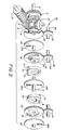
- a variable speed gear assembly has a speed selective gear configuration 11 and a directional gear assembly 12 interconnected therewith.
- the speed selective gear configuration 11 comprises an input and support shaft 13 on which is supported a plurality of interengaging gear pairs 14 and 15 and a control gear 16.
- Each of the gear pairs 14 and 15 is defined as having oppositely disposed matching gears 17 and 18 in the gear pair 14 and interengaging gears 19 and 20 in gear pair 15.
- the control gear 16 incrementally advances the gear 17 by selectively incremental rotation within the gear pairs 14 and 15 and associated input support shaft 13.
- the control gear 16 determines the rotation of the gear 17 that will occur as the result of the pair of interengaging gear pairs 14 and 15 under input on input and support shaft 13 indicated by an input arrow F.
- the control gear 16 is of a worm gear configuration.
- the interengaging gears 19 and 20 of the gear pair 15 are rotatably mounted on a central support shaft 21 which is integral with the input and support shaft 13. It will be evident from the above that each of the respective gears; 17, 18, 19 and 20 within each gear pair interengageably mesh with a respective gear of said adjacent gear pair in oppositely disposed relationship to one another. Since the support shaft 21 is driven directly by relative input to the drive and support shaft 13, it will rotate in a one-to-one relationship therewith. Repositioning the gear 17 will provide rotational output to the gear 18 and its output gear element 22 interengaged thereon.
- the input and support shaft 13 has three slotted control discs 23, 24 and 25 extending therefrom in spaced horizontal relation to one another.
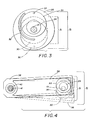
- the output gear element 22 is interconnected to an adjustable camming and variable drive assembly (A.C.D.), best seen in Figures 1 and 2.
- the A.C.D. comprises a pair of main camming discs 26 and 27 having respective cam parts 28 and 29 thereon in face-to-face relation.
- the camming discs 26 and 27 have a central bore therethrough and are rotatably positioned on the main input support shaft 13.
- the cam parts 28 and 29 are offset circular discs each having a circular cam 30 within an offset opening therein registerable with the respective cam parts 28 and 29.
- Control pins 31 extend from each of the cams 30 in oppositely disposed relation thereto.
- control pins 31 are registrable in the respective slotted control discs 23, 24 and 25, having control slots 23A, 24Aand B, and 25Atherein.
- Respective spiral access slots 32 in the cam discs 26 and 27, best seen in Figure 2 are aligned for access of respective control pins 31.
- the gear 18 and its output gear element 22 are interconnected to the respective cam discs 26 and 27 by a gear assembly 33 having a support shaft 34 and a plurality of spaced engagement gears 35, 36 and 37 thereon.
- a pair of bifurcated cam engagement arms 38 can be seen slideably engaging respective cams 30.
- the cam engagement arms 38 are journalled at 39 with one-way clutch bearings 40 within, as is well known in the art.
- a dual output gear 42 rotatably positioned on an output drive shaft 41 is engaged by the respective one-way clutch bearings 40 as hereinbefore described.
- Pairs of directional pairs of interengaging gear assemblies 43 and 44 are supported on oppositely disposed respective ends of the output shaft 41.
- the interengaging gear assembly43 has a secondary gear 45 and oppositely- disposed, bevelled matching gears 47 and 48 on a support shaft49 extending from and integral with said output drive shaft 41.
- the gear 45 acts as a directional control for the output of the output shaft 41.
- the gear assembly 44 has bevelled gears 50 and 51 on a support and control shaft 52 rotatably positioned on the output drive shaft 41.
- the output drive shaft 41 has a drive gear 53 that engages the bevelled gears 50 and 51 hereinbefore described.
- Figure 3 shows in solid and broken lines the relative positions of the cam discs 26 and 27, cam parts 28 and 29 and cams 30 illustrated at the maximum orbital path of the respective cam 30 indicated by line B.
- the cam 30 is also shown in dotted lines repositioned on the cam part 28 180° from its maximum orbital path on line B defining the minimal orbital path of the cams 30 illustrated by the line reference A.
- the bifurcated cam engagement arms 38 are illustrated engaging about the cams 30. With the relative orbital path increased, the resulting oscillation is transferred to the cam engagement arms 38 which either increases or decreases depending on the respective position of the cams 30 to the cam discs 26 and 27 (i.e. their orbital path A, and B). Since the cams 30 are always offset axially from one another, the rotational output of the arms (which is cyclable from each cam) is in effect constant to the respective dual output gears 42 as hereinbefore described.
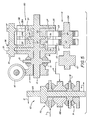
- the secondary output assembly 61 has a pair of secondary bifurcated cam engagement arms 63 driving a secondary output shaft 64 via a pair of one-way clutch bearings 65 and 66.
- a transfer worm gear 67 extends integrally from the secondary output shaft 64.
- the transfer worm gear 67 engages and drives an input gear 68 of the secondary directional gear assembly 62 as illustrated by an input arrow K therebetween.
- the secondary directional gear assembly 62 has a directional output shaft 69 that can be driven by either of two multiple gear assemblies 70 and 71.
- the secondary directional gear assembly 62 is identical to the directional gear assembly 12 of Figure 1 with the exception of the input gear 68 which in this alternative form takes the place of the dual output gear 42 of Figure 1, which is driven directly by the one-way clutch bearing 40.
- the secondary directional gear assembly 62 has directional control input arrows L and M on respective multiple interengaging gear assemblies 70 and 71 which in effect directs the directional output of the output shaft 69 indicated by the directional output arrows associated therewith N and O.
- the present device provides a variable drive transmission having incrementally adjusted speed control and output from a constant source with selective directional rotation output from two control elements.
- variable output can be achieved to the secondary directional gear assembly 62 via the worm gear 67 and input gear 68 to the output shaft 69.
Landscapes
- Engineering & Computer Science (AREA)
- General Engineering & Computer Science (AREA)
- Mechanical Engineering (AREA)
- Structure Of Transmissions (AREA)
Applications Claiming Priority (5)
| Application Number | Priority Date | Filing Date | Title |
|---|---|---|---|
| US07/807,192 US5169359A (en) | 1991-12-16 | 1991-12-16 | Constant/variable speed gear assembly |
| US807192 | 1991-12-16 | ||
| US07/963,439 US5308293A (en) | 1991-12-16 | 1992-10-19 | Variable speed drive transmission |
| US963439 | 1992-10-19 | ||
| CA002082591A CA2082591A1 (en) | 1991-12-16 | 1992-11-10 | Variable speed drive transmission |
Publications (2)
| Publication Number | Publication Date |
|---|---|
| EP0547802A2 true EP0547802A2 (de) | 1993-06-23 |
| EP0547802A3 EP0547802A3 (en) | 1993-09-08 |
Family
ID=27169241
Family Applications (1)
| Application Number | Title | Priority Date | Filing Date |
|---|---|---|---|
| EP19920310960 Withdrawn EP0547802A3 (en) | 1991-12-16 | 1992-12-01 | Variable speed drive transmission |
Country Status (3)
| Country | Link |
|---|---|
| US (1) | US5308293A (de) |
| EP (1) | EP0547802A3 (de) |
| CA (1) | CA2082591A1 (de) |
Cited By (1)
| Publication number | Priority date | Publication date | Assignee | Title |
|---|---|---|---|---|
| CN100567766C (zh) * | 2005-04-21 | 2009-12-09 | 艾顿株式会社 | 往复转动式发动机和动力传输设备及采用二者的混合系统 |
Families Citing this family (4)
| Publication number | Priority date | Publication date | Assignee | Title |
|---|---|---|---|---|
| US6537168B1 (en) | 2000-10-13 | 2003-03-25 | Kyung Soo Han | Variable speed transmission systems and rotary motion controls |
| US6926636B2 (en) | 2002-09-25 | 2005-08-09 | Jerry Luper | Gear driven power converter |
| US7731616B2 (en) * | 2005-08-05 | 2010-06-08 | Differential Dynamics Corporation | Variable motion control devices for transmission and other implementations and methods of use thereof |
| WO2011011358A2 (en) * | 2009-07-20 | 2011-01-27 | Kyung-Soo Han | A system and method for providing a constant output from a variable flow input |
Family Cites Families (22)
| Publication number | Priority date | Publication date | Assignee | Title |
|---|---|---|---|---|
| US1605886A (en) * | 1925-02-10 | 1926-11-02 | Getriebebau Ges Mit Beschraenk | Variable-feed gear |
| FR773636A (fr) * | 1932-12-19 | 1934-11-22 | Changement de vitesse à rapport de transmission variable sans échelons | |
| US2547453A (en) * | 1947-09-17 | 1951-04-03 | Joseph H Egy | Variable-speed transmission device |
| US3079812A (en) * | 1958-10-10 | 1963-03-05 | Liebel Flarsheim | Timer |
| FR1323617A (fr) * | 1962-02-27 | 1963-04-12 | Variateur de vitesse mécanique à couple variable | |
| CH403428A (de) * | 1962-07-09 | 1965-11-30 | Sig Schweiz Industrieges | Getriebe mit stufenlos veränderbarem Übersetzungsverhältnis |
| DE1910698A1 (de) * | 1969-03-03 | 1970-09-10 | Siegfried Witte | Stufenloses Getriebe |
| CA989644A (en) * | 1970-12-03 | 1976-05-25 | Thomas A.W.K. Watson | Rotary mechanical translating device |
| FR2327454A1 (fr) * | 1975-10-10 | 1977-05-06 | Combastet Michel | Convertisseur de couple |
| US4090413A (en) * | 1976-10-29 | 1978-05-23 | Ford Aerospace & Communications Corp. | Cyclic motion generator |
| US4109551A (en) * | 1977-01-12 | 1978-08-29 | Nemec Allen R | Variable speed gear ratio transmission apparatus |
| US4776236A (en) * | 1983-10-21 | 1988-10-11 | Gleasman Vernon E | No-slip, imposed differential |
| GB8511680D0 (en) * | 1985-05-09 | 1985-06-19 | Stidworthy F M | Variable phase & oscillatory drives |
| US4700589A (en) * | 1986-02-14 | 1987-10-20 | Coronel Paul K | Coronel radiant drive systems |
| US4916975A (en) * | 1986-04-24 | 1990-04-17 | Combastet M Michel | System for the control of the output speed of a torque converter with two differentials |
| US4729257A (en) * | 1986-07-28 | 1988-03-08 | Nelson Donald F | Balanced steerable transmission |
| US5108352A (en) * | 1988-08-15 | 1992-04-28 | Pires Paul B | Modified cranking mechanism for epicyclic transmission |
| FR2638801A1 (fr) * | 1988-11-09 | 1990-05-11 | Combastet Michel | Convertisseur de puissance |
| US4961719A (en) * | 1989-07-19 | 1990-10-09 | Gruber, Kaplan & Associates | Variable drive transmission |
| US5016493A (en) * | 1990-01-02 | 1991-05-21 | Han Kyung S | Variable speed gearing assembly |
| US5116292A (en) * | 1991-08-01 | 1992-05-26 | Han Kyung S | Variable drive transmission |
| US5169359A (en) * | 1991-12-16 | 1992-12-08 | Han Kyung S | Constant/variable speed gear assembly |
-
1992
- 1992-10-19 US US07/963,439 patent/US5308293A/en not_active Expired - Fee Related
- 1992-11-10 CA CA002082591A patent/CA2082591A1/en not_active Abandoned
- 1992-12-01 EP EP19920310960 patent/EP0547802A3/en not_active Withdrawn
Cited By (1)
| Publication number | Priority date | Publication date | Assignee | Title |
|---|---|---|---|---|
| CN100567766C (zh) * | 2005-04-21 | 2009-12-09 | 艾顿株式会社 | 往复转动式发动机和动力传输设备及采用二者的混合系统 |
Also Published As
| Publication number | Publication date |
|---|---|
| EP0547802A3 (en) | 1993-09-08 |
| CA2082591A1 (en) | 1994-05-11 |
| US5308293A (en) | 1994-05-03 |
Similar Documents
| Publication | Publication Date | Title |
|---|---|---|
| US7303497B1 (en) | Dual-input differential planetary gear transmission | |
| US6068570A (en) | Variable speed transmission system and differential | |
| US6537168B1 (en) | Variable speed transmission systems and rotary motion controls | |
| EP0159855A2 (de) | Stufenlose Fahrradgangschaltung | |
| US3919895A (en) | Variable output transmission | |
| US5116292A (en) | Variable drive transmission | |
| US7028572B2 (en) | Pitch transfer gear and transmissions | |
| US5016493A (en) | Variable speed gearing assembly | |
| US6055880A (en) | Transfer ring and gear arrangement for non-slip continuously variable transmission | |
| JP7751930B2 (ja) | 摩擦に依存しない均一的な入出力比を有する変速比無限大変速機 | |
| EP0547802A2 (de) | Wechselgetriebe | |
| US4817464A (en) | Frictionless continuously variable transmission | |
| AU762318B2 (en) | Multiple speed orbital transmission | |
| US4409862A (en) | Variable speed rotary power transmission | |
| AU660729B2 (en) | Variable speed drive transmission | |
| RU2147701C1 (ru) | Зубчато-рычажный вариатор | |
| US5169359A (en) | Constant/variable speed gear assembly | |
| WO1995000775A1 (en) | Variable ratio power transmission | |
| EP0116731A1 (de) | Fahrradgetriebe mit stufenloser Übersetzung | |
| EP0216540A1 (de) | Leistungsgetriebe für Drehbewegungsübertragung | |
| EP0647298A1 (de) | Antriebseinrichtung mit Freilauf | |
| EP1803971A1 (de) | Kugelübertragungseinheit für einen drehzahlwandler (varianten) und darauf basierendes stufengetriebe | |
| EP0299055A1 (de) | Differentialgetriebe mit taumelrädern. | |
| US20070238568A1 (en) | Cam-based infinitely variable transmission | |
| SU1019147A1 (ru) | Регулируема передача |
Legal Events
| Date | Code | Title | Description |
|---|---|---|---|
| PUAI | Public reference made under article 153(3) epc to a published international application that has entered the european phase |
Free format text: ORIGINAL CODE: 0009012 |
|
| AK | Designated contracting states |
Kind code of ref document: A2 Designated state(s): DE ES FR GB IT SE |
|
| PUAL | Search report despatched |
Free format text: ORIGINAL CODE: 0009013 |
|
| AK | Designated contracting states |
Kind code of ref document: A3 Designated state(s): DE ES FR GB IT SE |
|
| 17P | Request for examination filed |
Effective date: 19940224 |
|
| 17Q | First examination report despatched |
Effective date: 19950421 |
|
| 18D | Application deemed to be withdrawn |
Effective date: 19951102 |