EP0547638A1 - Screwing device - Google Patents
Screwing device Download PDFInfo
- Publication number
- EP0547638A1 EP0547638A1 EP92121652A EP92121652A EP0547638A1 EP 0547638 A1 EP0547638 A1 EP 0547638A1 EP 92121652 A EP92121652 A EP 92121652A EP 92121652 A EP92121652 A EP 92121652A EP 0547638 A1 EP0547638 A1 EP 0547638A1
- Authority
- EP
- European Patent Office
- Prior art keywords
- holding
- clamping
- fastening element
- fastening
- head
- Prior art date
- Legal status (The legal status is an assumption and is not a legal conclusion. Google has not performed a legal analysis and makes no representation as to the accuracy of the status listed.)
- Granted
Links
- 230000005484 gravity Effects 0.000 claims 1
- 125000006850 spacer group Chemical group 0.000 claims 1
- 238000003780 insertion Methods 0.000 description 10
- 230000037431 insertion Effects 0.000 description 10
- 238000011161 development Methods 0.000 description 5
- 238000013461 design Methods 0.000 description 3
- 230000000903 blocking effect Effects 0.000 description 2
- 238000006243 chemical reaction Methods 0.000 description 1
- 230000006835 compression Effects 0.000 description 1
- 238000007906 compression Methods 0.000 description 1
- 238000010276 construction Methods 0.000 description 1
- 238000006073 displacement reaction Methods 0.000 description 1
- 230000000694 effects Effects 0.000 description 1
- 230000002349 favourable effect Effects 0.000 description 1
- 238000000034 method Methods 0.000 description 1
- 230000000284 resting effect Effects 0.000 description 1
- 238000012549 training Methods 0.000 description 1
Images


Classifications
-
- B—PERFORMING OPERATIONS; TRANSPORTING
- B25—HAND TOOLS; PORTABLE POWER-DRIVEN TOOLS; MANIPULATORS
- B25B—TOOLS OR BENCH DEVICES NOT OTHERWISE PROVIDED FOR, FOR FASTENING, CONNECTING, DISENGAGING OR HOLDING
- B25B23/00—Details of, or accessories for, spanners, wrenches, screwdrivers
- B25B23/02—Arrangements for handling screws or nuts
- B25B23/08—Arrangements for handling screws or nuts for holding or positioning screw or nut prior to or during its rotation
- B25B23/10—Arrangements for handling screws or nuts for holding or positioning screw or nut prior to or during its rotation using mechanical gripping means
-
- B—PERFORMING OPERATIONS; TRANSPORTING
- B23—MACHINE TOOLS; METAL-WORKING NOT OTHERWISE PROVIDED FOR
- B23P—METAL-WORKING NOT OTHERWISE PROVIDED FOR; COMBINED OPERATIONS; UNIVERSAL MACHINE TOOLS
- B23P19/00—Machines for simply fitting together or separating metal parts or objects, or metal and non-metal parts, whether or not involving some deformation; Tools or devices therefor so far as not provided for in other classes
- B23P19/001—Article feeders for assembling machines
- B23P19/006—Holding or positioning the article in front of the applying tool
-
- B—PERFORMING OPERATIONS; TRANSPORTING
- B25—HAND TOOLS; PORTABLE POWER-DRIVEN TOOLS; MANIPULATORS
- B25B—TOOLS OR BENCH DEVICES NOT OTHERWISE PROVIDED FOR, FOR FASTENING, CONNECTING, DISENGAGING OR HOLDING
- B25B23/00—Details of, or accessories for, spanners, wrenches, screwdrivers
- B25B23/02—Arrangements for handling screws or nuts
- B25B23/04—Arrangements for handling screws or nuts for feeding screws or nuts
-
- B—PERFORMING OPERATIONS; TRANSPORTING
- B25—HAND TOOLS; PORTABLE POWER-DRIVEN TOOLS; MANIPULATORS
- B25C—HAND-HELD NAILING OR STAPLING TOOLS; MANUALLY OPERATED PORTABLE STAPLING TOOLS
- B25C1/00—Hand-held nailing tools; Nail feeding devices
- B25C1/08—Hand-held nailing tools; Nail feeding devices operated by combustion pressure
- B25C1/10—Hand-held nailing tools; Nail feeding devices operated by combustion pressure generated by detonation of a cartridge
- B25C1/18—Details and accessories, e.g. splinter guards, spall minimisers
- B25C1/188—Arrangements at the forward end of the barrel, e.g. splinter guards, spall minimisers, safety arrangements, silencers, bolt retainers
Definitions
- the invention relates to a screwing device.
- Screwing devices are already known. They contain a motor drive with which a screw can be driven and screwed in. The screws are inserted through a feed tube and fall to a holding head, which is arranged in the lower area of the device. The screws are held there. The user presses the drive down until it engages the screw head with a tool and screws in the screw.
- the screw is held by two holding elements arranged at the same axial position, which form a cylindrical passage between them. Since the screws to be screwed in are normally screws with a drill head and adjoining side wings, only screws can be processed with such a device in which the distance between the screw head and the wings is greater than the length of the holding elements.
- the holding elements grip like this that the screw gets stuck on the top of the holding elements. This means that it is aligned with the head of the screw.
- the invention has for its object to provide an easy-to-use device for driving a fastener in which only a short driving movement is required and in which fasteners of a very wide range of dimensions can still be used without change.
- the invention proposes a device with the features of claim 1. Further training is the subject of the subclaims.
- fastening element By holding the fastening element at two locations that are spaced apart from one another, better fastening of the fastening element and better guidance in the longitudinal direction is made possible.
- the fastening element remains aligned even when the drive starts, but the fastening element is not yet guided in the part to be fastened.
- the fastening element is aligned in the region of its front end.
- the front end is the end of the fastener that first engages the part into which it is to be driven. So the front end of a screw is the end with the screw tip. In this way, even with fasteners of very different lengths, it can always be ensured that the tip is held at a certain short distance from the surface into which the fastener is to be driven. This means that the drive-in distance is always as short as possible.
- At least one, preferably two, laterally movable holding jaws are provided for gripping the tip of the fastening element, which are in particular designed to be pivotable.
- the holding jaws in the closed state the holding jaws leave an opening between them which can be aligned axially with respect to the device and in which the tip of the fastening element is held.
- the fastening element can thus center itself between the two holding jaws, so that the holding jaws need not have any clamping action if the appropriate design is used.
- the holder has a tubular element which surrounds the fastening element and in particular its head. Because of the mounting at two points apart from one another, it becomes possible to carry out the mounting of the fastening element in the head region only approximately, so that there can be a certain radial distance here.
- the tubular element can, for example, have a circular inner cross section which is larger than the maximum transverse dimension of the head of the fastening element.
- fastening elements of different transverse dimensions can certainly be used. Possibly. can also be provided if fastening elements of very different dimensions are to be used to replace the tubular element.
- a second tubular element is inserted into a tubular configuration of the holder.
- the tubular element can be inserted and / or removed from the underside of the device. In this way, the conversion for another fastener can be carried out very easily and very quickly.
- the insertable or interchangeable tubular element can be provided according to the invention to hold the tubular element in a latching manner.
- balls under spring loading can be provided which engage in corresponding recesses in the tubular element.
- the tubular element engages from above between the holding jaws.
- the holder has at least two clamping elements which act against the fastening element in a closed position and are at least partially movable independently of one another.
- the possibility of moving both clamping elements independently of one another in at least a certain area makes use possible even with complicated shapes of the fastening elements, for example with the above-mentioned, winged screws.
- the clamping elements are guided such that when the clamping element for the tip of the fastening element is closed, the other clamping element is at least partially open.
- the fasteners are moved downwards by the feed device in the normal case, that is, they fall down, in this way it is ensured that the tip of the fastener falls through the location of the slightly open upper clamping element and is only held by the lower clamping element. The same applies, of course, when working in a different direction.
- a radial distance between the fastening element and the holding device is provided in the area between the clamping points.
- the two clamping devices open one after the other when driving in the fastening element.
- the invention proposes that at least one clamping device can be formed by at least one clamping jaw, which moves essentially radially.
- the clamping elements of the holder can advantageously be acted upon by springs.
- the feed device for feeding the fastening elements has a magazine for them. This enables the user, for example, to screw a whole row of boards onto the floor without having to put the device down between the screwing operations and without having to push in a fastening element.
- the magazine is designed such that it loosely receives the fastening elements.
- the invention provides that the magazine or the feed device has a separating device for the fastening elements, which is switched on when the fastening element is driven in. This can advantageously be done in a two-stage process. When the drive is advanced, the foremost screw is separated from the others and released when the drive is pulled back so that it falls through the feed device to the holding head.
- the feed device has the possibility of entering a single fastening element bypassing the magazine.
- the device proposed by the invention is particularly suitable for screwing in screws.
- the drive has a screwdriver drive with a clutch which can be engaged by the counterpressure generated when the screw is screwed in.
- the motor of this screwdriver drive runs constantly, while the tool it drives is only driven under counter pressure. This only makes it possible for the tool to penetrate the screw head recess in a reasonable manner.
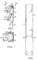
- a guide tube 4 is screwed to the rectilinear upper end of the neck tube 1 opposite the holding head 3 via an adapter piece (not shown in detail), on the outside of which a stop nut 5 is provided.
- a drive arrangement 6 is displaceable on the guide tube 4 between two end positions, see in particular FIG. 2.
- the drive arrangement 6 contains an outer sleeve 7 which is placed on the guide tube 4 and slides telescopically thereon. At the upper end, the outer sleeve 7 is connected to a clamping piece 8, which serves to receive the actual drive (not shown in the figures) and to attach a handle 9.
- a drive shaft 10, which is located in Extends longitudinally through the screwing device and at the lower end of which a drive tool 11 is attached. It can be a standard screwdriver bit.
- the displaceability of the drive arrangement 6 is limited by stops, the lower position being able to be finely adjusted by the abovementioned stop nut 5 shown in FIG. 1.
- a charging housing 12 is fastened in its upper region to the inlet connection 2 forming the branch.
- the feed housing 12 contains a downward-facing passage 13, which is arranged in the extension of the inlet connector 2 and through which a fastening element, for example a screw, can fall to the holding head 3.
- a magazine 14 is fastened to the side of the loading housing 12 and essentially consists of two magazine plates which run parallel to one another and form an intermediate space between them. These magazine plates can be flat, so that they extend laterally, or they can also be curved so that the magazine 14 as a whole extends around the device.
- the two plates forming the magazine 14 have an upper edge 15 which run obliquely downwards in the direction of the passage 13 of the loading housing 12.
- a separating device 16 is arranged on the end of the magazine 14 facing the loading housing 12 and has a blocking element 17 which can be pivoted about a horizontal axis.
- the locking element has two lugs 18, 19, of which the lug 18 closer to the passage 13 can be seen in FIG. 1.
- a prestressing sleeve 20 surrounding the drive shaft 10 is fastened within the guide tube 4 and has an outer shoulder 21 in the region of its end face facing the drive.
- An indicated compression spring 22 is supported on this shoulder, the other end of which rests on the drive. The strength of the Spring 22 is selected so that the drive is moved by this spring in the upper end position, which is shown in Fig. 1.
- the screw-in device described so far is operated as follows.
- the user places the device on the corresponding surface at a point where he wants to screw in a screw.
- a fastening element for example a screw
- a fastening element is dropped down through the passage 13 of the feed housing 12, arrives there in the holding head 3 and is held there by the holding elements to be described at two spaced-apart locations.
- the user uses the handle 9 to press the drive device 6 down until the tool 11 engages in the recess of the screw head. If he now presses the handle 9 further down, the holding elements and / or the impact of the tip of the screw on the surface creates a counterpressure which leads to the engagement of a clutch arranged in the drive.
- the tool 11 which has engaged in the recess of the screw head, is rotated and screwed in the screw. After this is screwed in, which the user can determine by the outer sleeve 7 resting on the stop nut 5, the user interrupts the feed movement and allows the drive to return to the starting position under the influence of the spring 22. Then a new fastener can fall into the holding head 3.
- Fig. 3 shows a longitudinal section through a jaw holder 23 for holding two clamping jaws 24, 25.
- the holding head 3 of Fig. 1 contains two such jaw holders 23 arranged symmetrically to the longitudinal axis of the device and to the longitudinal axis of the screw to be fastened.
- Fig. 4 shows a section approximately along line IV-IV in Fig. 3 through the jaw holder. This is designed as an approximately U-shaped profile, the two legs 26 of which are provided with fastening holes 27 for fastening to the neck tube 1 are. Shafts 28 extend between the legs 26 and serve as axes for the two clamping jaws 24, 25.
- Both clamping jaws are of similar design and contain a lower section in which a short channel-like clamping section 29 is formed. Above the clamping sections 29, the sides 30 of the clamping jaws 24, 25 directed towards the radial inside expand in a funnel-like manner.
- the lower clamping jaw 25 has a projection 31 in the region of its upper end, with which it engages on the inside of the clamping section 29 of the upper jaw 24. If the lower jaw 25 is pivoted clockwise into its closed position shown in FIG. 3, the projection 31 pushes the upper jaw 24 counterclockwise by a small amount, so that this jaw 24 is not in the fully closed position.
- a fastening element falling from top to bottom for example a screw, falls freely past the upper clamping jaws 24 until its tip is held on the clamping point 29 of the lower jaw.
- the fastener is always aligned at its tip, so that the distance of the tip of the fastener from the underside of the neck tube 1 is always the same and thus the screwing-in path is always the same.
- leaf springs 32 are used, which are inserted between the inside of the jaw holder 23 and the outside 33 of the jaws. They can be welded to the jaw holder, for example, on one leg.
- FIG. 4 shows the upper jaw 24 in supervision. It can be seen that a funnel 30 is actually formed here, if one takes into account that an identical arrangement is applied in mirror image from the other side.
- the mutual alignment between the jaw holder 23 and the neck tube 1 also results from FIG. 4, which shows the neck tube 1 schematically indicates correct positioning.
- the closed position of the two jaws is defined by the fact that the end faces 34 of the jaws lying in one diameter abut one another.
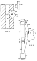
- FIG. 5 shows on the same scale as Figs. 3 and 4, a longitudinal section through the neck tube 1 with the insertion tube removed.
- the neck tube 1 has a rectangular or square cross section and contains an opening 35 on the side for inserting the insertion socket 2 and an opening 36 for the two jaw holders 23 in the lower region.
- FIG. 5 shows the holes 27 corresponding to the holes 27 in the side walls of the neck tube Holes 37.
- Fig. 6 shows a longitudinal section through the insertion nozzle 2, the function of which can be seen from Fig. 1.
- the insertion piece is inserted through the mentioned opening 35 into the neck tube and screwed there.
- a shoulder 38 is formed on the insertion nozzle 2, to which the connecting strap 39 shown in FIG. 10 can be screwed.
- the connecting tab 39 not only has holes for screwing onto the attachment 38, but also for screwing onto the loading housing 12 of FIG. 8. The further holes of the connecting tab 39 serve to screw the magazine 14 in place.
- an oval opening 40 is formed on the side next to the passage 13 in the upper region, in which the locking element 17, see FIG. 11, can be used.
- the locking element 17 has two lugs 18, 19 which are at a distance from one another which essentially corresponds to the diameter of a fastening element, for example a screw. One of the two lugs engages behind the last fastening element and the other behind the penultimate fastening element, as will be shown below.
- Fig. 9 shows a view of the loading housing of Fig. 8 from the right. It can be seen here that a recess 41 is formed on both sides for the connecting strap 39.
- the feed housing 12 includes a longitudinally extending slot 42, the width of which is slightly larger than a fastener. On both sides of the slot 12 holes 47 are arranged in the side edge 43 of the feed housing. One of these holes 44 serves to receive an axis about which the locking element 17 can pivot.
- Fig. 7 shows the top view of the insertion nozzle, it can be seen again that the insertion nozzle is attached to a neck tube which is rectangular in cross section.
- the locking element 17 is arranged to be pivotable about an axis passing through a hole 44.
- the locking element has two stable end positions, of which FIG. 12 represents one. In this end position, a nose 18 engages in the slot 42 of the loading housing. A fastening element lying in front of the nose 18 is prevented by the nose 18 from sliding into the passage 3 of the feed housing 12. If the device is now operated by screwing in a screw, a pin 46 attached to an actuating plate 45 comes to rest against a cam surface 47 of the locking element 17. When it is in contact and pushed further, the pin 46 pivots the locking element clockwise by an angle of approximately 45 °, so that the nose 18 is moved out of the slot 42.
- Fig. 13 shows the arrangement of the pin 46 at the lower end of the actuating plate 45, which in turn is fixed to a clamp 48 on the outer sleeve 7. A fine adjustment can be done with the help of a longitudinal slot 49. The next fastener is always released when it moves upwards, since the fastener then has sufficient time to fall to the holding head.
- the effect of the stop nut 5, which limits the downward displacement of the outer sleeve 7, can be seen again from FIG. 13.
- the stop nut 5 can be adjusted very finely due to its threaded connection with the neck tube 1 or the guide tube 4, so that there is a precise stop.
- a stop can be attached to the holding head 3, in order, if necessary, to adjust the distance between the underside 49 of the neck tube 1 and the surface on which screwing is to be carried out.
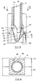
- the screwing device shown in FIGS. 14 and 15 contains, in the region of the lower end of its neck tube 1, a holding head 3 which is intended for holding the fastening elements, in particular screws.
- the neck tube 1 has an inner opening 50 with a circular cross section, see also FIG. 15.
- the holding head 3 is fastened to the outside of the neck tube 1. It can consist, for example, of two parts 3a, 3b which are divided along a central plane and which can be screwed together.
- the holding head 3 contains a widened inner opening 51 in which two holding jaws 52 can be pivoted are stored.
- the two holding jaws 52 are mirror-symmetrical to a longitudinal center plane and rest in the closed position shown in FIG.
- Both holding jaws 52 are pivotally articulated in the region of their upper end on laterally directed pins 54. They are acted upon in the illustrated closed position by means of springs 55 which are wound with their middle part around pins 56 and are supported with their two free ends, with one end on the wall of the holding head 3 and the other end on the outside of the holding jaw 52.
- a pin 57 is arranged in the region of the side walls of the holding head 3, which forms a central stop for both holding jaws 52.
- the inner walls 58 of the holding jaws run in a funnel shape, the funnel narrowing downward.
- the holding jaws 52 leave an opening 59 which is axially aligned. A screw coming down comes into this opening 59 with its tip and thereby centers itself.
- the lower edge 60 of the neck tube 1 extends somewhat lower than the top edge of the holding jaws 52, so that the neck tube and in particular its inner opening extends into the area between the two jaws 52.
- a screw falling from above through the neck tube 1 is held with its tip through the opening 59 between the two holding jaws 52.
- the head of the fastening element for example a countersunk head of a screw
- the wall of the neck tube 1 surrounding it A possible deviation of the longitudinal axis of the screw from the longitudinal axis of the device is caused by the Difference in diameter determined between the inner opening of the neck tube and the screw head.
- the invention provides for a further tubular element 61 to be inserted into the neck tube 1. In this way, screws with smaller head diameters can also be held. With the holding jaws 52 fully extended, the tubular element 61 can be removed downward from the holding head. In the same way it can also be inserted from below.
- FIG. 15 shows the arrangement of the tubular element 61 in the inner bore of the neck tube 1.
- a locking element 62 is indicated, which engages, for example under spring tension, in a recess in the tubular element 61 in order to hold it in the correct position.
- the additional tubular element 61 extends somewhat into the holding jaws 52 for the narrower screws.
- the holding head is particularly simple. It can not only be manufactured economically, but is particularly well suited for rough assembly operations due to its simple and robust construction.
Landscapes
- Engineering & Computer Science (AREA)
- Mechanical Engineering (AREA)
- Chemical & Material Sciences (AREA)
- Combustion & Propulsion (AREA)
- Details Of Spanners, Wrenches, And Screw Drivers And Accessories (AREA)
- Window Of Vehicle (AREA)
- Measuring Pulse, Heart Rate, Blood Pressure Or Blood Flow (AREA)
- Paper (AREA)
- Clamps And Clips (AREA)
Abstract
Description
Die Erfindung betrifft ein Verschraubungsgerät.The invention relates to a screwing device.
Es sind bereits Verschraubungsgeräte bekannt. Sie enthalten einen motorischen Antrieb, mit dem eine Schraube angetrieben und eingeschraubt werden kann. Die Schrauben werden durch ein Zuführrohr eingeworfen und fallen bis zu einem Haltekopf, der im unteren Bereich des Gerätes angeordnet ist. Dort werden die Schrauben gehalten. Der Benutzer drückt den Antrieb nach unten, bis dieser mit einem Werkzeug in den Schraubenkopf eingreift und die Schraube eindreht.Screwing devices are already known. They contain a motor drive with which a screw can be driven and screwed in. The screws are inserted through a feed tube and fall to a holding head, which is arranged in the lower area of the device. The screws are held there. The user presses the drive down until it engages the screw head with a tool and screws in the screw.
Bei einem bekannten Gerät (DE-A1-26 24 441) wird die Schraube von zwei an der gleichen axialen Stelle angeordneten Halteelementen gehalten, die zwischen sich einen zylindrischen Durchgang bilden. Da es sich bei den einzuschraubenden Schrauben im Normalfall um Schrauben mit einem Bohrkopf und sich daran anschließenden seitlichen Flügeln handelt, können mit einem solchen Gerät nur Schrauben verarbeitet werden, bei denen der Abstand zwischen dem Schraubenkopf und den Flügeln größer ist als die Länge der Halteelemente. Die Halteelemente greifen so an, daß die Schraube mit ihrem Kopf an der Oberseite der Halteelemente hängen bleibt. Dies bedeutet, daß eine Ausrichtung nach dem Kopf der Schraube erfolgt.In a known device (DE-A1-26 24 441), the screw is held by two holding elements arranged at the same axial position, which form a cylindrical passage between them. Since the screws to be screwed in are normally screws with a drill head and adjoining side wings, only screws can be processed with such a device in which the distance between the screw head and the wings is greater than the length of the holding elements. The holding elements grip like this that the screw gets stuck on the top of the holding elements. This means that it is aligned with the head of the screw.
Ebenfalls bekannt ist ein solches Gerät, bei dem zum Halten der Schraube zwei unter Federdruck radial nach innen beaufschlagte Kugeln vorhanden sind. Diese greifen ebenfalls an der Schraube unterhalb des Kopfes an. Auf diese Weise können zwar recht kurze Schrauben auch gehaltert werden, jedoch erfolgt wiederum eine Ausrichtung nach dem Kopf der Schraube. Zusätzlich tritt der Nachteil hinzu, daß die Schraube in Axialrichtung schlecht geführt ist.Such a device is also known, in which two balls are present which are acted upon radially inwards under spring pressure in order to hold the screw. These also attack the screw below the head. In this way, quite short screws can also be held, but in turn they are aligned to the head of the screw. In addition, there is the disadvantage that the screw is poorly guided in the axial direction.
Der Erfindung liegt die Aufgabe zugrunde, ein leicht handhabbares Gerät zum Eintreiben eines Befestigungselementes zu schaffen, bei dem nur eine kurze Eintreibbewegung erforderlich ist und bei dem dennoch Befestigungselemente eines sehr großen Bereiches an Abmessungen ohne Änderung verwendet werden können.The invention has for its object to provide an easy-to-use device for driving a fastener in which only a short driving movement is required and in which fasteners of a very wide range of dimensions can still be used without change.
Zur Lösung dieser Aufgabe schlägt die Erfindung ein Gerät mit den Merkmalen des Anspruchs 1 vor. Weiterbildungen sind Gegenstand der Unteransprüche.To achieve this object, the invention proposes a device with the features of
Durch die Halterung des Befestigungselementes an zwei Stellen, die voneinander einen Abstand aufweisen, wird eine bessere Halterung des Befestigungselementes und eine bessere Führung in Längsrichtung ermöglicht. Das Befestigungselement bleibt auch dann ausgerichtet, wenn der Antrieb einsetzt, das Befestigungselement aber in dem zu befestigenden Teil noch nicht geführt ist.By holding the fastening element at two locations that are spaced apart from one another, better fastening of the fastening element and better guidance in the longitudinal direction is made possible. The fastening element remains aligned even when the drive starts, but the fastening element is not yet guided in the part to be fastened.
In Weiterbildung der Erfindung kann vorgesehen sein, daß das Befestigungselement im Bereich seines vorderen Endes ausgerichtet wird. Das vordere Ende ist dasjenige Ende des Befestigungselementes, das zuerst in das Teil, in das es eingetrieben werden soll, eingreift. Bei einer Schraube ist das vordere Ende also das mit der Schraubenspitze versehen Ende. Auf diese Weise kann selbst bei Befestigungselementen sehr unterschiedlicher Länge immer dafür gesorgt werden, daß die Spitze in einem bestimmten geringen Abstand vor der Oberfläche gehaltert wird, in die das Befestigungselement eingetrieben werden soll. Dies bedeutet, daß der Eintreibweg immer möglichst kurz ist.In a further development of the invention it can be provided that the fastening element is aligned in the region of its front end. The front end is the end of the fastener that first engages the part into which it is to be driven. So the front end of a screw is the end with the screw tip. In this way, even with fasteners of very different lengths, it can always be ensured that the tip is held at a certain short distance from the surface into which the fastener is to be driven. This means that the drive-in distance is always as short as possible.
Die von der Erfindung vorgeschlagene Möglichkeit, das Befestigungselement sowohl an seinem Kopf als auch an seiner Spitze zu haltern, ist besonders vorteilhaft, da auf diese Weise der größtmögliche Abstand zwischen den zwei Stellen geschaffen wird, an denen das Befestigungselement festgehalten wird.The possibility proposed by the invention of holding the fastening element both at its head and at its tip is particularly advantageous since in this way the greatest possible distance is created between the two locations at which the fastening element is held.
In Weiterbildung kann vorgesehen sein, daß zum Angreifen an der Spitze des Befestigungselements mindestens ein, vorzugsweise zwei seitlich bewegbare Haltebacken vorgesehen sind, die insbesondere verschwenkbar ausgebildet sind.In a further development it can be provided that at least one, preferably two, laterally movable holding jaws are provided for gripping the tip of the fastening element, which are in particular designed to be pivotable.
Es kann erfindungsgemäß vorgesehen sein, daß die Haltebacken in geschlossenem Zustand zwischeneinander eine Öffnung frei lassen, die axial gegenüber dem Gerät ausgerichtet sein kann und in der die Spitze des Befestigungselements gehalten wird. Das Befestigungselement kann sich also zwischen den beiden Haltebacken selbst zentrieren, so daß bei entsprechender Ausbildung die Haltebacken auch keine Klemmwirkung aufzuweisen brauchen.It can be provided according to the invention that in the closed state the holding jaws leave an opening between them which can be aligned axially with respect to the device and in which the tip of the fastening element is held. The fastening element can thus center itself between the two holding jaws, so that the holding jaws need not have any clamping action if the appropriate design is used.
Zur Halterung des Befestigungselementes im Bereich seines Kopfes kann erfindungsgemäß vorgesehen sein, daß die Halterung ein Rohrelement aufweist, das das Befestigungselement und insbesondere dessen Kopf umgibt. Aufgrund der Halterung an zwei voneinander entfernten Stellen wird es möglich, die Halterung des Befestigungselementes in dem Kopfbereich nur annähernd durchzuführen, so daß hier ein gewisser radialer Abstand vorhanden sein kann. Das Rohrelement kann beispielsweise einen kreisrunden Innenquerschnitt aufweisen, der größer als die maximale Querabmessung des Kopfes des Befestigungselements ist.To hold the fastening element in the region of its head, it can be provided according to the invention that the holder has a tubular element which surrounds the fastening element and in particular its head. Because of the mounting at two points apart from one another, it becomes possible to carry out the mounting of the fastening element in the head region only approximately, so that there can be a certain radial distance here. The tubular element can, for example, have a circular inner cross section which is larger than the maximum transverse dimension of the head of the fastening element.
Bei einem bestimmten Innendurchmesser des Rohrelementes können durchaus Befestigungselemente unterschiedlicher Querabmessungen verwendet werden. Ggf. kann auch vorgesehen sein, wenn Befestigungselemente stark unterschiedlicher Abmessungen verwendet werden sollen, das Rohrelement auszutauschen. Hierunter ist auch zu verstehen, daß in eine rohrförmige Ausbildung der Halterung ein zweites Rohrelement eingesetzt wird. Insbesondere kann vorgesehen sein, daß das Rohrelement von der Unterseite des Gerätes her einsetzbar und/oder herausnehmbar ist. Auf diese Weise läßt sich die Umrüstung für ein anderes Befestigungselement sehr einfach und sehr schnell durchführen.With a certain inner diameter of the tubular element, fastening elements of different transverse dimensions can certainly be used. Possibly. can also be provided if fastening elements of very different dimensions are to be used to replace the tubular element. This also means that a second tubular element is inserted into a tubular configuration of the holder. In particular, it can be provided that the tubular element can be inserted and / or removed from the underside of the device. In this way, the conversion for another fastener can be carried out very easily and very quickly.
Damit das einsetzbare oder austauschbare Rohrelement immer richtig positioniert ist, kann erfindungsgemäß vorgesehen sein, das Rohrelement rastend zu haltern. Beispielsweise können unter Federbelastung stehende Kugeln vorgesehen sein, die in entsprechende Vertiefungen des Rohrelements eingreifen.So that the insertable or interchangeable tubular element is always correctly positioned, it can be provided according to the invention to hold the tubular element in a latching manner. For example, balls under spring loading can be provided which engage in corresponding recesses in the tubular element.
Erfindungsgemäß kann vorgesehen sein, daß das Rohrelement von oben her zwischen die Haltebacken eingreift.According to the invention it can be provided that the tubular element engages from above between the holding jaws.
Erfindungsgemäß kann vorgesehen sein, daß die Halterung mindestens zwei Klemmelemente aufweist, die gegen das Befestigungselement in eine geschlossene Stellung beaufschlagt und mindestens teilweise unabhängig voneinander bewegbar sind. Die Möglichkeit, beide Klemmelemente mindestens in einem bestimmten Bereich unabhängig voneinander zu bewegen, macht die Verwendung auch bei komplizierten Formen der Befestigungselemente möglich, beispielsweise bei den oben erwähnten, mit Flügeln versehenen Schrauben.According to the invention it can be provided that the holder has at least two clamping elements which act against the fastening element in a closed position and are at least partially movable independently of one another. The possibility of moving both clamping elements independently of one another in at least a certain area makes use possible even with complicated shapes of the fastening elements, for example with the above-mentioned, winged screws.
Erfindungsgemäß kann in Weiterbildung vorgesehen sein, daß die Klemmelemente derart geführt sind, daß dann, wenn das Klemmelement für die Spitze des Befestigungselementes geschlossen ist, das andere Klemmelement mindestens teilweise geöffnet ist. Da die Befestigungselemente durch die Zuführeinrichtung im Normalfall nach unten bewegt werden, also herabfallen, wird auf diese Weise dafür gesorgt, daß die Spitze des Befestigungselementes durch die Stelle des etwas geöffneten oberen Klemmelementes hindurchfällt und erst vom unteren Klemmelement festgehalten wird. Das gleiche gilt natürlich auch, wenn in anderer Richtung gearbeitet wird.According to the invention, it can be provided in a further development that the clamping elements are guided such that when the clamping element for the tip of the fastening element is closed, the other clamping element is at least partially open. There the fasteners are moved downwards by the feed device in the normal case, that is, they fall down, in this way it is ensured that the tip of the fastener falls through the location of the slightly open upper clamping element and is only held by the lower clamping element. The same applies, of course, when working in a different direction.
In Weiterbildung kann erfindungsgemäß vorgesehen sein, die gegenseitige Beeinflussung der beiden Klemmelemente so auszugestalten, daß dann, wenn das Klemmelement für die Spitze des Befestigungselementes in nichtgeschlossener Stellung ist, das andere Klemmelement im ersten Klemmelement unbeeinflußt ist. Hiermit wird das Durchschieben komplizierterer Formen von Klemmelementen erleichtert. Das zweite Klemmelement kann auf diese Weise beispielsweise nach dem Hindurchbewegen der Flügel wieder an den Schaft einer Schraube heranschwenken.In a further development it can be provided according to the invention to design the mutual influence of the two clamping elements so that when the clamping element for the tip of the fastening element is in the non-closed position, the other clamping element in the first clamping element is unaffected. This makes it easier to push through more complicated shapes of clamping elements. In this way, the second clamping element can pivot back to the shaft of a screw, for example after the wings have been moved through.
Insbesondere kann vorgesehen sein, daß im Bereich zwischen den Klemmstellen ein radialer Abstand zwischen dem Befestigungselement und der Halteeinrichtung vorgesehen ist.In particular, it can be provided that a radial distance between the fastening element and the holding device is provided in the area between the clamping points.
Erfindungsgemäß kann vorgesehen sein, daß sich die beiden Klemmeinrichtungen beim Eintreiben des Befestigungselementes nacheinander öffnen.According to the invention it can be provided that the two clamping devices open one after the other when driving in the fastening element.
Die Erfindung schlägt vor, daß mindestens eine Klemmeinrichtung von mindestens einer Klemmbacke gebildet werden kann, die sich im wesentlichen radial bewegt.The invention proposes that at least one clamping device can be formed by at least one clamping jaw, which moves essentially radially.
Besonders günstig ist es, wenn für eine Klemmstelle zwei symmetrisch zur Längsachse des Befestigungselementes angeordnete Klemmbacken vorhanden sind.It is particularly favorable if there are two clamping jaws arranged symmetrically to the longitudinal axis of the fastening element for a clamping point.
Die Klemmelemente der Halterung können mit Vorteil durch Federn beaufschlagt sein.The clamping elements of the holder can advantageously be acted upon by springs.
In Weiterbildung der Erfindung kann vorgesehen sein, daß die Zuführeinrichtung zum Zuführen der Befestigungselemente ein Magazin für diese aufweist. Dadurch wird es dem Benutzer ermöglicht, beispielsweise eine ganze Reihe von Brettern am Boden anzuschrauben, ohne jeweils zwischen den Schraubvorgängen das Gerät absetzen und ein Befestigungselement nachschieben zu müssen. Insbesondere kann vorgesehen sein, daß das Magazin derart ausgebildet ist, daß es die Befestigungselemente lose aufnimmt.In a further development of the invention, it can be provided that the feed device for feeding the fastening elements has a magazine for them. This enables the user, for example, to screw a whole row of boards onto the floor without having to put the device down between the screwing operations and without having to push in a fastening element. In particular, it can be provided that the magazine is designed such that it loosely receives the fastening elements.
Die Erfindung sieht vor, daß das Magazin bzw. die Zuführeinrichtung eine Vereinzelungseinrichtung für die Befestigungselemente aufweist, die beim Eintreiben des Befestigungselementes weitergeschaltet wird. Dies kann vorteilhafterweise in einem zweistufigen Vorgang geschehen. Beim Vorteiben des Antriebs wird die vorderste Schraube von den anderen getrennt, und beim Zurückziehen des Antriebs freigegeben, so daß sie durch die Zuführeinrichtung zum Haltekopf fällt.The invention provides that the magazine or the feed device has a separating device for the fastening elements, which is switched on when the fastening element is driven in. This can advantageously be done in a two-stage process. When the drive is advanced, the foremost screw is separated from the others and released when the drive is pulled back so that it falls through the feed device to the holding head.
Erfindungsgemäß kann vorgesehen sein, daß die Zuführeinrichtung eine Möglichkeit zum Eingeben eines einzelnen Befestigungselementes unter Umgehung des Magazins aufweist.According to the invention, it can be provided that the feed device has the possibility of entering a single fastening element bypassing the magazine.
Besonders günstig ist das von der Erfindung vorgeschlagene Gerät zum Einschrauben von Schrauben geeignet. In diesem Fall kann vorgesehen sein, daß der Antrieb einen Schrauberantrieb mit einer durch den beim Einschrauben der Schraube entstehenden Gegendruck einrückbaren Kupplung aufweist. Der Motor dieses Schrauberantriebs läuft also ständig, während das von ihm angetriebene Werkzeug nur unter Gegendruck angetrieben wird. Dies macht das Eindringen des Werkzeugs in die Schraubenkopfausnehmung erst in vernünftiger Weise möglich.The device proposed by the invention is particularly suitable for screwing in screws. In this case it can be provided that the drive has a screwdriver drive with a clutch which can be engaged by the counterpressure generated when the screw is screwed in. The motor of this screwdriver drive runs constantly, while the tool it drives is only driven under counter pressure. This only makes it possible for the tool to penetrate the screw head recess in a reasonable manner.
Weitere Merkmale, Einzelheiten und Vorzüge der Erfindung ergeben sich aus den Patentansprüchen, deren Wortlaut durch Bezugnahme zum Inhalt der Beschreibung gemacht wird, der folgenden Beschreibung bevorzugter Ausführungsformen der Erfindung sowie anhand der Zeichnung. Hierbei zeigen, jeweils vereinfacht:
- Fig. 1
- eine teilweise geschnittene Seitenansicht des unteren Teils eines Einschraubgeräts nach der Erfindung;
- Fig. 2
- den oberen Teil des Gerätes;
- Fig. 3
- einen Schnitt durch zwei Klemmbacken des Haltekopfs;
- Fig. 4
- einen Querschnitt durch den Haltekopf;
- Fig. 5
- einen Längsschnitt durch das Halsrohr des Verschraubungsgerätes;
- Fig. 6
- einen Schnitt durch einen Einführstutzen für das Halsrohr;
- Fig. 7
- die Aufsicht auf den Einführstutzen der Fig. 6;
- Fig. 8
- einen Schnitt durch das Beschickungsgehäuse eines Magazins;
- Fig. 9
- die Seitenansicht des Beschickungsgehäuses von der Seite her, an der das Magazin angebracht wird;
- Fig. 10
- eine Verbindungslasche zum Verbinden des Beschickungsgehäuses mit dem Einführstutzen und dem Magazin;
- Fig. 11
- die Seitenansicht einer Sperrklinke einer Vereinzelungseinrichtung;
- Fig. 12
- in vergrößertem Maßstab einen Schnitt durch das Beschickungsgehäuse;
- Fig. 13
- schematisch die Möglichkeit der Betätigung der Vereinzelungseinrichtung.
- Fig. 14
- schematisch eine teilweise geschnittene Ansicht des Haltekopfs des Verschraubungsgerätes;
- Fig. 15
- ein vergrößerten Schnitt etwa längs Linie II-II in Fig. 14
- Fig. 1
- a partially sectioned side view of the lower part of a screwing device according to the invention;
- Fig. 2
- the upper part of the device;
- Fig. 3
- a section through two jaws of the holding head;
- Fig. 4
- a cross section through the holding head;
- Fig. 5
- a longitudinal section through the neck tube of the screwing device;
- Fig. 6
- a section through an insertion for the neck tube;
- Fig. 7
- the supervision of the introducer of Fig. 6;
- Fig. 8
- a section through the feed housing of a magazine;
- Fig. 9
- the side view of the feed housing from the side on which the magazine is attached;
- Fig. 10
- a connecting strap for connecting the feeder housing to the insertion nozzle and the magazine;
- Fig. 11
- the side view of a pawl of a separating device;
- Fig. 12
- on a larger scale, a section through the loading housing;
- Fig. 13
- schematically the possibility of actuating the separating device.
- Fig. 14
- schematically shows a partially sectioned view of the holding head of the screwing device;
- Fig. 15
- an enlarged section along the line II-II in Fig. 14th
An dem dem Haltekopf 3 entgegengesetzten geradlinigen oberen Ende des Halsrohres 1 ist über ein im einzelnen nicht dargestelltes Adapterstück ein Führungsrohr 4 angeschraubt, an dessen Außenseite eine Anschlagmutter 5 vorgesehen ist. Auf dem Führungsrohr 4 verschiebbar zwischen zwei Endstellungen ist eine Antriebsanordnung 6, siehe insbesondere Fig. 2. Die Antriebsanordnung 6 enthält eine Außenhülse 7, die auf dem Führungsrohr 4 aufgesetzt ist und auf diesem teleskopartig gleitet. Am oberen Ende ist die Außenhülse 7 mit einem Klemmstück 8 verbunden, das zur Aufnahme des eigentlichen, in den Figuren nicht dargestellten Antriebs sowie zur Anbringung eines Handgriffs 9 dient. Mit dem Antrieb verbunden ist eine Antriebswelle 10, die sich in Längsrichtung durch das Verschraubungsgerät erstreckt und an deren unterem Ende ein Antriebswerkzeug 11 angebracht ist. Es kann sich dabei um einen üblichen Schraubendreherbit handeln. Die Verschiebbarkeit der Antriebsanordnung 6 ist durch Anschläge begrenzt, wobei die untere Stellung durch die bereits erwähnte, in Fig. 1 dargestellte Anschlagmutter 5 fein eingestellt werden kann.A
An dem die Abzweigung bildenden Einführstutzen 2 ist in seinem oberen Bereich ein Beschickungsgehäuse 12 befestigt. Das Beschickungsgehäuse 12 enthält einen nach unten gerichteten, in Verlängerung des Einführstutzens 2 angeordneten Durchgang 13, durch den ein Befestigungselement, beispielsweise eine Schraube, zum Haltekopf 3 fallen kann. An dem Beschickungsgehäuse 12 ist seitlich ein Magazin 14 befestigt, das im wesentlichen aus zwei parallel zueinander verlaufenden und einen Zwischenraum zwischen sich bildenden Magazinplatten besteht. Diese Magazinplatten können eben ausgebildet sein, so daß sie sich also seitlich erstrecken, oder aber auch gebogen, so daß das Magazin 14 insgesamt sich um das Gerät herum erstreckt. Die beiden das Magazin 14 bildenden Platten weisen eine Oberkante 15 auf, die in Richtung auf den Durchgang 13 des Beschickungsgehäuses 12 schräg abwärts verlaufen. Dadurch entsteht eine Kraftkomponente, die in dem Magazin 14 enthaltene Befestigungselemente in Richtung auf die Zuführeinrichtung beaufschlagt. An dem dem Beschickungsgehäuse 12 zugewandten Ende des Magazins 14 ist eine Vereinzelungseinrichtung 16 angeordnet, die ein um eine horizontale Achse verschwenkbares Sperrelement 17 aufweist. Das Sperrelement weist zwei Nasen 18, 19 auf, von denen in Fig. 1 die näher an dem Durchgang 13 liegende Nase 18 zu sehen ist.A charging
Innerhalb des Führungsrohres 4 ist eine die Antriebswelle 10 umgebende Vorspannhülse 20 befestigt, die im Bereich ihrer dem Antrieb zugewandten Stirnseite eine äußere Schulter 21 aufweist. Auf dieser Schulter stützt sich eine angedeutete Druckfeder 22 ab, deren anderes Ende an dem Antrieb anliegt. Die Stärke der Feder 22 ist so gewählt, daß der Antrieb von dieser Feder in die obere Endposition verschoben wird, die in der Fig. 1 dargestellt ist.A
Das insoweit beschriebene Einschraubgerät wird folgendermaßen bedient. Der Benutzer setzt das Gerät an einer Stelle, an der er eine Schraube eindrehen will, auf der entsprechenden Oberfläche ab. Ein Befestigungselement, beispielsweise eine Schraube wird durch den Durchgang 13 des Beschickungsgehäuses 12 nach unten fallengelassen, gelangt dort in den Haltekopf 3 und wird dort von den noch zu beschreibenden Halteelementen an zwei beabstandeten Stellen festgehalten. Dann drückt der Benutzer mit Hilfe des Griffs 9 die Antriebseinrichtung 6 nach unten, bis das Werkzeug 11 in die Ausnehmung des Schraubenkopfes eingreift. Drückt er nun den Griff 9 weiter herunter, so entsteht durch die Halteelemente und/oder das Auftreffen der Spitze der Schraube auf der Oberfläche ein Gegendruck, der zu einem Einrücken einer in dem Antrieb angeordneten Kupplung führt. Jetzt wird das Werkzeug 11, das in der Ausnehmung des Schraubenkopfes eingegriffen hat, in Drehbewegung versetzt und schraubt die Schraube ein. Nachdem diese eingeschraubt ist, was der Benutzer durch Anliegen der Außenhülse 7 an der Anschlagmutter 5 feststellen kann, unterbricht der Benutzer die Vorschubbewegung und läßt den Antrieb unter dem Einfluß der Feder 22 in die Ausgangsstellung zurückkehren. Dann kann ein neues Befestigungselement in den Haltekopf 3 herabfallen.The screw-in device described so far is operated as follows. The user places the device on the corresponding surface at a point where he wants to screw in a screw. A fastening element, for example a screw, is dropped down through the
Einzelheiten des Haltekopfes sind in Fig. 3 und 4 dargestellt. Fig. 3 Zeigt einen Längsschnitt durch eine Backenhalterung 23 zur Halterung zweier Klemmbacken 24, 25. Der Haltekopf 3 der Fig. 1 enthält zwei symmetrisch zur Längsachse des Gerätes und zur Längsachse der zu befestigenden Schraube angeordnete derartige Backenhalterungen 23. Fig. 4 zeigt einen Schnitt etwa nach Linie IV-IV in Fig. 3 durch die Backenhalterung. Diese ist als etwa U-förmiges Profil ausgebildet, dessen beide Schenkel 26 mit Befestigungslöchern 27 zur Befestigung an dem Halsrohr 1 versehen sind. Zwischen den Schenkeln 26 erstrecken sich Wellen 28, die als Achse für die beiden Klemmbacken 24, 25 dienen. Beide Klemmbacken sind ähnlich ausgebildet und enthalten einen unteren Abschnitt, in dem ein kurzer rinnenartiger Klemmabschnitt 29 gebildet ist. Oberhalb der Klemmabschnitte 29 erweitern sich die zur radialen Innenseite gerichteten Seiten 30 der Klemmbacken 24, 25 trichterartig. Die untere Klemmbacke 25 weist im Bereich ihres oberen Endes einen Vorsprung 31 auf, mit dem sie an der Innenseite des Klemmabschnittes 29 der oberen Backe 24 angreift. Ist die untere Klemmbacke 25 in ihre in der Fig. 3 dargestellten geschlossenen Stellung im Uhrzeigersinn verschwenkt, so drückt der Vorsprung 31 die obere Klemmbacke 24 im Gegenuhrzeigersinn um einen kleinen Betrag, so daß diese Klemmbacke 24 nicht in der vollständig geschlossenen Stellung liegt. Dadurch wird erreicht, daß ein von oben nach unten fallendes Befestigungselement, beispielsweise eine Schraube, an dem oberen Klemmbacken 24 ungehindert vorbeifällt, bis ihre Spitze an der Klemmstelle 29 des unteren Backens festgehalten wird. Dadurch erfolgt eine Ausrichtung des Befestigungselementes immer an seiner Spitze, so daß der Abstand der Spitze des Befestigungselementes von der Unterseite des Halsrohres 1 immer gleich ist und somit auch der Einschraubweg immer gleich groß ist.Details of the holding head are shown in Figs. 3 and 4. Fig. 3 shows a longitudinal section through a
Zur Beaufschlagung der Backen 24, 25 in ihrer geschlossenen Stellung, entsprechend dem Uhrzeigersinn in Fig. 3, dienen Blattfedern 32, die zwischen die Innenseite der Backenhalterung 23 und die Außenseiten 33 der Backen eingesetzt werden. Sie können an der Backenhalterung beispielsweise an ihrem einen Schenkel angeschweißt werden.To act upon the
Der Schnitt der Fig. 4 zeigt den oberen Backen 24 in Aufsicht. Es ist dabei zu sehen, daß hier tatsächlich ein Trichter 30 gebildet ist, wenn man berücksichtigt, daß spiegelbildlich eine gleiche Anordnung von der anderen Seite angebracht wird. Die gegenseitige Ausrichtung zwischen der Backenhalterung 23 und dem Halsrohr 1 ergibt sich ebenfalls aus Fig. 4, die das Halsrohr 1 schematisch in richtiger Positionierung andeutet. Die geschlossene Stellung der beiden Backen wird dadurch definiert, daß die in einem Durchmesser liegenden Stirnseiten 34 der Backen aneinander anliegen.The section of FIG. 4 shows the
Fig. 5 zeigt in gleichem Maßstab wie Fig. 3 und 4 einen Längsschnitt durch das Halsrohr 1 mit abgenommenem Einführstutzen. Das Halsrohr 1 weist einen rechteckigen bzw. quadratischen Querschnitt auf und enthält seitlich eine Öffnung 35 zum Einsetzen des Einführstutzens 2 sowie im unteren Bereich je eine Öffnung 36 für die beiden Backenhalterungen 23. Fig. 5 zeigt in den Seitenwänden des Halsrohres die den Löchern 27 entsprechenden Löcher 37.Fig. 5 shows on the same scale as Figs. 3 and 4, a longitudinal section through the
Fig. 6 zeigt einen Längsschnitt durch den Einführstutzen 2, dessen Funktion aus Fig. 1 schon hervorgeht. Der Einführstutzen wird durch die erwähnte Öffnung 35 in das Halsrohr eingeschoben und dort festgeschraubt. An seiner dem Halsrohr 1 abgewandten Seite ist ein Ansatz 38 an dem Einführstutzen 2 ausgebildet, an dem die in Fig. 10 dargestellte Verbindungslasche 39 festgeschraubt werden kann. Die Verbindungslasche 39 weist nicht nur Löcher zum Anschrauben an dem Ansatz 38, sondern auch zum Anschrauben an dem Beschickungsgehäuse 12 der Fig. 8 auf. Die weiteren Löcher der Verbindungslasche 39 dienen zum Festschrauben des Magazins 14.Fig. 6 shows a longitudinal section through the
In dem Beschickungsgehäuse 12 ist seitlich neben dem Durchgang 13 im oberen Bereich eine ovale Öffnung 40 ausgebildet, in der das Sperrelement 17, siehe Fig. 11, eingesetzt werden kann. Das Sperrelement 17 weist zwei Nasen 18, 19 auf, die voneinander einen Abstand aufweisen, der im wesentlichen dem Durchmesser eines Befestigungselementes, beispielsweise also einer Schraube, entspricht. Eine der beiden Nasen greift dabei hinter dem letzten Befestigungselement, und die andere hinter dem vorletzten Befestigungselement an, wie dies im folgenden noch dargestellt werden wird.In the charging
Fig. 9 zeigt eine Ansicht des Beschickungsgehäuses der Fig. 8 von rechts. Es ist hier zu sehen, daß eine Ausnehmung 41 beidseits für die Verbindungslasche 39 gebildet ist. Das Beschickungsgehäuse 12 enthält einen sich in Längsrichtung erstreckenden Schlitz 42, dessen Breite etwas größer als ein Befestigungselement ist. Beidseits des Schlitzes sind in der Seitenkante 43 des Beschickungsgehäuses 12 Löcher 47 angeordnet. Eines dieser Löcher 44 dient zur Aufnahme einer Achse, um die sich das Sperrelement 17 verschwenken kann.Fig. 9 shows a view of the loading housing of Fig. 8 from the right. It can be seen here that a
Fig. 7 zeigt die Aufsicht auf den Einführstutzen, wobei wieder zu sehen ist, daß der Einführstutzen an einem im Querschnitt rechtwinkligen Halsrohr befestigt wird.Fig. 7 shows the top view of the insertion nozzle, it can be seen again that the insertion nozzle is attached to a neck tube which is rectangular in cross section.
Einzelheiten der Vereinzelungseinrichtung, die das Sperrelement 17 aufweist, sind aus Fig. 12 zu sehen. Das Sperrelement 17 ist um eine durch ein Loch 44 gehende Achse verschwenkbar angeordnet. Das Sperrelement weist zwei stabile Endstellungen auf, von denen Fig. 12 eine darstellt. In dieser Endstellung greift eine Nase 18 in den Schlitz 42 des Beschickungsgehäuses ein. Ein vor der Nase 18 liegendes Befestigungselement wird durch die Nase 18 daran gehindert, in den Durchgang 3 des Beschickungsgehäuses 12 zu rutschen. Wird nun das Gerät betrieben, indem eine Schraube eingeschraubt wird, so gelangt ein an einer Betätigungsplatte 45 angebrachter Zapfen 46 zur Anlage an einer Nockenfläche 47 des Sperrelements 17. Bei Anlage und Weiterschieben verschwenkt der Zapfen 46 das Sperrelement im Uhrzeigersinn um einen Winkel von etwa 45°, so daß die Nase 18 aus dem Schlitz 42 herausbewegt wird. Gleichzeitig wird aber die mit Abstand zur Nase 18 angeordnete Nase 19 in den Schlitz hineinbewegt. Wenn die Schraube eingeschraubt ist, so bewegt sich der Antrieb unter der Wirkung der Feder 22 wieder nach oben, und der Zapfen 46 gelangt nun zur Anlage an der zweiten Nockenfläche 48 des Sperrelementes 17 und verschwenkt dieses wieder in die Ausgangsstellung. Zu diesem Zeitpunkt kann das das unmittelbar vor dem Beschickungsgehäuse 12 vorhandene Befestigungselement in den Durchgang 13 gelangen und nach unten zum Haltekopf fallen. Zum Freigeben eines Befestigungselementes ist also eine hin- und hergehende Bewegung des Zapfens erforderlich. Zum Festlegen des Sperrelementes dient ein Kugeldruckstück, das in eine von zwei Vertiefungen eingreift.Details of the separating device which has the blocking
Fig. 13 zeigt die Anordnung des Zapfens 46 am unteren Ende der Betätigungsplatte 45, die ihrerseits an einer Schelle 48 an der Außenhülse 7 festgelegt ist. Eine Feinabstellung kann mit Hilfe eines Längsschlitzes 49 geschehen. Die Freigabe des jeweils nächsten Befestigungselementes geschieht immer bei er Aufwärtsbewegung, da dann das Befestigungselement ausreichend Zeit hat, zum Haltekopf zu fallen.Fig. 13 shows the arrangement of the
Aus Fig. 13 ist im übrigen nochmals die Wirkung der Anschlagmutter 5 zu sehen, die das Abwärtsverschieben der Außenhülse 7 begrenzt. Die Anschlagmutter 5 kann aufgrund ihrer Gewindeverbindung mit dem Halsrohr 1 oder dem Führungsrohr 4 sehr fein verstellt werden, so daß sich ein genauer Anschlag ergibt.The effect of the
An dem Haltekopf 3 kann im übrigen ein in der Figur nicht dargestellter Anschlag angebracht sein, um ggf. den Abstand zwischen der Unterseite 49 des Halsrohres 1 und der Oberfläche, auf der festgeschraubt werden soll, einzustellen.In addition, a stop, not shown in the figure, can be attached to the holding
Ählich wie bei dem oben beschriebenen Gerät enthält das in Fig. 14 und 15 dargestellte beschriebene Verschraubungsgerät im Bereich des unteren Endes seines Halsrohrs 1 einen Haltekopf 3, der zum Halten der Befestigungselemente, insbesondere von Schrauben, bestimmt ist. Das Halsrohr 1 weist eine Innenöffnung 50 mit kreisrundem Querschnitt auf, siehe auch Fig. 15. Der Haltekopf 3 ist an der Außenseite des Halsrohrs 1 befestigt. Er kann beispielsweise aus zwei Teilen 3a, 3b bestehen, die längs einer Mittelebene geteilt sind und die miteinander verschraubt werden können. Im unteren Bereich enthält der Haltekopf 3 eine verbreiterte Innenöffnung 51, in der zwei Haltebacken 52 schwenkbar gelagert sind. Die beiden Haltebacken 52 sind spiegelsymmetrisch zu einer Längsmittelebene ausgebildet und liegen im Bereich dieser Mittelebene in ihrer in Fig. 14 dargestellten geschlossenen Stellung mit ihren Seitenkanten 53 aneinander an. Beide Haltebacken 52 sind im Bereich ihres oberen Endes an seitlich nach außen gerichteten Zapfen 54 schwenkbar angelenkt. Sie werden in die dargestellte geschlossene Stellung mit Hilfe von Federn 55 beaufschlagt, die mit ihren Mittelteil um Zapfen 56 herumgewickelt sind und mit ihren beiden freien Enden sich abstützen, mit dem einen Ende an der Wand des Haltekopfs 3 und mit dem anderen Ende an der Außenseite des Haltebackens 52.Similar to the device described above, the screwing device shown in FIGS. 14 and 15 contains, in the region of the lower end of its
Damit die Haltebacken 52 in geschlossenem Zustand immer symmetrisch angeordnet sind, ist im Bereich der Seitenwände des Haltekopfs 3 je ein Zapfen 57 angeordnet, der einen Mittelanschlag für beide Haltebacken 52 bildet.So that the holding
Die Innenwände 58 der Haltebacken verlaufen trichterförmig, wobei der Trichter sich nach unten verengt. Im Bereich der Unterseite lassen die Haltebacken 52 eine Öffnung 59 frei, die axial ausgerichtet ist. Eine nach unten gelangende Schraube gerät mit ihrer Spitze in diese Öffnung 59 und zentriert sich dadurch selbst.The
Die Unterkante 60 des Halsrohrs 1 reicht etwas tiefer als die Oberkante der Haltebacken 52, so daß das Halsrohr und insbesondere seine Innenöffnung bis in den Bereich zwischen den beiden Backen 52 reicht.The
Eine von oben durch das Halsrohr 1 nach unten fallende Schraube wird mit ihrer Spitze durch die Öffnung 59 zwischen den beiden Haltebacken 52 gehalten. Im Bereich ihres oberen Endes wird der Kopf des Befestigungselementes, beispielsweise ein Senkkopf einer Schraube, von der ihn umgebenden Wand des Halsrohrs 1 gehalten. Eine noch mögliche Abweichung der Längsachse der Schraube von der Längsachse des Geräts wird durch den Durchmesserunterschied zwischen der Innenöffnung des Halsrohrs und dem Schraubenkopf bestimmt. Um auch für kleinere Schraubenköpfe eine ausreichende Halterung zu gewährleisten, ist erfindungsgemäß vorgesehen, in das Halsrohr 1 ein weiteres Rohrelement 61 einzuschieben. Auf diese Weise lassen sich Schrauben mit kleineren Kopfdurchmesser ebenfalls haltern. Bei vollständig auseinandergeklappten Haltebacken 52 läßt sich das Rohrelement 61 nach unten aus dem Haltekopf herausnehmen. In gleicher Weise läßt es sich ebenfalls von unten her einschieben.A screw falling from above through the
In dem Schnitt der Figur 15 ist die Anordnung des Rohrelementes 61 in der Innenbohrung des Halsrohrs 1 zu sehen. Angedeutet ist ein Rastelement 62, das beispielsweise unter Federspannung stehend in eine Vertiefung des Rohrelementes 61 eingreift, um dieses in der korrekten Stellung zu haltern.The section of FIG. 15 shows the arrangement of the
Wie aus Figur 1 ebenfalls zu entnehmen ist, reicht das zusätzliche Rohrelement 61 für die schmaleren Schrauben etwas in die Haltebacken 52 hinein.As can also be seen from FIG. 1, the additional
Bei dem von der Erfindung vorgeschlagenen Verschraubungsgerät ist der Haltekopf besonders einfach aufgebaut. Er läßt sich nicht nur wirtschaftlich herstellen, sondern ist aufgrund seines einfachen und robusten Aufbaus für den rauhen Montagebetrieb besonders gut geeignet.In the screwing device proposed by the invention, the holding head is particularly simple. It can not only be manufactured economically, but is particularly well suited for rough assembly operations due to its simple and robust construction.
Claims (20)
Applications Claiming Priority (4)
| Application Number | Priority Date | Filing Date | Title |
|---|---|---|---|
| DE4141961 | 1991-12-19 | ||
| DE4141961A DE4141961A1 (en) | 1991-12-19 | 1991-12-19 | Mechanical screwdriver structure |
| DE4212614 | 1992-04-15 | ||
| DE4212614A DE4212614A1 (en) | 1991-12-19 | 1992-04-15 | Screwing device |
Publications (2)
| Publication Number | Publication Date |
|---|---|
| EP0547638A1 true EP0547638A1 (en) | 1993-06-23 |
| EP0547638B1 EP0547638B1 (en) | 1997-11-19 |
Family
ID=25910274
Family Applications (1)
| Application Number | Title | Priority Date | Filing Date |
|---|---|---|---|
| EP92121652A Expired - Lifetime EP0547638B1 (en) | 1991-12-19 | 1992-12-19 | Screwing device |
Country Status (4)
| Country | Link |
|---|---|
| EP (1) | EP0547638B1 (en) |
| AT (1) | ATE160307T1 (en) |
| DE (2) | DE4212614A1 (en) |
| ES (1) | ES2109304T3 (en) |
Cited By (5)
| Publication number | Priority date | Publication date | Assignee | Title |
|---|---|---|---|---|
| WO1994015736A1 (en) * | 1993-01-07 | 1994-07-21 | Henrob Ltd. | Improved fastening tools |
| DE19506336A1 (en) * | 1995-02-23 | 1996-08-29 | Sfs Ind Holding Ag | Device for screwing in that can be attached to a drive unit |
| EP0729809A1 (en) * | 1995-02-28 | 1996-09-04 | Max Co., Ltd. | Attachment for nailing machine |
| AU689457B2 (en) * | 1993-01-07 | 1998-04-02 | Henrob Ltd | Improved fastening tools |
| US6945140B2 (en) | 2003-08-21 | 2005-09-20 | Black & Decker Inc. | Automatic screwfeeder |
Citations (6)
| Publication number | Priority date | Publication date | Assignee | Title |
|---|---|---|---|---|
| GB230189A (en) * | 1923-12-08 | 1925-03-09 | Frederick William Henning | Improvements in and relating to screwdrivers |
| US1839490A (en) * | 1928-12-04 | 1932-01-05 | Western Electric Co | Apparatus for distributing parts |
| US2314760A (en) * | 1941-05-08 | 1943-03-23 | Phillips Screw Co | Power screw driver |
| US3524484A (en) * | 1968-05-01 | 1970-08-18 | Illinois Tool Works | Adjustable nosepiece for power screwdriver |
| DE2624441A1 (en) * | 1975-06-17 | 1976-12-30 | Illinois Tool Works | POWERED PORTABLE FASTENER AND DRIVE TOOL |
| DE3815814A1 (en) * | 1988-05-09 | 1989-11-23 | Lorenz Stoeger | Feeding device on a tool |
Family Cites Families (3)
| Publication number | Priority date | Publication date | Assignee | Title |
|---|---|---|---|---|
| DE7627652U1 (en) * | 1976-09-03 | 1977-01-20 | Deutsche Vereinigte Schuhmaschinen Gmbh, 6000 Frankfurt | Chuck for a screwdriver |
| US4510826A (en) * | 1983-03-07 | 1985-04-16 | Guardian Fasteners And Closure Systems | Extension for a screwgun |
| SU1115894A1 (en) * | 1983-07-28 | 1984-09-30 | Подольский Ордена Ленина И Ордена Трудового Красного Знамени Механический Завод Им.М.И.Калинина | Screw driver with automatic feed of fasteners |
-
1992
- 1992-04-15 DE DE4212614A patent/DE4212614A1/en not_active Withdrawn
- 1992-12-19 ES ES92121652T patent/ES2109304T3/en not_active Expired - Lifetime
- 1992-12-19 AT AT92121652T patent/ATE160307T1/en not_active IP Right Cessation
- 1992-12-19 EP EP92121652A patent/EP0547638B1/en not_active Expired - Lifetime
- 1992-12-19 DE DE59209024T patent/DE59209024D1/en not_active Expired - Fee Related
Patent Citations (6)
| Publication number | Priority date | Publication date | Assignee | Title |
|---|---|---|---|---|
| GB230189A (en) * | 1923-12-08 | 1925-03-09 | Frederick William Henning | Improvements in and relating to screwdrivers |
| US1839490A (en) * | 1928-12-04 | 1932-01-05 | Western Electric Co | Apparatus for distributing parts |
| US2314760A (en) * | 1941-05-08 | 1943-03-23 | Phillips Screw Co | Power screw driver |
| US3524484A (en) * | 1968-05-01 | 1970-08-18 | Illinois Tool Works | Adjustable nosepiece for power screwdriver |
| DE2624441A1 (en) * | 1975-06-17 | 1976-12-30 | Illinois Tool Works | POWERED PORTABLE FASTENER AND DRIVE TOOL |
| DE3815814A1 (en) * | 1988-05-09 | 1989-11-23 | Lorenz Stoeger | Feeding device on a tool |
Cited By (8)
| Publication number | Priority date | Publication date | Assignee | Title |
|---|---|---|---|---|
| WO1994015736A1 (en) * | 1993-01-07 | 1994-07-21 | Henrob Ltd. | Improved fastening tools |
| AU689457B2 (en) * | 1993-01-07 | 1998-04-02 | Henrob Ltd | Improved fastening tools |
| US5813114A (en) * | 1993-01-07 | 1998-09-29 | Henrob Ltd. | Fastening tool including fastener-supporting nodes in the nose thereof |
| DE19506336A1 (en) * | 1995-02-23 | 1996-08-29 | Sfs Ind Holding Ag | Device for screwing in that can be attached to a drive unit |
| FR2730948A1 (en) * | 1995-02-23 | 1996-08-30 | Sfs Ind Holding Ag | DEVICE FOR MOUNTING ON A DRIVE UNIT FOR SCREWING SCREWS |
| EP0729809A1 (en) * | 1995-02-28 | 1996-09-04 | Max Co., Ltd. | Attachment for nailing machine |
| US5810239A (en) * | 1995-02-28 | 1998-09-22 | The Max Co., Ltd. | Attachment for nailing machine |
| US6945140B2 (en) | 2003-08-21 | 2005-09-20 | Black & Decker Inc. | Automatic screwfeeder |
Also Published As
| Publication number | Publication date |
|---|---|
| ATE160307T1 (en) | 1997-12-15 |
| DE59209024D1 (en) | 1998-01-02 |
| DE4212614A1 (en) | 1993-10-21 |
| ES2109304T3 (en) | 1998-01-16 |
| EP0547638B1 (en) | 1997-11-19 |
Similar Documents
| Publication | Publication Date | Title |
|---|---|---|
| DE69601333T2 (en) | Screwdriver for screw straps with exchangeable front part | |
| DE69807692T2 (en) | SCREWDRIVER WITH DOUBLE CAM SLOT FOR SCREW TAPES | |
| DE2934428C2 (en) | ||
| DE3690023C1 (en) | Device for screwing in screws with washers | |
| DE3018382C2 (en) | Device for automatically feeding screws to the screw pin of a screwdriver, in particular a drywall screwdriver | |
| DE19707235A1 (en) | Driving=in unit for fastening elements, such as nails, pins etc. | |
| EP0229195A1 (en) | Magazine for a power-driven tool for driving pins or nails or the like | |
| DE102005000070A1 (en) | Fastener feeding device for power driven tackers | |
| DE3020838C2 (en) | ||
| DE3202850A1 (en) | "UPPER SCREW GUN" | |
| DE102011002791B4 (en) | Fastener setting unit | |
| EP0547638B1 (en) | Screwing device | |
| DE20007610U1 (en) | Holding and fixing device | |
| DE9216499U1 (en) | Pipe clamp | |
| DE19506336C2 (en) | Device for screwing in that can be attached to a drive unit | |
| DE3321409C2 (en) | ||
| DE4141961A1 (en) | Mechanical screwdriver structure | |
| DE1923712A1 (en) | Driver for fasteners fed in a magazine strip | |
| DE29505752U1 (en) | Device for connecting plates by means of screwing | |
| EP0605792A1 (en) | Surface drainage device | |
| EP0232397B1 (en) | Device for applying screws | |
| DE4322763C1 (en) | Flexible pipe-cleat-fitting tool | |
| EP0464373B1 (en) | Connecting element | |
| DE10102694C1 (en) | Screwing-in device, for prepared fixing elements in magazines, has returnable atop part on free end of first lever arm in guide device of plastic holder | |
| DE10354294B4 (en) | Magazine attachment for screwdrivers |
Legal Events
| Date | Code | Title | Description |
|---|---|---|---|
| PUAI | Public reference made under article 153(3) epc to a published international application that has entered the european phase |
Free format text: ORIGINAL CODE: 0009012 |
|
| AK | Designated contracting states |
Kind code of ref document: A1 Designated state(s): AT BE CH DE DK ES FR GB GR IE IT LI LU NL PT SE |
|
| 17P | Request for examination filed |
Effective date: 19930527 |
|
| 17Q | First examination report despatched |
Effective date: 19940711 |
|
| GRAG | Despatch of communication of intention to grant |
Free format text: ORIGINAL CODE: EPIDOS AGRA |
|
| GRAH | Despatch of communication of intention to grant a patent |
Free format text: ORIGINAL CODE: EPIDOS IGRA |
|
| GRAH | Despatch of communication of intention to grant a patent |
Free format text: ORIGINAL CODE: EPIDOS IGRA |
|
| GRAA | (expected) grant |
Free format text: ORIGINAL CODE: 0009210 |
|
| AK | Designated contracting states |
Kind code of ref document: B1 Designated state(s): AT BE CH DE DK ES FR GB GR IE IT LI LU NL PT SE |
|
| PG25 | Lapsed in a contracting state [announced via postgrant information from national office to epo] |
Ref country code: GB Free format text: LAPSE BECAUSE OF FAILURE TO SUBMIT A TRANSLATION OF THE DESCRIPTION OR TO PAY THE FEE WITHIN THE PRESCRIBED TIME-LIMIT Effective date: 19971119 Ref country code: DK Free format text: LAPSE BECAUSE OF NON-PAYMENT OF DUE FEES Effective date: 19971119 Ref country code: IT Free format text: LAPSE BECAUSE OF FAILURE TO SUBMIT A TRANSLATION OF THE DESCRIPTION OR TO PAY THE FEE WITHIN THE PRE;WARNING: LAPSES OF ITALIAN PATENTS WITH EFFECTIVE DATE BEFORE 2007 MAY HAVE OCCURRED AT ANY TIME BEFORE 2007. THE CORRECT EFFECTIVE DATE MAY BE DIFFERENT FROM THE ONE RECORDED.SCRIBED TIME-LIMIT Effective date: 19971119 Ref country code: FR Free format text: LAPSE BECAUSE OF FAILURE TO SUBMIT A TRANSLATION OF THE DESCRIPTION OR TO PAY THE FEE WITHIN THE PRESCRIBED TIME-LIMIT Effective date: 19971119 Ref country code: GR Free format text: LAPSE BECAUSE OF FAILURE TO SUBMIT A TRANSLATION OF THE DESCRIPTION OR TO PAY THE FEE WITHIN THE PRESCRIBED TIME-LIMIT Effective date: 19971119 |
|
| REF | Corresponds to: |
Ref document number: 160307 Country of ref document: AT Date of ref document: 19971215 Kind code of ref document: T |
|
| RIN1 | Information on inventor provided before grant (corrected) |
Inventor name: PALOSI, GABOR Inventor name: HUMM, SIEGFRIED |
|
| REG | Reference to a national code |
Ref country code: CH Ref legal event code: EP |
|
| PG25 | Lapsed in a contracting state [announced via postgrant information from national office to epo] |
Ref country code: LU Free format text: LAPSE BECAUSE OF NON-PAYMENT OF DUE FEES Effective date: 19971219 |
|
| PG25 | Lapsed in a contracting state [announced via postgrant information from national office to epo] |
Ref country code: BE Free format text: LAPSE BECAUSE OF NON-PAYMENT OF DUE FEES Effective date: 19971231 Ref country code: CH Free format text: LAPSE BECAUSE OF NON-PAYMENT OF DUE FEES Effective date: 19971231 Ref country code: LI Free format text: LAPSE BECAUSE OF NON-PAYMENT OF DUE FEES Effective date: 19971231 |
|
| REF | Corresponds to: |
Ref document number: 59209024 Country of ref document: DE Date of ref document: 19980102 |
|
| REG | Reference to a national code |
Ref country code: ES Ref legal event code: FG2A Ref document number: 2109304 Country of ref document: ES Kind code of ref document: T3 |
|
| PG25 | Lapsed in a contracting state [announced via postgrant information from national office to epo] |
Ref country code: PT Free format text: LAPSE BECAUSE OF FAILURE TO SUBMIT A TRANSLATION OF THE DESCRIPTION OR TO PAY THE FEE WITHIN THE PRESCRIBED TIME-LIMIT Effective date: 19980219 Ref country code: SE Free format text: LAPSE BECAUSE OF FAILURE TO SUBMIT A TRANSLATION OF THE DESCRIPTION OR TO PAY THE FEE WITHIN THE PRESCRIBED TIME-LIMIT Effective date: 19980219 |
|
| EN | Fr: translation not filed | ||
| GBV | Gb: ep patent (uk) treated as always having been void in accordance with gb section 77(7)/1977 [no translation filed] |
Effective date: 19971119 |
|
| BERE | Be: lapsed |
Owner name: ADOLF WURTH G.M.B.H. & CO. K.G. Effective date: 19971231 |
|
| REG | Reference to a national code |
Ref country code: IE Ref legal event code: FD4D Ref document number: 77426 Country of ref document: IE |
|
| REG | Reference to a national code |
Ref country code: CH Ref legal event code: PL |
|
| PLBE | No opposition filed within time limit |
Free format text: ORIGINAL CODE: 0009261 |
|
| STAA | Information on the status of an ep patent application or granted ep patent |
Free format text: STATUS: NO OPPOSITION FILED WITHIN TIME LIMIT |
|
| 26N | No opposition filed | ||
| PGFP | Annual fee paid to national office [announced via postgrant information from national office to epo] |
Ref country code: ES Payment date: 19981221 Year of fee payment: 7 |
|
| PGFP | Annual fee paid to national office [announced via postgrant information from national office to epo] |
Ref country code: AT Payment date: 19981222 Year of fee payment: 7 |
|
| PGFP | Annual fee paid to national office [announced via postgrant information from national office to epo] |
Ref country code: NL Payment date: 19981231 Year of fee payment: 7 |
|
| PGFP | Annual fee paid to national office [announced via postgrant information from national office to epo] |
Ref country code: DE Payment date: 19990219 Year of fee payment: 7 |
|
| PG25 | Lapsed in a contracting state [announced via postgrant information from national office to epo] |
Ref country code: AT Free format text: LAPSE BECAUSE OF NON-PAYMENT OF DUE FEES Effective date: 19991219 |
|
| PG25 | Lapsed in a contracting state [announced via postgrant information from national office to epo] |
Ref country code: NL Free format text: LAPSE BECAUSE OF NON-PAYMENT OF DUE FEES Effective date: 20000701 |
|
| NLV4 | Nl: lapsed or anulled due to non-payment of the annual fee |
Effective date: 20000701 |
|
| PG25 | Lapsed in a contracting state [announced via postgrant information from national office to epo] |
Ref country code: DE Free format text: LAPSE BECAUSE OF NON-PAYMENT OF DUE FEES Effective date: 20001003 |
|
| PG25 | Lapsed in a contracting state [announced via postgrant information from national office to epo] |
Ref country code: ES Free format text: LAPSE BECAUSE OF NON-PAYMENT OF DUE FEES Effective date: 20001220 |
|
| REG | Reference to a national code |
Ref country code: ES Ref legal event code: FD2A Effective date: 20010113 |