EP0547395B1 - Axle driving apparatus - Google Patents
Axle driving apparatus Download PDFInfo
- Publication number
- EP0547395B1 EP0547395B1 EP92119721A EP92119721A EP0547395B1 EP 0547395 B1 EP0547395 B1 EP 0547395B1 EP 92119721 A EP92119721 A EP 92119721A EP 92119721 A EP92119721 A EP 92119721A EP 0547395 B1 EP0547395 B1 EP 0547395B1
- Authority
- EP
- European Patent Office
- Prior art keywords
- axle
- casing
- driving apparatus
- disposed
- axle driving
- Prior art date
- Legal status (The legal status is an assumption and is not a legal conclusion. Google has not performed a legal analysis and makes no representation as to the accuracy of the status listed.)
- Expired - Lifetime
Links
- 230000005540 biological transmission Effects 0.000 claims description 48
- 230000007246 mechanism Effects 0.000 claims description 20
- 239000003921 oil Substances 0.000 description 14
- 230000008859 change Effects 0.000 description 5
- 238000010276 construction Methods 0.000 description 4
- 238000012423 maintenance Methods 0.000 description 4
- 230000005484 gravity Effects 0.000 description 3
- 238000003754 machining Methods 0.000 description 3
- XAGFODPZIPBFFR-UHFFFAOYSA-N aluminium Chemical compound [Al] XAGFODPZIPBFFR-UHFFFAOYSA-N 0.000 description 2
- 229910052782 aluminium Inorganic materials 0.000 description 2
- 239000010687 lubricating oil Substances 0.000 description 2
- 230000009467 reduction Effects 0.000 description 2
- 230000000717 retained effect Effects 0.000 description 2
- 238000007789 sealing Methods 0.000 description 2
- 230000009471 action Effects 0.000 description 1
- 239000004411 aluminium Substances 0.000 description 1
- 238000005266 casting Methods 0.000 description 1
- 230000008878 coupling Effects 0.000 description 1
- 238000010168 coupling process Methods 0.000 description 1
- 238000005859 coupling reaction Methods 0.000 description 1
- 230000000994 depressogenic effect Effects 0.000 description 1
- 230000003292 diminished effect Effects 0.000 description 1
- 230000000694 effects Effects 0.000 description 1
- 238000007689 inspection Methods 0.000 description 1
- 230000009347 mechanical transmission Effects 0.000 description 1
- 238000000034 method Methods 0.000 description 1
- 238000000465 moulding Methods 0.000 description 1
Images








Classifications
-
- F—MECHANICAL ENGINEERING; LIGHTING; HEATING; WEAPONS; BLASTING
- F16—ENGINEERING ELEMENTS AND UNITS; GENERAL MEASURES FOR PRODUCING AND MAINTAINING EFFECTIVE FUNCTIONING OF MACHINES OR INSTALLATIONS; THERMAL INSULATION IN GENERAL
- F16H—GEARING
- F16H57/00—General details of gearing
- F16H57/02—Gearboxes; Mounting gearing therein
- F16H57/035—Gearboxes for gearing with endless flexible members
-
- B—PERFORMING OPERATIONS; TRANSPORTING
- B60—VEHICLES IN GENERAL
- B60K—ARRANGEMENT OR MOUNTING OF PROPULSION UNITS OR OF TRANSMISSIONS IN VEHICLES; ARRANGEMENT OR MOUNTING OF PLURAL DIVERSE PRIME-MOVERS IN VEHICLES; AUXILIARY DRIVES FOR VEHICLES; INSTRUMENTATION OR DASHBOARDS FOR VEHICLES; ARRANGEMENTS IN CONNECTION WITH COOLING, AIR INTAKE, GAS EXHAUST OR FUEL SUPPLY OF PROPULSION UNITS IN VEHICLES
- B60K17/00—Arrangement or mounting of transmissions in vehicles
- B60K17/04—Arrangement or mounting of transmissions in vehicles characterised by arrangement, location or kind of gearing
- B60K17/10—Arrangement or mounting of transmissions in vehicles characterised by arrangement, location or kind of gearing of fluid gearing
- B60K17/105—Units comprising at least a part of the gearing and a torque-transmitting axle, e.g. transaxles
-
- F—MECHANICAL ENGINEERING; LIGHTING; HEATING; WEAPONS; BLASTING
- F16—ENGINEERING ELEMENTS AND UNITS; GENERAL MEASURES FOR PRODUCING AND MAINTAINING EFFECTIVE FUNCTIONING OF MACHINES OR INSTALLATIONS; THERMAL INSULATION IN GENERAL
- F16H—GEARING
- F16H57/00—General details of gearing
- F16H57/02—Gearboxes; Mounting gearing therein
- F16H57/03—Gearboxes; Mounting gearing therein characterised by means for reinforcing gearboxes, e.g. ribs
-
- F—MECHANICAL ENGINEERING; LIGHTING; HEATING; WEAPONS; BLASTING
- F16—ENGINEERING ELEMENTS AND UNITS; GENERAL MEASURES FOR PRODUCING AND MAINTAINING EFFECTIVE FUNCTIONING OF MACHINES OR INSTALLATIONS; THERMAL INSULATION IN GENERAL
- F16H—GEARING
- F16H57/00—General details of gearing
- F16H57/02—Gearboxes; Mounting gearing therein
- F16H57/037—Gearboxes for accommodating differential gearings
-
- F—MECHANICAL ENGINEERING; LIGHTING; HEATING; WEAPONS; BLASTING
- F16—ENGINEERING ELEMENTS AND UNITS; GENERAL MEASURES FOR PRODUCING AND MAINTAINING EFFECTIVE FUNCTIONING OF MACHINES OR INSTALLATIONS; THERMAL INSULATION IN GENERAL
- F16H—GEARING
- F16H57/00—General details of gearing
- F16H57/02—Gearboxes; Mounting gearing therein
- F16H2057/02008—Gearboxes; Mounting gearing therein characterised by specific dividing lines or planes of the gear case
-
- F—MECHANICAL ENGINEERING; LIGHTING; HEATING; WEAPONS; BLASTING
- F16—ENGINEERING ELEMENTS AND UNITS; GENERAL MEASURES FOR PRODUCING AND MAINTAINING EFFECTIVE FUNCTIONING OF MACHINES OR INSTALLATIONS; THERMAL INSULATION IN GENERAL
- F16H—GEARING
- F16H57/00—General details of gearing
- F16H57/02—Gearboxes; Mounting gearing therein
- F16H2057/02039—Gearboxes for particular applications
- F16H2057/02043—Gearboxes for particular applications for vehicle transmissions
-
- F—MECHANICAL ENGINEERING; LIGHTING; HEATING; WEAPONS; BLASTING
- F16—ENGINEERING ELEMENTS AND UNITS; GENERAL MEASURES FOR PRODUCING AND MAINTAINING EFFECTIVE FUNCTIONING OF MACHINES OR INSTALLATIONS; THERMAL INSULATION IN GENERAL
- F16H—GEARING
- F16H57/00—General details of gearing
- F16H57/02—Gearboxes; Mounting gearing therein
- F16H2057/02039—Gearboxes for particular applications
- F16H2057/02043—Gearboxes for particular applications for vehicle transmissions
- F16H2057/02052—Axle units; Transfer casings for four wheel drive
-
- F—MECHANICAL ENGINEERING; LIGHTING; HEATING; WEAPONS; BLASTING
- F16—ENGINEERING ELEMENTS AND UNITS; GENERAL MEASURES FOR PRODUCING AND MAINTAINING EFFECTIVE FUNCTIONING OF MACHINES OR INSTALLATIONS; THERMAL INSULATION IN GENERAL
- F16H—GEARING
- F16H57/00—General details of gearing
- F16H57/02—Gearboxes; Mounting gearing therein
- F16H2057/02039—Gearboxes for particular applications
- F16H2057/02043—Gearboxes for particular applications for vehicle transmissions
- F16H2057/02056—Gearboxes for particular applications for vehicle transmissions for utility vehicles, e.g. tractors or agricultural machines
-
- F—MECHANICAL ENGINEERING; LIGHTING; HEATING; WEAPONS; BLASTING
- F16—ENGINEERING ELEMENTS AND UNITS; GENERAL MEASURES FOR PRODUCING AND MAINTAINING EFFECTIVE FUNCTIONING OF MACHINES OR INSTALLATIONS; THERMAL INSULATION IN GENERAL
- F16H—GEARING
- F16H57/00—General details of gearing
- F16H57/02—Gearboxes; Mounting gearing therein
- F16H2057/02086—Measures for reducing size of gearbox, e.g. for creating a more compact transmission casing
-
- F—MECHANICAL ENGINEERING; LIGHTING; HEATING; WEAPONS; BLASTING
- F16—ENGINEERING ELEMENTS AND UNITS; GENERAL MEASURES FOR PRODUCING AND MAINTAINING EFFECTIVE FUNCTIONING OF MACHINES OR INSTALLATIONS; THERMAL INSULATION IN GENERAL
- F16H—GEARING
- F16H57/00—General details of gearing
- F16H57/02—Gearboxes; Mounting gearing therein
- F16H57/023—Mounting or installation of gears or shafts in the gearboxes, e.g. methods or means for assembly
- F16H2057/0235—Mounting or installation of gears or shafts in the gearboxes, e.g. methods or means for assembly specially adapted to allow easy accessibility and repair
Definitions
- the present invention relates to an axle driving apparatus for a running vehicle as defined by the features of the preamble of claim 1, which includes a speed-changing transmission mechanism disposed within a casing which steplessly changes the rotation speed from an input shaft. The rotation of the transmission, after the speed change, drives the axles.
- a bearing for supporting the axle to the casing is held in part to the respective casing halves.
- the respective casing halves are molded by an aluminum die-cast or the like, it is difficult to exactly obtain dimensional precision of the part holding the bearing.
- the axle can easily cause a backlash, the life span of the bearing is reduced, and oil may leak from a sealing portion of the axle.
- a cylinder block 7 together with input shaft 5.
- a plurality of pump pistons 32 are inserted into a plurality of cylinder bores bored at cylinder block 7.
- a movable swash plate 28 abuts against the tops of pump pistons 32.
- movable swash plate 28 can be tilted by a lever arm 30 and a lever 31 through speed change operating arm 26 and speed change operating shaft 27.
- Cylinder block 7 is subjected to power and rotates through input pulley 14 and input shaft 5 so as to take in and discharge operating oil in casing M.
- a second embodiment is similar to the first described embodiment with respect to casing M being separated into two parts, the provision of a hydraulic non-stage transmission, and a positional relationship between output shaft 6 and axle 1.
- Like components are designated by like reference numerals and a detailed description thereof is omitted.
- Bearing 40 for supporting the outside or distal portion of axle 1, uses a bush type bearing and is disposed at the outer end of a hollow of the axle housing 2e.
- the hollow which is not formed by mechanical machining, but rather, is casted during molding of casing half 2, is tapered inwardly of casing half 2.
- the axle driving apparatus of the invention has the following effect:
- the axis of axle 1 is nearer to the axial end of input shaft 5 of the hydraulic non-stage transmission, whereby the volume of casing half 3 which does not support input shaft 5 can correlatively be reduced.
Landscapes
- Engineering & Computer Science (AREA)
- General Engineering & Computer Science (AREA)
- Mechanical Engineering (AREA)
- Chemical & Material Sciences (AREA)
- Combustion & Propulsion (AREA)
- Transportation (AREA)
- Arrangement Of Transmissions (AREA)
- Motor Power Transmission Devices (AREA)
- General Details Of Gearings (AREA)
- Arrangement Or Mounting Of Control Devices For Change-Speed Gearing (AREA)
Description
- The present invention relates to an axle driving apparatus for a running vehicle as defined by the features of the preamble of
claim 1, which includes a speed-changing transmission mechanism disposed within a casing which steplessly changes the rotation speed from an input shaft. The rotation of the transmission, after the speed change, drives the axles. - Conventionally, a hydraulic non-stage transmission and axle driving apparatus housed in a casing is well known, as disclosed in, for example, United States Patents No. 4,932,209 and No. 4,986,073.
- Such axle driving apparatus has been used mainly in small-sized vehicles, such as a mower tractor loading thereon a vertical type engine. In such a construction, the casing of the axle driving apparatus is formed by joining two main casing halves with each other, the junction surface therebetween is incidental with a plane including the longitudinal axis of the axles.
- As a result, the above-mentioned vehicle has the following disadvantages:
- First, an input pulley for inputting engine power to the axle driving apparatus is mounted high with respect to the axis of the driving axle so as to restrict the height of a platform for the vehicle. Hence, the platform cannot be low, which hinders the ability to miniaturize the vehicle. On the other hand, when a single belt transmission mechanism is used to couple the engine with the axle driving apparatus, the engine is positioned high to correspond to the position of the input pulley, whereby the vehicle has a high center of gravity, which affects the running stability of the vehicle.
- Second, for maintenance of the transmission mechanism, such as a hydraulic non-stage transmission housed in the casing, if the casing is dismantled, the axles are also dismantled together therewith, whereby the axle driving apparatus itself should be removed from a frame, thereby causing much trouble.
- Third, a bearing for supporting the axle to the casing is held in part to the respective casing halves. However, in the case where the respective casing halves are molded by an aluminum die-cast or the like, it is difficult to exactly obtain dimensional precision of the part holding the bearing. As the result, the axle can easily cause a backlash, the life span of the bearing is reduced, and oil may leak from a sealing portion of the axle.
- Fourth, each casing half bears a load applied to the axle, so that the number of mounting bolts for the casing is increased to increase its rigidity, thereby requiring much time to assemble the axle driving apparatus.
- It is an object of the present invention to provide an axle driving apparatus for a vehicle in which assembly and dismantling of the speed-changing transmission mechanism disposed within the casing of the axle driving apparatus is facilitated.
- According to the invention there is provided an axle driving apparatus for a vehicle comprising: first and second casing sections joined along a junction surface to form a casing, wherein the junction surface of said first and second casing sections defines a first plane; a speed-changing transmission mechanism disposed within said casing having an input shaft to which engine power is transmitted from an engine of the vehicle and an output shaft through which said engine power is transmitted out of said transmission mechanism; and an axle for propulsion of wheels of the vehicle, said axle being drivingly connected to said ouput shaft of said transmission mechanism, wherein said casing provides a housing for both said transmission mechanism and said axle, characterized in that said axle is rotatably supported by one of said first and second casing sections, such that the longitudinal axis of said axle is disposed in a second plane which lies parallel to said first plane at a side of said one of the first and second casing sections.
- For maintenance of the hydraulic non-stage transmission or the like housed in the casing for driving the axles, the axle driving apparatus need not be removed from the frame of vehicle each time it is inspected for maintenance. Also, the bearings for supporting the axles are held to the casing with exact dimensional precision so that the axles cause no backlash, the life span of the bearings is improved and the axles are ensured to be sealed. Furthermore, the number of mounting bolts for the casing need not increase in order to increase the rigidity and the casing is of strong rigidity to thereby save time in assembly.
-
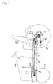
- Fig. 1 is a side view of a vehicle loading thereon a first embodiment of an axle driving apparatus of the present invention;
- Fig. 2 is a side view of the axle driving apparatus of the present invention;
- Fig. 3 is a plan view thereof;
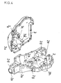
- Fig. 4 is a perspective view of a casing M, which is separated into a
casing half 3 and acasing half 2; - Fig. 5 is a plan view showing the interior of
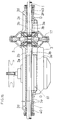
casing half 2 from whichcasing half 3 has been separated along [lie junction plane D - D in Figure 2; - Fig. 6 is a sectional view taken on the line A - A in Fig. 3;
- Fig. 7 is a sectional view taken on the line C - C in Fig. 3;
- Fig. 8 is a sectional view taken on the line B - B in Fig. 5, showing a holding portion for the
axle 1; - Fig. 9 is a sectional view taken on the line E - E in Fig. 5;
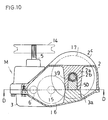
- Fig. 10 is a sectional side view of a modified embodiment of construction of bearing for the
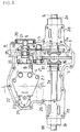
axle 1; - Fig. 11 is an external plan view of a second embodiment of an axle driving apparatus of the present invention, partially cutaway at the
casing half 2 by the plane including the axis of theaxle 1; - Fig. 12 is a sectional view of the axle driving apparatus taken on the line H - H in Fig. 11;
- Fig. 13 is a sectional view of the same taken on the line I - I in Fig. 11;
- Fig. 14 is a sectional view of the same taken on the line J - J in Fig. 11;
- Fig. 15 is a sectional view of the same taken on the line K - K in Fig. 11;
- Fig. 16 is a perspective exploded view of a differential gear; and
- Fig. 17 is a perspective exploded view of a brake device.
- In Figs. 1 and 2, within a
bonnet 44 of a vehicle is disposed avertical type engine 11 whoseengine output shaft 45 is vertically disposed. Apulley 46 is fixed to theengine output shaft 45.Input pulley 14 is fixed to aninput shaft 5 projecting from a casing M of the axle driving apparatus. Abelt transmission mechanism 13 is disposed between bothpulleys input shaft 5 and output shaft 6), anaxle 1, and a gear for connecting the transmission andaxle 1 in association therewith. Casing M is filled with operating oil for the hydraulic non-stage transmission. - The
engine 11 is disposed at the front of abody frame 12. The casing M hangs downwardly from the rear ofbody frame 12 throughmounting brackets 2d.Driving wheels 42 are fixed toaxles 1 laterally projecting from the casing M. In addition,front steering wheels 41 and aseat 43 are also shown. In the embodiment in Fig. 1,engine 11 is of a vertical type which vertically disposes theengine output shaft 45, so thatbelt transmission mechanism 13 is used to transmit power to the laterally disposed casing M. In the alternative, when theengine output shaft 45 is positioned horizontally, a power transmitting shaft using an universal joint may be provided to transmit the power to inputshaft 5 which horizontally projects from vertically disposed casing M. - Casing M is formed by joining at least one
casing half 2 with anothercasing half 3. The axis ofoutput shaft 6 of the hydraulic non-stage transmission and that ofaxle 1 are disposed within casing M. The plane including the axis ofoutput shaft 6 is coincident with the junction surface D -D casing halves M. Output shaft 6 is journalled at the junction portion. The axis ofaxle 1 is not positioned at the junction surface D - D, but is positioned at a side ofcasing half 2. Anaxle housing 2e is integrally provided outsidecasing half 2. Axle 1 is rotatably supported at the outside or distal end thereof tohousing 2e through abearing 40.Mounting brackets 2d are provided at the upper and lower surfaces ofaxle housing 2e so as to fixhousing 2e tobody frame 12 of the vehicle from the upper or lower surface thereof. In addition, acover 20 is provided for a braking device provided at the utmost end ofoutput shaft 6. Referring to Fig. 3, a speedchange operating arm 26 is fixed to a speedchange operating shaft 27 upwardly projecting from the upper surface ofcasing half 2. A by-passvalve operating arm 24 is fixed to a by-passvalve operating shaft 48. - In Fig. 4, the casing M is shown separated into
casing halves body frame 12,casing half 2 is upwardly mounted andcasing half 3 is downwardly mounted. A pair ofprojections 3a, for supportingaxle 1 from below at the inside portion thereof throughbearings 39, project upwardly beyond junction surface D - D. Withincasing half 2, a pair ofholders 2a for supporting theaxle 1 at the inside or proximal portion thereof through thebearings 39 are formed downwardly before the junction surface D - D. Swollen or enlarged regions orportions 3c and 2f for supporting bearings for acounter shaft 15 project close to junction surface D - D ofcasing M. Bosses 2h for mounting therethrough a hydraulic non-stage transmission project from thecasing half 2 to the position of junction surface D -D. Supports 3e and 2g for supporting a bearing foroutput shaft 6 project to the junction surface D -D. Mounting brackets 2d at the axle housings each are formed in a plane level with junction surface D - D of casing M. - Referring to Fig. 5, the casing M is shown from which
casing half 3 has been removed, andcasing half 2 is shown as viewed from below. Within casinghalf 2, amanifold 4 for the hydraulic non-stage transmission is fixed to thebosses 2h through bolts. Themanifold 4 connects a hydraulic pump and a hydraulic motor through a closed circuit so as to constitute a hydraulic non-stage transmission.Manifold 4 is nearly L-like-shaped as shown in Fig. 6. The hydraulic pump, which is mounted on the upper surface ofmanifold 4, is not shown in Fig. 5. Meanwhile, acylinder block 8 of the hydraulic motor is mounted at the side surface ofmanifold 4.Output shaft 6 integral with thecylinder block 8, is supported bysupport 2g through a bearing. Agear 35 is formed at an intermediate portion ofoutput shaft 6. A drum-like brakedrotary member 19 is fixed to the utmost end ofoutput shaft 6, projecting outwardly from casing M. Around the brakedrotary member 19 is provided a band-like braking member 21 press-contactable with the brakedrotary member 19. - A
countershaft 15, provided with alarger diameter gear 16 engageable withgear 35 and asmaller diameter gear 18, is disposed atswollen portion 2f. - A differential gear, including a
ring gear 17 engageable withsmaller diameter 18, is housed incasing half 2. The differential gear comprises a pair ofpinions 37 mounted integrally withring gear 17 and a pair of side gears 36 engageable with pinions 37. - A pair of
axles 1 are inserted intocasing half 2 throughaxle housings 2e and are held at the inside portion thereof and abut at their utmost ends against each other and at the same time engage with side gears 36, respectively. - In addition, a pair of by-
pass operating valves 22 project frommanifold 4. A horse-shoetype operating member 23 is disposed in front of the operatingvalves 22. Operatingmember 23 is retained to aneccentric operating shaft 25 mounted to the by-passvalve operating shaft 48 so that a by-passvalve operating arm 24 is optionally rotated to move the operatingmember 23. As the pair of by-pass operating valves 22 are depressed, they enable operating oil to be discharged from the closed circuit in themanifold 4 to casing M. - As shown in Fig. 6, at the junction surface D - D of casing
half 2 andcasing half 3,manifold 4 is fixed from below toboss 2h. At the upper surface ofmanifold 4 is supported acylinder block 7 together withinput shaft 5. A plurality ofpump pistons 32 are inserted into a plurality of cylinder bores bored atcylinder block 7. Amovable swash plate 28 abuts against the tops ofpump pistons 32. As shown in Fig. 9,movable swash plate 28 can be tilted by alever arm 30 and alever 31 through speedchange operating arm 26 and speedchange operating shaft 27.Cylinder block 7 is subjected to power and rotates throughinput pulley 14 andinput shaft 5 so as to take in and discharge operating oil in casing M. - On the other hand, the
cylinder block 8 of the hydraulic motor is supported to the side surface ofmanifold 4. Pressure oil from the hydraulic pump is supplied through an oil passage inmanifold 4 to a plurality of cylinder bores bored incylinder block 8. The pressure oil serves as a force to pushmotor pistons 33, fitted into the cylinder bores, whereby, the pushing force is converted into a torque by fixedswash plate 34 so as to rotatecylinder block 8 andoutput shaft 6. Anoil filter 29 is disposed between the lower surface ofmanifold 4 and the inner bottom surface ofcasing half 3. The operating oil filtered byoil filter 29 is used to supply the pressure oil in the closed circuit ofmanifold 4. At thebody frame 12 of the vehicle is fixed the casing M through the mountingbracket 2d. Swollen or enlarged region orportion 2c ofcasing half 2 and inputpulley 14 attached to inputshaft 5 are at about level with and housed withinbody frame 12. - Referring to Fig. 7, in the axle driving apparatus of the present invention, the outside or distal portion of
axle 1 is supported toaxle housing 2e of casinghalf 2 throughbearing 40. The inside or proximal portion ofaxle 1 is supported bybearings 39 sandwiched betweensemicircular recesses 2b formed at theholders 2a of thecasing half 2 andsemicircular recesses 3b formed at theprojections 3a projecting from casinghalf 3 toward thecasing half 2. Hence, the axis ofaxle 1 is not in the plane D - D at the junction surface betweencasing halves output shaft 6 andcounter shaft 15 are positioned in plane D - D as shown in Fig. 8. - If, when casing
halves holders 2a andprojections 3a meet before the remainder of the casing, the casing halves 2 and 3 cannot be completely joined. As a result, when both casing halves are forcibly tightened, the casing M becomes loose. Therefore, as shown in Figs. 8 and 9, when casinghalves holders 2a andprojections 3a. In other words, an inner diameter of each bearingportion holding axle 1 is larger than the sum of the depths ofrecesses - Referring to Fig. 10, a modified embodiment of an axle holding portion is shown, in which each
holder 2a at casinghalf 2 and eachprojection 3a projecting from casinghalf 3 extend up to the junction surface of the casing.Recess 2b at eachholder 2a is made larger in depth and abearing support 50 is inserted into thecasing half 2. - Such construction also can support
bearing 39 between the upper end of bearingsupport 50 andrecess 2b, so as tojournal axle 1 throughbearing 39. - A second embodiment is similar to the first described embodiment with respect to casing M being separated into two parts, the provision of a hydraulic non-stage transmission, and a positional relationship between
output shaft 6 andaxle 1. Like components are designated by like reference numerals and a detailed description thereof is omitted. - Fig. 11 is an exterior plan view of the second embodiment of the axle driving apparatus of the present invention in which
casing half 2 is partially cutaway at the plane including the axis ofaxles 1. In this embodiment a hydraulic motor of the hydraulic non-stage transmission type is larger in capacity than the hydraulic pump to thereby obtain hydraulic speed reduction. Therefore, the counter shaft shown in the first embodiment is omitted andgear 35 atoutput shaft 6 directly engages withring gear 17 of the differential gear. - Casing M is partitioned into a
chamber 60 for housing therein the hydraulic non-stage transmission and achamber 61 housing therein the differential gear andaxles 1. A sealingbearing 51 is used for supportingoutput shaft 6 so that oil is prevented from moving in reciprocation between the hydraulic motor andgear 35, that is, between thechambers chamber 60 and the lubricating oil for the differential gear andaxles 1 fillschamber 61. - The support for the inside or proximal portion of the axle in this embodiment is best seen in Fig. 13. A
semicircular recess 2b is formed at aholder 2a and asemicircular recess 3b is formed atprojection 3a, so that the holding portion is directly held byrecesses holder 2a andprojection 3a is provided a gap t, as in the first embodiment. Lubricating oil sufficiently reaches the frictional potion of the transmission through gap t. -
Bearing 40, for supporting the outside or distal portion ofaxle 1, uses a bush type bearing and is disposed at the outer end of a hollow of theaxle housing 2e. The hollow, which is not formed by mechanical machining, but rather, is casted during molding ofcasing half 2, is tapered inwardly ofcasing half 2. - Again referring to Fig. 11, the differential gear and axes 1, a
pinion shaft 38 pivotally supporting apinion 37 is fitted into aring gear 17. Assembly of thepinion 37 engaging with differential side gears 36 is held inchamber 61.Axles 1 are inserted therein throughaxle housings 2e and are coupled in spline with differential side gears 36, respectively. Snap rings 62, shaped as shown in Fig. 16, are inserted betweenaxles 1 andpinion shaft 38 and are retained into grooves ataxles 1, respectively, thereby completely positioningaxles 1. Snap rings 62 each have atongue 62a bent outwardly in part and engaged with a groove provided at eachside gear 36 so as to preventsnap ring 62 from escaping from therespective axles 1. - Next, explanation will be given on a braking device of the axle driving apparatus. At the end of
output shaft 6 is fixed a rotary diskbrake type member 19. A biasingmember 63 is disposed at the front side ofmember 19 and a fixedbraking surface 2i projects from casinghalf 2 at the rear side of the same. Biasingmember 63, as shown in Fig. 17, comprises apivotal shaft 63a, a pair ofcam projections 63b, and anarm 63c connected to a brake operating member (not shown). Abracket 64 for supporting [lie biasingmember 63 is tightened to a disposingsurface 3f for disposingcasing half 3 through twobolts 65.Bracket 64, having abore 64a into which thepivotal shaft 63a is fitted and a cam groove 64b with which thecam projection 63b comes into slidable contact. Whenarm 63c is subjected to an external force and biasingmember 63 rotates aroundpivotal shaft 63a,cam projections 63b ride on a shallow portion of cam groove 64b from a deep portion thereof and biasingmember 63 moves in the direction of pushingmember 19, thereby exerting a braking action tomember 19 between fixedbraking surface 2i andmember 19. Anelastic wire rod 66 is fixed at its base tobracket 64 and is bent at an idle end to abut against both axial ends ofarm 63. Hence, when no external force is applied thereto,cam projections 63b are biased to be positioned at the deep portion of cam groove 64b. - Each
casing half - The present invention has the following advantages:
- Since
axles 1 are journalled to onecasing half 2, theaxles 1 are not positioned at the junction surface D - D. Thereby, even if casinghalf 3 is removed,axles 1 remain in onecasing half 2, thereby facilitating assembly and dismantling of the hydraulic non-stage transmission. - Since the axis of each
axle 1 is not on the junction surface D - D of casing M, but is in one casing half and the axis ofoutput shaft 6 connected in association withaxle 1 is disposed on the junction surface D - D, the interval betweenaxle 1 andoutput shaft 6 when viewed in plan can be reduced. Hence, a compact axle driving apparatus is obtainable. Since the bearing foraxle 1 is provided in a single casing half, the rigidity of the bearing is improved. For maintenance and inspection of the hydraulic non-stage transmission, whileaxles 1 remain in one casing half, the other casing half need only be removed, thereby enabling the hydraulic non-stage transmission to be simply dismantled or assembled. - Since the hydraulic non-stage transmission is so constructed that the axes of
input shaft 5 andoutput shaft 6 intersect approximately perpendicularly with each other andaxles 1 are pivoted tocasing half 2 for supporting the input end ofoutput shaft 5, the axle driving apparatus of the invention has the following effect: The axis ofaxle 1 is nearer to the axial end ofinput shaft 5 of the hydraulic non-stage transmission, whereby the volume ofcasing half 3 which does not supportinput shaft 5 can correlatively be reduced. - Also, input
pulley 14 is fixed to inputshaft 5 and is connected in association withengine 11 throughbelt transmitting mechanism 13.Swollen portion 2c for housing the differential gear connecting the left andright axles 1 is formed in onecasing half 2 in a manner of superposing with respect topulley 14 when viewed laterally. In other words, sinceinput pulley 14 atinput shaft 5 can be lowered relative toaxle 1, the center of gravity ofengine 11 loaded on the vehicle can be disposed in a lower position and a stable vehicle with a low center of gravity can be obtained. Also, the hydraulic non-stage transmission, which is disposed in a relatively lower position in casing M with respect to theaxle 1, can be immersed in oil within casing M, and the closed circuit of the hydraulic non-stage transmission can be prevented from taking in air, whereby the phenomenon of cavitation can be avoided and the performance of the axle driving apparatus can be improved. -
Outside casing half 2 are integrally providedaxle housings 2e approximately coaxially withaxles 1 so as to supportaxles 1. Theother casing half 3 is made asymmetrical with respect tocasing half 2 and is of diminished volume, whereby, casinghalf 2 is strong enough to supportaxles 1 andcasing half 3 can be a simple lid smaller in volume and of an oil-pan-like shape in comparison withcasing half 2. Mountingbrackets 2d can be provided to improve the strength ofaxle housing 2e. - The outside portion of each
axle 1 is supported by bearing 40 held toaxle housing 2e and the inside portion of the same is supported by the holding portion formed by the junction of the two casing halves, whereby, bearing 40 provided ataxle housing 2e temporarily holds eachaxle 1 at a side ofcasing half 2.Casing half 3 is joined withcasing half 2 so thataxles 1 are completely supported within casing M, thereby simplifying the assembly ofaxles 1. - The above-mentioned holding portion is formed in such a manner that
recess 2b ofholder 2a provided withincasing half 2 andrecess 3b ofprojection 3a provided withincasing half 3 are opposite to each other, whereby recesses 2b and 3b can integrally and simultaneously be formed when the casing halves are molded respectively and the holding portion is simple in construction. - In addition, the holding portion may support
axles 1 through bearing 39 as shown in the first embodiment, or directly and not through the bearing as shown in the second embodiment. - An inner diameter of the holding portion is set large than the sum of the depths of
recesses holder 2a andprojection 3a when couplingcasing halves recesses holders 2a andprojections 3a with each other making it impossible to joincasing halves - The transmission means for connecting
output shaft 6 of the hydraulic non-stage transmission in association withaxles 1 uses a spur gear. However, a bevel gear or an endless band, such as a belt or a chain, may be used instead of the spur gear. - Furthermore, the hydraulic non-stage transmission shown housed within casing M is only one example of a mechanism for steplessly speed-change-driving
axles 1. Alternatively, the axle driving apparatus being adapted to house therein a mechanical non-stage transmission, a mechanical transmission in need of stepwise speed-change-driving the axles, or a speed reduction mechanism only for driving the same, would not depart from the principle of the present invention.
Claims (14)
- An axle driving apparatus for a vehicle comprising:first and second casing sections (2,3) joined along a junction surface (D-D) to form a casing (M), wherein the junction surface (D-D) of said first and second casing sections (2,3) defines a first plane;a speed-changing transmission mechanism disposed within said casing (M) having an input shaft (5) to which engine power is transmitted from an engine (11) of the vehicle and an output shaft (6) through which said engine power is transmitted out of said transmission mechanism; andan axle (1) for propulsion of wheels of the vehicle, said axle (1) being drivingly connected to said ouput shaft (6) of said transmission mechanism, wherein said casing (M) provides a housing for both said transmission mechanism and said axle (1),
characterized in thatsaid axle (1) is rotatably supported by one of said first and second casing sections (2,3), such that the longitudinal axis of said axle (1) is disposed in a second plane which lies parallel to said first plane at a side of said one of the first and second casing sections (2,3). - The axle driving apparatus according to claim 1, wherein a transmission means is provided within said casing (M) for drivingly connecting said output shaft (6) to said axle (1) and the longitudinal axis of said output shaft (6) is disposed in a plane different from said second plane.
- The axle driving apparatus according to claim 2, whereinsaid casing (M) further comprises an enlarged region (2c);said transmission means comprises a gear (17) housed within said enlarged region (2c) for drivingly connecting said axles (1) to said output shaft (6); andan input pulley (14) is provided adjacent said enlarged region (2c) outside said casing (M) for inputting the engine power through a belt transmission mechanism (13) to said input shaft (5) of said speed-changing transmission mechanism.
- The axle driving apparatus according to claim 2, wherein said transmission means comprises a counter shaft (15) disposed between said output shaft (6) and said axle (1), wherein the longitudinal axis of said counter shaft (15) is disposed within said first plane.
- The axle driving apparatus according to one of the preceding claims, wherein said longitudinal axis of said output shaft (6) is disposed within said first plane.
- The axle driving apparatus according to one of the preceding claims, wherein said input shaft (5) is rotatably supported by said casing (M) and the longitudinal axis of said input shaft (5) is disposed perpendicular to said longitudinal axis of said axle (1).
- The axle driving apparatus according to one of the preceding claims, further comprisingmeans (2e, 40), disposed within said casing (M), for holding a distal portion of said axle (1); andmeans (2a, 3a), disposed within said casing (M), for holding a proximal portion of said axle (1).
- The axle driving apparatus according to claim 7, wherein said means (2e, 40) for holding the distal portion of said axle (1) comprises an axle housing (2e) including a hollow and a bearing (40) fitted into said hollow.
- The axle driving apparatus according to claim 8, wherein said axle housing (2e) projects outwardly from a side wall of said one of the first and second casing sections (2, 3) supporting said axle (1) and is integral therewith.
- The axle driving apparatus according to claim 7, 8 or 9, wherein said means (2a, 3a) for holding the proximal portion of said axle (1) comprisesa holder (2a) formed in one of said first and second casing sections (2, 3); anda projection (3a) formed in the other of said first and second casing setions (3, 2), wherein said holder (2a) and said projection (3a) are disposed opposite to each other.
- The axle driving apparatus according to claim 10, further comprisinga first substantially semicircular recess (2b) formed in said holder (2a); anda second substantially semicircular recess (3b) provided at the utmost end of said projection (3a), wherein said projection (3a) extends beyond the first plane defined by the junction surface (D-D) of said casing sections (2, 3).
- The axle driving apparatus according to claim 11, further comprising a bearing (39) sandwiched between said first and second substantially semicircular recesses (2b, 3b), whereby said axle (1) is supported through said bearing (39), and wherein the outer diameter of said bearing (39) is larger than the total depth of said first and second substantially semicircular recesses (2b, 3b).
- The axle driving apparatus according to claim 11, wherein said axle (1) is directly supported by said first and second semicircular recesses (2b, 3b) and wherein the outer diameter of said axle (1) is larger than the total depth of said first and second substantially semicircular recesses (2b, 3b).
- The axle driving apparatus according to one of the preceding claims, wherein said speed-changing transmission mechanism disposed within said casing (M) comprises a hydraulic non-stage transmission.
Applications Claiming Priority (2)
| Application Number | Priority Date | Filing Date | Title |
|---|---|---|---|
| JP3335226A JPH06270705A (en) | 1991-12-18 | 1991-12-18 | Axle driving device |
| JP335226/91 | 1991-12-18 |
Publications (2)
| Publication Number | Publication Date |
|---|---|
| EP0547395A1 EP0547395A1 (en) | 1993-06-23 |
| EP0547395B1 true EP0547395B1 (en) | 1997-02-05 |
Family
ID=18286161
Family Applications (1)
| Application Number | Title | Priority Date | Filing Date |
|---|---|---|---|
| EP92119721A Expired - Lifetime EP0547395B1 (en) | 1991-12-18 | 1992-11-19 | Axle driving apparatus |
Country Status (4)
| Country | Link |
|---|---|
| US (2) | US5335496A (en) |
| EP (1) | EP0547395B1 (en) |
| JP (1) | JPH06270705A (en) |
| DE (1) | DE69217339T2 (en) |
Families Citing this family (45)
| Publication number | Priority date | Publication date | Assignee | Title |
|---|---|---|---|---|
| US6938718B1 (en) | 1988-02-03 | 2005-09-06 | Kanzaki Kokyukoki Mfg. Co., Ltd. | Axle driving apparatus |
| US20050217919A1 (en) * | 1988-02-03 | 2005-10-06 | Hiedeaki Okada | Axle driving apparatus |
| US4932209A (en) * | 1988-02-03 | 1990-06-12 | Kanzaki Kokyukoki Mf. Co. Ltd. | Axle driving apparatus |
| JPH06270705A (en) * | 1991-12-18 | 1994-09-27 | Kanzaki Kokyukoki Mfg Co Ltd | Axle driving device |
| JPH0783161A (en) * | 1993-09-17 | 1995-03-28 | Kanzaki Kokyukoki Mfg Co Ltd | Variable displacement type axial piston machine |
| US6390227B1 (en) | 1995-03-30 | 2002-05-21 | Kanzaki Kokyukoki Mfg. Co., Ltd. | Axle driving unit for a lawn tractor |
| US5613409A (en) * | 1995-04-28 | 1997-03-25 | Hydro-Gear Limited Partnership | Axle driving apparatus having improved casing design |
| US5622051A (en) * | 1995-06-26 | 1997-04-22 | Kanzaki Kokyukoki Mfg. Co., Ltd. | Axle driving apparatus with cooling tubing |
| US6385971B1 (en) | 1995-10-27 | 2002-05-14 | Tuff Torq Corporation | Axle driving apparatus |
| JP2000508408A (en) * | 1995-10-27 | 2000-07-04 | タフトルク コーポレイション | Axle drive |
| US6125630A (en) * | 1995-10-27 | 2000-10-03 | Tuff Torq Corporation | Axle driving apparatus |
| US5782142A (en) * | 1996-04-12 | 1998-07-21 | Tuff Torq Corporation | Axle driving apparatus |
| US5819537A (en) * | 1996-12-02 | 1998-10-13 | Kanzaki Kokyukoki Mfg. Co., Ltd. | Axle driving apparatus |
| US5992150A (en) * | 1996-12-23 | 1999-11-30 | Tecumseh Products Company | Transaxle with hydrostatic transmission |
| US6449949B1 (en) * | 1997-03-12 | 2002-09-17 | Kanzaki Kokyukoki Mfg. Co., Ltd. | Axle driving system |
| US7192376B2 (en) * | 1997-03-12 | 2007-03-20 | Norihiro Ishii | Axle driving apparatus |
| JP2001514598A (en) | 1997-03-12 | 2001-09-11 | 株式会社神崎高級工機製作所 | Axle drive |
| US6105463A (en) | 1997-07-24 | 2000-08-22 | Hydro-Gear Limited Partnership | Transmission and transaxle casing |
| US5980416A (en) * | 1997-08-06 | 1999-11-09 | Sven B. Gafvert | Differential for a vehicle |
| DE19800002A1 (en) * | 1998-01-02 | 1999-07-08 | Linde Ag | Hydrostatic unit to drive work machine e.g. for fork lift truck |
| EP1028020A3 (en) | 1999-02-09 | 2003-03-26 | Tecumseh Products Company | Hydrostatic transmission having two-piece pump and motor block assembly |
| US6793463B1 (en) | 2000-10-30 | 2004-09-21 | Hydro-Gear Limited Partnership | Tandem pump and interface for same |
| US6494686B1 (en) | 2000-10-30 | 2002-12-17 | Hydro-Gear Limited Partnership | Tandem pump and interface for same |
| GB0106002D0 (en) | 2001-03-12 | 2001-05-02 | Hansen Transmissions Int | Support for a gear bearing elements |
| US6662538B2 (en) * | 2001-08-28 | 2003-12-16 | Commerical Turf Products, Ltd. | Lawn mower main frame and sub-frame assembly |
| US7383683B1 (en) | 2002-07-31 | 2008-06-10 | Hydro-Gear Limited Partnership | Zero-turn hydrostatic transaxle |
| US6775976B1 (en) | 2002-07-31 | 2004-08-17 | Hydro-Gear Limited Partnership | Zero-turn hydrostatic transaxle |
| JP4115227B2 (en) * | 2002-09-26 | 2008-07-09 | 株式会社クボタ | Mower |
| DE20217296U1 (en) * | 2002-11-09 | 2004-03-18 | Haver & Boecker | wire cloth |
| US6953327B1 (en) | 2003-03-11 | 2005-10-11 | Hydro-Gear Limited Partnership | Dual pump |
| US7240488B2 (en) * | 2005-02-02 | 2007-07-10 | Masaru Iida | Cruise control and neutral return mechanism for a hydrostatic transmission |
| US7331176B1 (en) * | 2005-04-19 | 2008-02-19 | Kanzaki Koyukoki Mfg. Co., Ltd. | Transaxle |
| US7257948B1 (en) | 2005-12-21 | 2007-08-21 | Hydro-Gear Limited Partnership | Dual pump apparatus |
| US7726126B1 (en) | 2005-12-21 | 2010-06-01 | Hydro-Gear Limited Partnership | Dual pump apparatus with power take off |
| US7921643B2 (en) * | 2008-01-11 | 2011-04-12 | Kanzaki Kokyukoki Mfg. Co., Ltd. | Hydrostatic transaxle |
| US8857171B2 (en) * | 2010-02-11 | 2014-10-14 | Parker-Hannifin Corporation | Integrated hydrostatic transmission |
| EP2372192A1 (en) * | 2010-03-31 | 2011-10-05 | Winergy AG | Branched drive for a wind turbine |
| DE102010019392B3 (en) * | 2010-05-04 | 2011-11-10 | Voith Patent Gmbh | Drive unit for rail vehicles |
| DE102011003525A1 (en) * | 2011-02-02 | 2012-08-02 | Siemens Aktiengesellschaft | Stepped parting line on a gearbox |
| JP6611806B2 (en) * | 2014-11-21 | 2019-11-27 | フォイト パテント ゲゼルシャフト ミット ベシュレンクテル ハフツング | Transmission and turbomachine with transmission |
| US11172610B2 (en) * | 2016-08-31 | 2021-11-16 | Kaaz Corporation | Transmission for lawn mower |
| CN111075910A (en) * | 2020-01-09 | 2020-04-28 | 精进电动科技(菏泽)有限公司 | A reducer box structure |
| CN112498101A (en) * | 2020-12-11 | 2021-03-16 | 徐工集团工程机械股份有限公司道路机械分公司 | Tire walking driving system and paver |
| CN114110142B (en) * | 2021-11-24 | 2025-12-02 | 中车大连机车车辆有限公司 | A two-stage transmission gearbox |
| CN115507165A (en) * | 2022-09-28 | 2022-12-23 | 天津特智履研究开发有限公司 | An assembled clamping structure for the main shaft of an engineering vehicle |
Citations (1)
| Publication number | Priority date | Publication date | Assignee | Title |
|---|---|---|---|---|
| US5156576A (en) * | 1991-05-22 | 1992-10-20 | Sauer, Inc. | Compact integrated transaxle |
Family Cites Families (15)
| Publication number | Priority date | Publication date | Assignee | Title |
|---|---|---|---|---|
| FR535535A (en) * | 1920-05-18 | 1922-04-15 | Argus Motoren G M B H | Improvements to casings and engine mechanisms for motor vehicles |
| GB805771A (en) * | 1955-08-16 | 1958-12-10 | Daimler Benz Ag | Improvements in hydrostatic power transmission arrangements comprising rockable pumpand motor elements |
| JPS6357331A (en) * | 1986-08-28 | 1988-03-12 | Kawasaki Heavy Ind Ltd | Continuously variable power transmission gear |
| US4870820A (en) * | 1987-04-15 | 1989-10-03 | Kanzaki Kokyukoki Mfg. Co. Ltd. | HST (hydro-static-transmission) system driving speed changing apparatus |
| US4922787A (en) * | 1987-06-26 | 1990-05-08 | Kanzaki Kokyukoki Mfg. Co. Ltd. | HST (hydrostatic transmission) housing axle driving apparatus |
| JPS644520A (en) * | 1987-06-27 | 1989-01-09 | Kanzaki Kokyukoki Mfg Co Ltd | Hst integral type axle driving device |
| US4979583A (en) * | 1987-07-04 | 1990-12-25 | Thoma Christian H | Variable speed transaxle |
| JPH0519225Y2 (en) * | 1987-11-21 | 1993-05-20 | ||
| US4932209A (en) * | 1988-02-03 | 1990-06-12 | Kanzaki Kokyukoki Mf. Co. Ltd. | Axle driving apparatus |
| JP2672962B2 (en) * | 1988-02-03 | 1997-11-05 | 株式会社神崎高級工機製作所 | Axle drive |
| JP2677580B2 (en) * | 1988-02-03 | 1997-11-17 | 株式会社神崎高級工機製作所 | Axle drive |
| US4986073A (en) * | 1988-02-03 | 1991-01-22 | Kanzaki Kokyukoki Mfg. Co., Ltd. | Axle driving apparatus |
| US4903545A (en) * | 1989-03-03 | 1990-02-27 | Sundstrand-Sauer | Hydrostatic transmission center section |
| US5078659A (en) * | 1989-12-11 | 1992-01-07 | Unipat Ag | Variable speed transaxle |
| JPH06270705A (en) * | 1991-12-18 | 1994-09-27 | Kanzaki Kokyukoki Mfg Co Ltd | Axle driving device |
-
1991
- 1991-12-18 JP JP3335226A patent/JPH06270705A/en active Pending
-
1992
- 1992-04-07 US US07/864,932 patent/US5335496A/en not_active Expired - Lifetime
- 1992-11-19 DE DE69217339T patent/DE69217339T2/en not_active Expired - Lifetime
- 1992-11-19 EP EP92119721A patent/EP0547395B1/en not_active Expired - Lifetime
-
1994
- 1994-06-01 US US08/251,971 patent/US5447028A/en not_active Expired - Lifetime
Patent Citations (2)
| Publication number | Priority date | Publication date | Assignee | Title |
|---|---|---|---|---|
| US5156576A (en) * | 1991-05-22 | 1992-10-20 | Sauer, Inc. | Compact integrated transaxle |
| US5156576B1 (en) * | 1991-05-22 | 1994-08-30 | Sauer Inc | Compact integrated transaxle |
Also Published As
| Publication number | Publication date |
|---|---|
| DE69217339T2 (en) | 1997-07-03 |
| US5335496A (en) | 1994-08-09 |
| JPH06270705A (en) | 1994-09-27 |
| EP0547395A1 (en) | 1993-06-23 |
| US5447028A (en) | 1995-09-05 |
| DE69217339D1 (en) | 1997-03-20 |
Similar Documents
| Publication | Publication Date | Title |
|---|---|---|
| US5335496A (en) | Axle driving apparatus | |
| US5752417A (en) | Axle driving apparatus | |
| US4905472A (en) | Axle driving apparatus | |
| US4922787A (en) | HST (hydrostatic transmission) housing axle driving apparatus | |
| US4870820A (en) | HST (hydro-static-transmission) system driving speed changing apparatus | |
| US4914907A (en) | Axle driving apparatus | |
| US7806667B1 (en) | Dual pump | |
| US7621125B2 (en) | Axle driving system | |
| JPH0648198A (en) | Hydraulic transaxle | |
| US5377487A (en) | Axle driving apparatus having offset output shaft | |
| US6786042B2 (en) | Axle driving apparatus | |
| EP1348588B1 (en) | Axle driving apparatus | |
| EP0966363B1 (en) | Axle driving system | |
| US7017446B1 (en) | Axle driving apparatus | |
| US20050217919A1 (en) | Axle driving apparatus | |
| US6938718B1 (en) | Axle driving apparatus | |
| JP2599737B2 (en) | HST axle drive | |
| JP3065770B2 (en) | Vehicle powertrain structure | |
| JP2582414Y2 (en) | Axle drive | |
| JPH1081150A (en) | Transmission of self-running working machine | |
| JP2667126B2 (en) | Axle drive | |
| JP2944555B2 (en) | Axle drive | |
| JPH06211059A (en) | Hst-integrated axle driving device | |
| JPH0757576B2 (en) | HST integrated axle drive |
Legal Events
| Date | Code | Title | Description |
|---|---|---|---|
| PUAI | Public reference made under article 153(3) epc to a published international application that has entered the european phase |
Free format text: ORIGINAL CODE: 0009012 |
|
| AK | Designated contracting states |
Kind code of ref document: A1 Designated state(s): DE FR |
|
| 17P | Request for examination filed |
Effective date: 19931223 |
|
| 17Q | First examination report despatched |
Effective date: 19950110 |
|
| GRAG | Despatch of communication of intention to grant |
Free format text: ORIGINAL CODE: EPIDOS AGRA |
|
| GRAH | Despatch of communication of intention to grant a patent |
Free format text: ORIGINAL CODE: EPIDOS IGRA |
|
| GRAH | Despatch of communication of intention to grant a patent |
Free format text: ORIGINAL CODE: EPIDOS IGRA |
|
| GRAA | (expected) grant |
Free format text: ORIGINAL CODE: 0009210 |
|
| AK | Designated contracting states |
Kind code of ref document: B1 Designated state(s): DE FR |
|
| REF | Corresponds to: |
Ref document number: 69217339 Country of ref document: DE Date of ref document: 19970320 |
|
| ET | Fr: translation filed | ||
| PLBE | No opposition filed within time limit |
Free format text: ORIGINAL CODE: 0009261 |
|
| STAA | Information on the status of an ep patent application or granted ep patent |
Free format text: STATUS: NO OPPOSITION FILED WITHIN TIME LIMIT |
|
| 26N | No opposition filed | ||
| PGFP | Annual fee paid to national office [announced via postgrant information from national office to epo] |
Ref country code: FR Payment date: 20111125 Year of fee payment: 20 |
|
| PGFP | Annual fee paid to national office [announced via postgrant information from national office to epo] |
Ref country code: DE Payment date: 20120131 Year of fee payment: 20 |
|
| REG | Reference to a national code |
Ref country code: DE Ref legal event code: R071 Ref document number: 69217339 Country of ref document: DE |
|
| REG | Reference to a national code |
Ref country code: DE Ref legal event code: R071 Ref document number: 69217339 Country of ref document: DE |