EP0546863A2 - Data compression apparatus - Google Patents
Data compression apparatus Download PDFInfo
- Publication number
- EP0546863A2 EP0546863A2 EP92311359A EP92311359A EP0546863A2 EP 0546863 A2 EP0546863 A2 EP 0546863A2 EP 92311359 A EP92311359 A EP 92311359A EP 92311359 A EP92311359 A EP 92311359A EP 0546863 A2 EP0546863 A2 EP 0546863A2
- Authority
- EP
- European Patent Office
- Prior art keywords
- data
- data words
- word
- words
- cell
- Prior art date
- Legal status (The legal status is an assumption and is not a legal conclusion. Google has not performed a legal analysis and makes no representation as to the accuracy of the status listed.)
- Withdrawn
Links
Images


Classifications
-
- H—ELECTRICITY
- H03—ELECTRONIC CIRCUITRY
- H03M—CODING; DECODING; CODE CONVERSION IN GENERAL
- H03M7/00—Conversion of a code where information is represented by a given sequence or number of digits to a code where the same, similar or subset of information is represented by a different sequence or number of digits
- H03M7/30—Compression; Expansion; Suppression of unnecessary data, e.g. redundancy reduction
- H03M7/3084—Compression; Expansion; Suppression of unnecessary data, e.g. redundancy reduction using adaptive string matching, e.g. the Lempel-Ziv method
-
- G—PHYSICS
- G06—COMPUTING; CALCULATING OR COUNTING
- G06T—IMAGE DATA PROCESSING OR GENERATION, IN GENERAL
- G06T9/00—Image coding
- G06T9/005—Statistical coding, e.g. Huffman, run length coding
-
- H—ELECTRICITY
- H03—ELECTRONIC CIRCUITRY
- H03M—CODING; DECODING; CODE CONVERSION IN GENERAL
- H03M7/00—Conversion of a code where information is represented by a given sequence or number of digits to a code where the same, similar or subset of information is represented by a different sequence or number of digits
- H03M7/30—Compression; Expansion; Suppression of unnecessary data, e.g. redundancy reduction
- H03M7/3084—Compression; Expansion; Suppression of unnecessary data, e.g. redundancy reduction using adaptive string matching, e.g. the Lempel-Ziv method
- H03M7/3086—Compression; Expansion; Suppression of unnecessary data, e.g. redundancy reduction using adaptive string matching, e.g. the Lempel-Ziv method employing a sliding window, e.g. LZ77
Definitions
- the present invention is directed to an apparatus for compressing and decompressing strings of data words.
- Figs. 1A-1C of the accompanying drawings illustrate a typical implementation of the Lempel-Ziv algorithm.
- a shift register 10 that is N+1 bytes long is used to temporarily store previously processed data bytes or words. If a new data string to be processed includes at least one data byte that has been processed before, then a token including the length and relative address of the previously processed data byte in the shift register will be generated.
- Fig. 1B illustrates the generation of a token referencing previously processed data.
- the data bytes A, B, C and D were previously processed and are currently stored in the shift register at addresses 37, 36, 35 and 34.
- Input bytes to be processed are A, B, C and E.
- the new data includes the string of bytes ABC that has a length of 3 and matches previously stored string of bytes ABC at relative address 37.
- the address is relative because once a token is generated describing the string, the bytes A, B, and C will be loaded into the shift register and the bytes A, B, C and D will be shifted down the shift register to a new address.
- the address of a data byte in the shift register is relative to the number of data bytes subsequently processed.
- Fig. 1C illustrates the generation of a second token referencing a previously stored data byte.
- the input data includes the string of bytes ABC that has a length of 3 and matches previously stored string of bytes ABC at relative addresses 3 and 41.
- the token generated in this example is usually the lower relative address of 3.
- Tokens include the count and relative address of the previously processed string of bytes and are expressed as (count, relative address).
- the generated processed output data will include: (3, 37), E, (3, 3), Z.
- Lempel-Ziv compression technique One of the primary problems with implementations of the Lempel-Ziv compression technique is the difficulty in performing the search operation for previous matching strings of bytes at an effective processing speed. Many techniques discussed below are modifications of the Lempel-Ziv technique that attempt to improve the speed of the technique by improving the speed of the search operation or the amount of compression achieved by using more efficient token encoding.
- US -A- 4,021,782 teaches a compaction device to be used on both ends of a transmission line to compact, transmit, and decompact data.
- Each possible incoming character is categorised according to an expected frequency use in a preset coding table. The category of the character affects the encoding of that character (more frequently used characters have shorter generated code).
- US -A- 4,464,650 discloses parsing an input data stream into segments by utilising a search tree having nodes and branches.
- US -A- 4,558,302 teaches what is commonly called a Lempel-Ziv-Welch data compression technique. This patent discloses utilising a dictionary for storing commonly used data strings and searching that dictionary using hashing techniques.
- US -A- 4,612,532 discloses interchanging positions of candidates or ordering the table of candidates in approximate order of frequency.
- US -A- 4,622,585 describes compression of image data. This patent discloses how a first series of data bits in a current picture line and a second series of data bits of a preceding picture line are shifted together in a compression translator.
- US -A- 4,853,696 describes a plurality of logic circuits elements or nodes connected together in reverse binary treelike fashion to form a plurality of logic paths corresponding to separate characters.
- US -A- 4,876,541 is directed to improvements to the Lempel-Ziv-Welch data compression technique described above by using a novel matching algorithm.
- US -A- 4,891,784 is directed to an auto blocking feature in a tape environment which utilises a packet assembly/disassembly means for auto blocking.
- US -A- 4,899,147 is directed to a data compression technique with a throttle control to prevent data underruns and an optimising startup control.
- This patent discloses a capability to decompress data read in a reverse direction from which is was written.
- This patent also discloses a string table for storing frequently used strings with a counter of the number of times the string has been used.
- US -A- 4,906,991 is directed to copy codeword encoding utilising a tree data structure.
- US -A- 4,988,998 is directed to preprocessing a string of repeated characters by replacing a sequentially repeated character with a single character and repeat count.
- the object of the present invention is to provide improved data compression apparatus for compressing a string of data words.
- the present invention relates to data compression apparatus comprising means for receiving an input string of data words, storage means for storing selected data words, comparison means for comparing the input data words with the stored data words, token generating means for generating tokens representing input data words which are identical to stored data words, and means for combining the tokens with input data words which are not identical with any stored data words to form a compressed string of data words.
- the data compression apparatus is characterised in that the storage means comprises means for storing input data words which are not identical to any stored data words so as to increase the number of stored data words.
- a major difficulty with a hardware decoder implementation of the Lempel-Ziv technique discussed above is the use of a relative addressing scheme.
- Such a scheme requires the use of a shift register to hold previously processed data bytes or words, one word in each data element. Each incoming data word is shifted into the first position of the shift register while all the previously processed data words are shifted into adjacent positions.
- a random access capability is required to each element of the shift register. This requires much more circuitry, chip area, and power to implement than a simple random access memory.
- the embodiment to be described uses a fixed addressing scheme that allows the stored previously processed data to remain in a fixed location in memory.
- This permits a very simple, fast hardware decoder implementation using a simple random access memory and two address counters.
- a correspondingly simple organisation is proposed, using a context addressible memory, or CAM, for storage of the previously processed data rather than a random access memory or RAM.
- CAM context addressible memory
- This significantly decreases the search overhead requirements for each word operation while performing an exhaustive string matching process.
- This improves the compression ratio, as well as allowing very fast encoder throughput.
- An additional benefit is that a large part of both the encoder and decoder are commonly used structures, lending themselves well to VLSI implementation in silicon.
- a computer 100 includes a central processing unit (CPU) 105 that communicates with system memory 110.
- the CPU also communicates on bus 112 with input/output channels or adapters 115 and 120. Through the input/output channels, the CPU may communicate with other computer systems 125, tape drives 130, disk drives 135, or other input/output devices 138 such as optical disks.
- the computer 100 may also include a compression/decompression engine 140 on bus 112.
- the compression/decompression engine (unit) includes compression engine 141 and decompression engine 142.
- These engines may be invoked by an operating system file handler running on the CPU to do compression or decompression of data being transmitted or received through the input/output channels.
- the engines may utilise system memory 110 or an optional memory 145 while performing the desired compression or decompression of data. If optional memory 145 is used, the compressed or decompressed data may be transmitted directly to and from the I/O channels on optional bus 147.
- Fig. 3 illustrates a computer 150 including a CPU 155 and system memory 160.
- the CPU communicates on bus 162 with input/output channels or adapters 165 and 170. Through the input/output channels, the CPU may communicate with other computer systems 175, tape drives 180, disk drives 185 or other input/output devices 188. Coupled to the input/output channels are compression/decompression engines (units) 190 and 194 for compressing and decompressing some or all data passing through the input/output channels.
- the compression/decompression engines include compression engines 191, 195 and decompression engines 192, 196.
- the engines may also have optional memories 198 and 199 for working as buffers and for handling space management tasks as the data is compressed or decompressed.
- one computer system such as a server
- Fig. 4 is a block diagram illustrating a preferred embodiment of data compression engine 300.
- the operation of the various elements of the data compression engine are controlled by a control circuit 305 which is coupled to each of the elements described below.
- the control circuit is a logic circuit which operates as a state machine as will be described in greater detail below.
- Data enters the compression engine on input data bus 310 into input data buffer register (IDBR) 320 and is later stored in a backup input data buffer 321.
- IDBR input data buffer register
- the data stored in the input data buffer register is then compared with all current entries in a content addressable memory (CAM) array 330.
- CAM content addressable memory
- the CAM array includes many sections (N+1 sections are shown in the figure), each section including a register and a comparator (as will be described in greater detail in Fig. 5 below).
- Each CAM array register stores a word of data and includes a single storage element 335, called an empty cell EC, for indicating whether a valid or current data word is stored in the CAM array register.
- Each comparator generates a match or active signal when the data word stored in the corresponding CAM array register matches the data word stored in the input data buffer register 320 (plus some other criteria described below).
- a write select shift register (WS) 340 with one write select cell for each section of the CAM array.
- WS write select shift register
- the active write select cell selects which section of the CAM array will be used to store the data word currently held in the input data buffer register.
- the write select shift register will then be shifted one cell to determine which CAM array section will store the next data word in the input data buffer register.
- the use of the write select shift register provides for many of the capabilities of the above described prior art Lempel-Ziv shift register while also allowing the use of fixed addresses.
- a primary selector shift register (PS) 350 is used to indicate those corresponding sections in the CAM array where the matching operation has been successful so far. That is, a PS cell which is set to 1 (active) indicates which CAM array section contains the last word of a matching string, or sequence, of data words. More than one cell in the PS column may be active because there could be a number of sections in the CAM array where the incoming string of data words has occurred before. If the incoming stream of data words has not occurred before, then raw (uncompressed) data tokens are generated so as to contain the stream of data words until a stream of data words is found that does match previously processed data.
- PS primary selector shift register
- the preceding entry in the input data buffer register is saved in backup input data buffer register (B_IDBR) 321.
- B_IDBR backup input data buffer register
- the contents of the column of PS cells is saved in a corresponding secondary selector (SS) register 355.
- SS secondary selector
- a length counter 390 is incremented by 1 to maintain a length of the matching string.
- the primary selector PS and write selector WS cells are shifted one location so that the entry for the Mth PS cell is now stored in the (M+1)th PS cell and the entry for the Mth WS cell is now stored in the (M+1)th WS cell. This shift operation accomplishes two things.
- a new incoming data word has been loaded into the input data buffer register 320, it is compared with all the current entries in the CAM array as described above.
- the corresponding match lines will be active for all CAM array data cell entries that match the new data word. If any of the match lines is active, then the match OR gate 344 will be active. All active PS cells whose corresponding match lines are not active are cleared. If any of the PS cell entries remains active, indicating that the current data word in the input data buffer register extends the previous matching string of data words, then a PS OR gate 365 coupled to all of the PS cells will be active. Therefore, the next data word can be processed to determine whether it may also continue the matching string of data words stored in the CAM array.
- Address generator 370 determines the location of one of the matching strings and generates its address on bus 380.
- the address generator 370 may be a logic circuit utilised to generate an address given a signal from one or more of the cells of the secondary selector register 355. Such a logic circuit may be easily designed by one of ordinary skill in the art.
- the length of the matching string has been tracked by length counter 390.
- the address generator 370 generates the fixed (also known as absolute) address of the section of the CAM array 330 containing the end of the matching string and the length counter 390 provides the length of the matching string. Therefore, a start address and length of the matching string can be calculated, encoded and generated as a token. This process is described in greater detail below.
- One advantage of using a fixed address to store data words is that the data words do not need to be shifted from register to register, which could require additional circuitry.
- the arrangement being described uses a shifting wraparound write select cell to determine which fixed address CAM array section to write information to and utilises the features of a content addressable memory to do the many needed comparisons to find matches with previous strings of data. As a result, the arrangement being described performs compression more quickly and efficiently.
- the arrangement being described also provides for more effective compression than many existing Lempel-Ziv techniques because the search for matching data strings is exhaustive. That is, the CAM array 330 allows for an exhaustive search for all possible matching strings. Many existing techniques use a compromising technique such as hashing in order to reduce the search time but which may not find the longest matching string in memory.
- Fig. 5 is a block diagram illustrating a single section of the compression engine 300.
- This section 500 includes a write select cell 510, a CAM array section 525, a primary selector cell 550 and a secondary selector cell 560.
- the CAM array section 525 includes a comparator 540 and a register 530 which includes an empty cell 520. Each of these elements is coupled to the control circuitry 305 described above.
- a reset signal line 600 is utilised by the control circuitry to clear the write select cell 510 and the empty cell 520 to 0 when the reset signal line is active.
- a shift signal line 610 is utilised to shift the value in the write select cell 510 and the primary selector cell 550 to the next CAM array section as well as to receive the value stored in the previous CAM array section. If the Mth cell is the last cell in the CAM array, then the value in the cell will be wrapped around to the first cell in the CAM array.
- WS IN and WS OUT lines 611 and 612 and PS in and PS OUT lines 613 and 614 carry the values in the WS and PS cells to and from the subsequent and previous WS and PS cells.
- a load signal line 620 is utilised to load the value from the primary selector cell 550 to the secondary selector cell 560.
- a write signal line 630 is utilised to initiate writing of data to the CAM array register 530 as well as to turn the empty cell 50 to a value of 1.
- An input data buffer line 640 is utilised to transfer data from the input data buffer register IDBR to the CAM array register 530 during a writing operation or to the comparator whenever a comparison is performed.
- a write signal to the write selector cell 510 will cause the write select cell to generate a signal to the empty cell and the CAM array register.
- the empty cell will then be set to 1 and the CAM array register will have the data on the input data buffer register bus 640 written into the CAM array register.
- the value on the input data buffer register bus and the hard coded 1 and 0 are compared by comparator 540 to the value in CAM array register 530, the value of empty cell 520 and the value of write select cell 510.
- comparator 540 will generate a matched signal to the primary selector. Otherwise the comparator will generate a non-matched signal to the primary selector.
- the CAM array there are 2,048 sections in the CAM array, thereby requiring the use of at least 11 bits to designate the address of a string within the CAM array.
- the CAM array may be 2,048 sections connected in parallel or it may be 4 sets of 512 sections coupled in parallel.
- the CAM array is 1,024 sections deep, thereby requiring at least a 10 bit address description or 512 bits requiring at least a 9 bit address.
- Alternative embodiments allow the use of different size CAM arrays.
- Figs. 6A-6C is a flowchart describing the process utilised to run the compression engine 300.
- the flowcharted process is accomplished with 21 states. The flowchart will now be described with reference to the 21 states.
- a first state 00 and step 800 the compression engine is initialised by clearing the length counter 390 to 0, clearing all the primary selector cells 350, clearing all the empty cells 335 in the CAM array to 0, clearing all the write select cells 340 to 0 and setting the last write select cell (N) to 1. Because the empty cells are all cleared to 0, the entries in the CAM array registers do not need to be cleared, thereby saving time and decreasing power requirements. Execution then proceeds to state 01.
- step 810 if an input word is not available on the input data bus 310 for loading into the input data buffer register 320, then execution will proceed to state 15, otherwise execution will proceed to state 02. This is to handle the "end of file" condition wherein there are no more input data words to be compressed.
- the data word in the input data buffer register 320 is moved to the backup input data buffer register 321 and the next data word on the input data bus is read into the input data buffer register.
- the data in the primary selector 350 is loaded into the secondary selector 355 to store the results of any previous string matching operations that have occurred so far.
- the primary selector cells PS and write selector cells WS are shifted one position.
- the write select cells are shifted one position to designate the next CAM array cell to be written to (only a single write select cell has a value of 1).
- the primary selector cells are shifted one position in preparation for the next compare operation. This is to check whether the next input data word will match any of the data words in the CAM array that follow previously successful string matches.
- a search/write function is performed on the CAM array. This function first compares the data word in the input data buffer register 320 with each of the data words stored in each of the sections in the CAM array that have a corresponding empty cell set to 1 (designating that the CAM array cell contains data) and a write select cell set to 0 (designating that the cell is not the next one to be written to). If there are any matches, then the corresponding match lines are set to 1, and the corresponding primary selector cells remain at 1 if they were previously set to 1. In the case of the first input data word, there are no previously matched strings as indicated by all the primary selector cells set to 0. If any match lines or primary selector cells are set to 1, then the primary selector OR gate will generate a value of 1. Subsequently, the data word in the input data buffer register 320 is written to the CAM array register 330 with a corresponding write select cell equal to 1. Execution then proceeds to state 03.
- execution proceeds to state 08 if the output of the primary selector OR gate 365 is 0, otherwise execution proceeds to state 04. This is to determine whether a previously matched string continues to match entries in the CAM array.
- execution proceeds to state 07 if the length counter is less than its maximum value; otherwise execution proceeds to state 05.
- the maximum value is 271 due to the coding used to generate the tokens that describe the string as will be described in greater detail below. In alternative embodiments, the maximum value may be based on the maximum value the length counter can store.
- a compressed word token is generated.
- the token has a length value equal to the length counter value minus 2.
- the token also has a displacement value equal to the address of the lowest set secondary selector cell (indicating the cell with the last matching word to the input data string) minus the length counter value plus 1 (indicating the address at the first matching word in the CAM array to the input data string). Execution then proceeds to state 06.
- the primary selector cells 350 are set to the values of the corresponding match lines 342. This clears the previous PS values and starts the next possible matching string. In addition, the length counter 390 is cleared to 0. Execution then proceeds to state 07.
- step 920 the length counter 390 value is incremented by one and execution is returned to state 01 for starting work on the next data word.
- State 08 is executed if the current data word in the input data buffer register 320 does not continue to match any string of data words in the CAM array 330. In state 08 and step 930, execution proceeds to state 10 if the length counter 390 value is less than two. If the length counter value is two or more, then the data word in the input data buffer register ends a previous string of matching data words.
- a compressed word token is generated.
- the compressed word token has a length value equal to the length counter 390 value minus 2 and a displacement value or length equal to the address of the lowest set secondary selector cell 350 minus the length counter value plus 1. Execution then proceeds to state 10. In the alternative, execution could proceed directly to state 14.
- execution proceeds to state 12 if the length counter value is not equal to one, otherwise execution proceeds to state 11.
- a raw word token (indicating a word has not been compressed) is generated using the data value in the backup data buffer register 321. Execution then proceeds to state 12. In the alternative, execution could proceed directly to state 14.
- execution proceeds to state 14 if the output from match OR gate is equal to one; otherwise execution proceeds to state 13.
- the primary selector cells 350 are set equal to the values of the corresponding match lines 342. This is to start the matching of a new string of words.
- the length counter 390 is cleared to 0. Execution then proceeds to state 01.
- States 15-20 are executed if there are no more data words on the input data buffer register (see state 01). In state 15 and step 1000, if the length counter value is less than 2, then execution proceeds to state 18, otherwise execution proceeds to state 16.
- a compressed word token is generated as previously shown in states 05 and 09.
- the compressed word token has a length value equal to the length counter value minus 2 and a displacement value equal to the address of the lowest set secondary selector cell minus the length counter value plus 1. Execution then proceeds to state 18. In the alternative, execution could proceed directly to state 20.
- a raw word token is generated using the data value in the backup data buffer register 321. Execution then proceeds to state 20.
- Fig. 7 is an illustration of a preferred decompression engine 1500 to decompress data generated by the above described compression engine 300.
- Control circuitry 1510 receives the compressed data stream including raw word tokens (a data word preceded by a 0), compressed word tokens (a length of a string and a start address) and an end marker token (e.g. 13 1s in a row).
- the enclosed data word is stored in register 1520.
- the contents of the register are then written to a history buffer 1530 (with the same number of sections as the CAM array used to compress the data) at the address in a write counter 1540 (initially set to 0) through address multiplexer 1550.
- the content of the register 1520 is also generated as an output data word.
- the write counter 1540 is then incremented by one. If the write counter value is already at N, then it is set to 0. As a result of this operation, each data word is written to the next subsequent section in the history buffer 1530, thereby mirroring the CAM array used during data compression, and the data word is also generated as output.
- the address is loaded into a read counter 1560 and the length is loaded into token length counter 1570.
- the data in the history buffer array addressed by the read counter through multiplexer 1550 is then read into register 1520. That data word is then written back into the history buffer at the address in the write counter 1540 to continue the mirroring of the CAM array used to compress the data.
- the data word in the register 1520 is also generated as an output data word.
- the write counter 1540 is then incremented by one as described above. If the token length counter 1570 value is greater than one, then it is decremented by one, the read counter 1560 is incremented by one, and the process repeats for the next data word. This process repeats until the whole data string referred to as the compressed data string has been sequentially read from the history buffer, written back into the history buffer, and generated as output.
- An optional subtract unit 1580 may be included to allow this decompression engine to decompress Lempel-Ziv compressed data that utilises relational addresses as described in Figs. 1A-1C.
- This subtract circuit would be used to convert the relational address to a fixed address by subtracting the value in the write counter 1540 from the relational address.
- the subtract circuit could also be included but disabled when decompressing data compressed by the arrangement described above and enabled when decompressing Lempel-Ziv compressed data using relational addresses.
- a raw word token is generated as a 0 followed by the raw (uncompressed) word.
- a compressed word token is passed as a 1 followed by the length of the matching string and the starting location of the matching string in the CAM array (called the displacement).
- a control token may also be generated which starts with eight 1's and is followed with four bits designating the control instructions.
- an end token is passed to designate the end of a compressed data stream. The end token is thirteen 1's in a row.
- Table 1 shows the codes used in the preferred embodiment to designate the length of a compressed data word string.
- This type of coding is a modified logarithmic coding wherein shorter strings utilise shorter codes and longer strings utilise longer codes. This is a useful coding technique when the frequency of shorter strings is substantially greater than the frequency of longer strings.
- the displacement is specified with an 11 bit value in the preferred embodiment. A shorter displacement may be used with a CAM array having fewer sections.
- control instructions may be passed in the compressed data stream.
- These control instructions may include instructions such as "reset the history buffer", "preload the history buffer with a preferred data set”, etc.
- Table 2 illustrates long control instructions wherein a 12 bit control field is given followed by an 11 bit control subfield. This provides for 2048 subfields for each of the four control fields for a total of 8208 possible long instructions.
- Table 3 illustrates the short control instructions.
- the short control instructions are only 12 bits long and are, therefore, fewer in number than the total number of long control instructions. However, the short control instructions require less time to transmit.
- one short control field has already been defined as an end marker.
- the end marker is a 1 (defining the following bits as being either a compressed data token or as a control instruction) followed by the twelve bit end marker control instruction (twelve 1s).
Abstract
Description
- The present invention is directed to an apparatus for compressing and decompressing strings of data words.
- Many types of data compression systems exist. One commonly used technique is the Lempel-Ziv algorithm which is described in "Compression of Individual Sequences via variable Rate Coding" by Lempel and div in IEEE Transactions on Information Theory, Sept., 1977, pages 530-536. Figs. 1A-1C of the accompanying drawings illustrate a typical implementation of the Lempel-Ziv algorithm. In Fig. 1A, a
shift register 10 that is N+1 bytes long is used to temporarily store previously processed data bytes or words. If a new data string to be processed includes at least one data byte that has been processed before, then a token including the length and relative address of the previously processed data byte in the shift register will be generated. This can in general be expressed using fewer bits of information than the data byte itself, so the data string is effectively compressed. If a data byte to he processed does not form part of a previous data byte existing in the shift register, then a token or tokens will be generated containing this data byte explicitly. In general, such tokens have to be expressed using slightly more bits of information than the data byte itself, so there is an effective expansion. Overall, the gain from the compressed data bytes usually exceeds the losses from the non-compressed data bytes, so overall data compression results. If there are no repeating bytes of data in the data string, then the data string cannot be compressed by this technique. - Fig. 1B illustrates the generation of a token referencing previously processed data. In the example given, the data bytes A, B, C and D were previously processed and are currently stored in the shift register at
addresses relative address 37. The address is relative because once a token is generated describing the string, the bytes A, B, and C will be loaded into the shift register and the bytes A, B, C and D will be shifted down the shift register to a new address. The address of a data byte in the shift register is relative to the number of data bytes subsequently processed. - Fig. 1C illustrates the generation of a second token referencing a previously stored data byte. In the example given, the values A, B, C and Z are to be processed. The input data includes the string of bytes ABC that has a length of 3 and matches previously stored string of bytes ABC at
relative addresses - One of the primary problems with implementations of the Lempel-Ziv compression technique is the difficulty in performing the search operation for previous matching strings of bytes at an effective processing speed. Many techniques discussed below are modifications of the Lempel-Ziv technique that attempt to improve the speed of the technique by improving the speed of the search operation or the amount of compression achieved by using more efficient token encoding.
- US -A- 4,021,782 teaches a compaction device to be used on both ends of a transmission line to compact, transmit, and decompact data. Each possible incoming character is categorised according to an expected frequency use in a preset coding table. The category of the character affects the encoding of that character (more frequently used characters have shorter generated code).
- US -A- 4,464,650 discloses parsing an input data stream into segments by utilising a search tree having nodes and branches.
- US -A- 4,558,302 teaches what is commonly called a Lempel-Ziv-Welch data compression technique. This patent discloses utilising a dictionary for storing commonly used data strings and searching that dictionary using hashing techniques.
- US -A- 4,612,532 discloses interchanging positions of candidates or ordering the table of candidates in approximate order of frequency.
- US -A- 4,622,585 describes compression of image data. This patent discloses how a first series of data bits in a current picture line and a second series of data bits of a preceding picture line are shifted together in a compression translator.
- US -A- 4,814,746 describes utilising a dictionary for storing commonly used data strings and deleting from that dictionary data strings not commonly used.
- US -A- 4,853,696 describes a plurality of logic circuits elements or nodes connected together in reverse binary treelike fashion to form a plurality of logic paths corresponding to separate characters.
- US -A- 4,876,541 is directed to improvements to the Lempel-Ziv-Welch data compression technique described above by using a novel matching algorithm.
- US -A- 4,891,784 is directed to an auto blocking feature in a tape environment which utilises a packet assembly/disassembly means for auto blocking.
- US -A- 4,899,147 is directed to a data compression technique with a throttle control to prevent data underruns and an optimising startup control. This patent discloses a capability to decompress data read in a reverse direction from which is was written. This patent also discloses a string table for storing frequently used strings with a counter of the number of times the string has been used.
- US -A- 4,906,991 is directed to copy codeword encoding utilising a tree data structure.
- US -A- 4,988,998 is directed to preprocessing a string of repeated characters by replacing a sequentially repeated character with a single character and repeat count.
- The object of the present invention is to provide improved data compression apparatus for compressing a string of data words.
- The present invention relates to data compression apparatus comprising means for receiving an input string of data words, storage means for storing selected data words, comparison means for comparing the input data words with the stored data words, token generating means for generating tokens representing input data words which are identical to stored data words, and means for combining the tokens with input data words which are not identical with any stored data words to form a compressed string of data words.
- According to the invention the data compression apparatus is characterised in that the storage means comprises means for storing input data words which are not identical to any stored data words so as to increase the number of stored data words.
- In order that the invention may be more readily understood an embodiment will now be described with reference to the accompanying drawings in which:-
- Figs. 1A-1C are diagrams of a prior art technique for compressing data,
- Figs. 2 and 3 are illustrations of various system configurations utilising a preferred embodiment of the invention,
- Fig. 4 is a block diagram illustrating a preferred data compression engine,
- Fig. 5 is a block diagram illustrating a single section of the compression engine,
- Figs. 6A-6C is a flowchart describing a preferred process utilised to run the compression engine, and
- Fig. 7 is a block diagram illustrating a preferred decompression engine.
- A major difficulty with a hardware decoder implementation of the Lempel-Ziv technique discussed above is the use of a relative addressing scheme. Such a scheme requires the use of a shift register to hold previously processed data bytes or words, one word in each data element. Each incoming data word is shifted into the first position of the shift register while all the previously processed data words are shifted into adjacent positions. In addition, a random access capability is required to each element of the shift register. This requires much more circuitry, chip area, and power to implement than a simple random access memory.
- The embodiment to be described uses a fixed addressing scheme that allows the stored previously processed data to remain in a fixed location in memory. This permits a very simple, fast hardware decoder implementation using a simple random access memory and two address counters. For the encoder, a correspondingly simple organisation is proposed, using a context addressible memory, or CAM, for storage of the previously processed data rather than a random access memory or RAM. This significantly decreases the search overhead requirements for each word operation while performing an exhaustive string matching process. This improves the compression ratio, as well as allowing very fast encoder throughput. An additional benefit is that a large part of both the encoder and decoder are commonly used structures, lending themselves well to VLSI implementation in silicon.
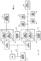
- Figs. 2 and 3 are illustrations of various system configurations for the embodiment being described. As shown in Fig. 2, a
computer 100 includes a central processing unit (CPU) 105 that communicates withsystem memory 110. The CPU also communicates onbus 112 with input/output channels oradapters other computer systems 125, tape drives 130, disk drives 135, or other input/output devices 138 such as optical disks. Thecomputer 100 may also include a compression/decompression engine 140 onbus 112. The compression/decompression engine (unit) includescompression engine 141 anddecompression engine 142. These engines may be invoked by an operating system file handler running on the CPU to do compression or decompression of data being transmitted or received through the input/output channels. The engines may utilisesystem memory 110 or anoptional memory 145 while performing the desired compression or decompression of data. Ifoptional memory 145 is used, the compressed or decompressed data may be transmitted directly to and from the I/O channels onoptional bus 147. - Fig. 3 illustrates a
computer 150 including aCPU 155 andsystem memory 160. The CPU communicates onbus 162 with input/output channels oradapters other computer systems 175, tape drives 180,disk drives 185 or other input/output devices 188. Coupled to the input/output channels are compression/decompression engines (units) 190 and 194 for compressing and decompressing some or all data passing through the input/output channels. The compression/decompression engines includecompression engines decompression engines optional memories - There are many other alternative system configurations which would be apparent to those of ordinary skill in the art. For example, one computer system, such as a server, may include a data compression engine for compressing all data sent to it while the remaining computer systems may each include a decompression engine to decompress all data they receive from the server.
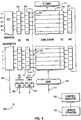
- Fig. 4 is a block diagram illustrating a preferred embodiment of
data compression engine 300. The operation of the various elements of the data compression engine are controlled by acontrol circuit 305 which is coupled to each of the elements described below. The control circuit is a logic circuit which operates as a state machine as will be described in greater detail below. Data enters the compression engine oninput data bus 310 into input data buffer register (IDBR) 320 and is later stored in a backupinput data buffer 321. The data stored in the input data buffer register is then compared with all current entries in a content addressable memory (CAM)array 330. - The CAM array includes many sections (N+1 sections are shown in the figure), each section including a register and a comparator (as will be described in greater detail in Fig. 5 below). Each CAM array register stores a word of data and includes a
single storage element 335, called an empty cell EC, for indicating whether a valid or current data word is stored in the CAM array register. Each comparator generates a match or active signal when the data word stored in the corresponding CAM array register matches the data word stored in the input data buffer register 320 (plus some other criteria described below). - Coupled to the CAM array is a write select shift register (WS) 340 with one write select cell for each section of the CAM array. At any selected time, there is a single write select cell set to 1 or active while the remaining cells are set to 0 or inactive. The active write select cell selects which section of the CAM array will be used to store the data word currently held in the input data buffer register. The write select shift register will then be shifted one cell to determine which CAM array section will store the next data word in the input data buffer register. The use of the write select shift register provides for many of the capabilities of the above described prior art Lempel-Ziv shift register while also allowing the use of fixed addresses.
- Current entries in the CAM array are designated as those CAM array sections that have empty cells (EC) set to 1 and have corresponding write select (WS) cells set to 0. If the data in any of the current CAM entries matches the data word in the input data buffer register, then the comparator for that CAM array section will generate an active match signal on its corresponding one of the match lines 342. As a result, a match OR
gate 344, which is coupled to each of the match lines, will generate a match signal. - A primary selector shift register (PS) 350 is used to indicate those corresponding sections in the CAM array where the matching operation has been successful so far. That is, a PS cell which is set to 1 (active) indicates which CAM array section contains the last word of a matching string, or sequence, of data words. More than one cell in the PS column may be active because there could be a number of sections in the CAM array where the incoming string of data words has occurred before. If the incoming stream of data words has not occurred before, then raw (uncompressed) data tokens are generated so as to contain the stream of data words until a stream of data words is found that does match previously processed data.
- Prior to loading another new data word into the input
data buffer register 320, the preceding entry in the input data buffer register is saved in backup input data buffer register (B_IDBR) 321. In addition, the contents of the column of PS cells is saved in a corresponding secondary selector (SS)register 355. Furthermore, alength counter 390 is incremented by 1 to maintain a length of the matching string. Finally, the primary selector PS and write selector WS cells are shifted one location so that the entry for the Mth PS cell is now stored in the (M+1)th PS cell and the entry for the Mth WS cell is now stored in the (M+1)th WS cell. This shift operation accomplishes two things. First, it shifts the single active write selector entry one cell so the next incoming data word is written into the next sequential section of the CAM array. Secondly, it shifts the active cells in the primary selector column so they each correspond to the CAM array sections immediately subsequent to the previous matching CAM array sections in the sequence of the array sections. - Once a new incoming data word has been loaded into the input
data buffer register 320, it is compared with all the current entries in the CAM array as described above. The corresponding match lines will be active for all CAM array data cell entries that match the new data word. If any of the match lines is active, then the match ORgate 344 will be active. All active PS cells whose corresponding match lines are not active are cleared. If any of the PS cell entries remains active, indicating that the current data word in the input data buffer register extends the previous matching string of data words, then aPS OR gate 365 coupled to all of the PS cells will be active. Therefore, the next data word can be processed to determine whether it may also continue the matching string of data words stored in the CAM array. This matching process continues until there is a 0 at the output of the PS OR gate, signifying that there are now no matches left. When this occurs, the values marking the end points of all the matching strings existing prior to this last data word are still stored in the SS cells.Address generator 370 then determines the location of one of the matching strings and generates its address onbus 380. Theaddress generator 370 may be a logic circuit utilised to generate an address given a signal from one or more of the cells of thesecondary selector register 355. Such a logic circuit may be easily designed by one of ordinary skill in the art. The length of the matching string has been tracked bylength counter 390. - The
address generator 370 generates the fixed (also known as absolute) address of the section of theCAM array 330 containing the end of the matching string and thelength counter 390 provides the length of the matching string. Therefore, a start address and length of the matching string can be calculated, encoded and generated as a token. This process is described in greater detail below. - One advantage of using a fixed address to store data words is that the data words do not need to be shifted from register to register, which could require additional circuitry. The arrangement being described uses a shifting wraparound write select cell to determine which fixed address CAM array section to write information to and utilises the features of a content addressable memory to do the many needed comparisons to find matches with previous strings of data. As a result, the arrangement being described performs compression more quickly and efficiently.
- The arrangement being described also provides for more effective compression than many existing Lempel-Ziv techniques because the search for matching data strings is exhaustive. That is, the
CAM array 330 allows for an exhaustive search for all possible matching strings. Many existing techniques use a compromising technique such as hashing in order to reduce the search time but which may not find the longest matching string in memory. - Fig. 5 is a block diagram illustrating a single section of the
compression engine 300. Thissection 500 includes a writeselect cell 510, aCAM array section 525, aprimary selector cell 550 and asecondary selector cell 560. TheCAM array section 525 includes acomparator 540 and aregister 530 which includes anempty cell 520. Each of these elements is coupled to thecontrol circuitry 305 described above. - A
reset signal line 600 is utilised by the control circuitry to clear the writeselect cell 510 and theempty cell 520 to 0 when the reset signal line is active. Ashift signal line 610 is utilised to shift the value in the writeselect cell 510 and theprimary selector cell 550 to the next CAM array section as well as to receive the value stored in the previous CAM array section. If the Mth cell is the last cell in the CAM array, then the value in the cell will be wrapped around to the first cell in the CAM array. WS IN andWS OUT lines PS OUT lines load signal line 620 is utilised to load the value from theprimary selector cell 550 to thesecondary selector cell 560. Awrite signal line 630 is utilised to initiate writing of data to the CAM array register 530 as well as to turn the empty cell 50 to a value of 1. An inputdata buffer line 640 is utilised to transfer data from the input data buffer register IDBR to the CAM array register 530 during a writing operation or to the comparator whenever a comparison is performed. - If the write selector cell is already active (set to a value of 1), a write signal to the
write selector cell 510 will cause the write select cell to generate a signal to the empty cell and the CAM array register. The empty cell will then be set to 1 and the CAM array register will have the data on the input databuffer register bus 640 written into the CAM array register. The value on the input data buffer register bus and the hard coded 1 and 0 are compared bycomparator 540 to the value inCAM array register 530, the value ofempty cell 520 and the value of writeselect cell 510. If the write select cell is set to 0 and the empty cell is set to 1 and the value on the input data buffer register bus is equal to the value in the CAM array register, then comparator 540 will generate a matched signal to the primary selector. Otherwise the comparator will generate a non-matched signal to the primary selector. - In a preferred embodiment, there are 2,048 sections in the CAM array, thereby requiring the use of at least 11 bits to designate the address of a string within the CAM array. The CAM array may be 2,048 sections connected in parallel or it may be 4 sets of 512 sections coupled in parallel. In an alternative embodiment, the CAM array is 1,024 sections deep, thereby requiring at least a 10 bit address description or 512 bits requiring at least a 9 bit address. Alternative embodiments allow the use of different size CAM arrays.
- Figs. 6A-6C is a flowchart describing the process utilised to run the
compression engine 300. In a preferred embodiment, the flowcharted process is accomplished with 21 states. The flowchart will now be described with reference to the 21 states. - In a first state 00 and
step 800, the compression engine is initialised by clearing thelength counter 390 to 0, clearing all theprimary selector cells 350, clearing all theempty cells 335 in the CAM array to 0, clearing all the writeselect cells 340 to 0 and setting the last write select cell (N) to 1. Because the empty cells are all cleared to 0, the entries in the CAM array registers do not need to be cleared, thereby saving time and decreasing power requirements. Execution then proceeds tostate 01. - In
state 01 andstep 810, if an input word is not available on theinput data bus 310 for loading into the inputdata buffer register 320, then execution will proceed tostate 15, otherwise execution will proceed tostate 02. This is to handle the "end of file" condition wherein there are no more input data words to be compressed. - In
state 02 and steps 810-860, the data word in the inputdata buffer register 320 is moved to the backup inputdata buffer register 321 and the next data word on the input data bus is read into the input data buffer register. In addition, the data in theprimary selector 350 is loaded into thesecondary selector 355 to store the results of any previous string matching operations that have occurred so far. Furthermore, the primary selector cells PS and write selector cells WS are shifted one position. The write select cells are shifted one position to designate the next CAM array cell to be written to (only a single write select cell has a value of 1). The primary selector cells are shifted one position in preparation for the next compare operation. This is to check whether the next input data word will match any of the data words in the CAM array that follow previously successful string matches. Finally, a search/write function is performed on the CAM array. This function first compares the data word in the inputdata buffer register 320 with each of the data words stored in each of the sections in the CAM array that have a corresponding empty cell set to 1 (designating that the CAM array cell contains data) and a write select cell set to 0 (designating that the cell is not the next one to be written to). If there are any matches, then the corresponding match lines are set to 1, and the corresponding primary selector cells remain at 1 if they were previously set to 1. In the case of the first input data word, there are no previously matched strings as indicated by all the primary selector cells set to 0. If any match lines or primary selector cells are set to 1, then the primary selector OR gate will generate a value of 1. Subsequently, the data word in the inputdata buffer register 320 is written to the CAM array register 330 with a corresponding write select cell equal to 1. Execution then proceeds tostate 03. - In
state 03 andstep 870, execution proceeds tostate 08 if the output of the primary selector ORgate 365 is 0, otherwise execution proceeds tostate 04. This is to determine whether a previously matched string continues to match entries in the CAM array. - In
state 04 and step 880, execution proceeds tostate 07 if the length counter is less than its maximum value; otherwise execution proceeds tostate 05. In the preferred embodiment, the maximum value is 271 due to the coding used to generate the tokens that describe the string as will be described in greater detail below. In alternative embodiments, the maximum value may be based on the maximum value the length counter can store. - In
state 05 andstep 890, a compressed word token is generated. The token has a length value equal to the length counter value minus 2. The token also has a displacement value equal to the address of the lowest set secondary selector cell (indicating the cell with the last matching word to the input data string) minus the length counter value plus 1 (indicating the address at the first matching word in the CAM array to the input data string). Execution then proceeds tostate 06. - In
state 06 and steps 900-910, theprimary selector cells 350 are set to the values of the corresponding match lines 342. This clears the previous PS values and starts the next possible matching string. In addition, thelength counter 390 is cleared to 0. Execution then proceeds tostate 07. - In
state 07 andstep 920, thelength counter 390 value is incremented by one and execution is returned tostate 01 for starting work on the next data word. -
State 08 is executed if the current data word in the inputdata buffer register 320 does not continue to match any string of data words in theCAM array 330. Instate 08 andstep 930, execution proceeds tostate 10 if thelength counter 390 value is less than two. If the length counter value is two or more, then the data word in the input data buffer register ends a previous string of matching data words. - In
state 09 andstep 940, a compressed word token is generated. As described instate 05, the compressed word token has a length value equal to thelength counter 390 value minus 2 and a displacement value or length equal to the address of the lowest setsecondary selector cell 350 minus the length counter value plus 1. Execution then proceeds tostate 10. In the alternative, execution could proceed directly tostate 14. - In
state 10 andstep 950, execution proceeds tostate 12 if the length counter value is not equal to one, otherwise execution proceeds tostate 11. - In
state 11 andstep 960, a raw word token (indicating a word has not been compressed) is generated using the data value in the backupdata buffer register 321. Execution then proceeds tostate 12. In the alternative, execution could proceed directly tostate 14. - In
state 12 andstep 970, execution proceeds tostate 14 if the output from match OR gate is equal to one; otherwise execution proceeds tostate 13. - In
state 13 and steps 980-990, a raw word token is generated using the data value on the backupdata buffer register 321. Thelength counter 390 is then cleared to 0. Execution then proceeds tostate 01. - In
state 14 and steps 994-996, theprimary selector cells 350 are set equal to the values of the corresponding match lines 342. This is to start the matching of a new string of words. In addition, thelength counter 390 is cleared to 0. Execution then proceeds tostate 01. - States 15-20 are executed if there are no more data words on the input data buffer register (see state 01). In
state 15 andstep 1000, if the length counter value is less than 2, then execution proceeds tostate 18, otherwise execution proceeds tostate 16. - In
state 16 andstep 1010, the values in theprimary selector cells 350 are loaded into thesecondary selector cells 355. Execution then proceeds tostate 17. - In
state 17 andstep 1020, a compressed word token is generated as previously shown instates state 18. In the alternative, execution could proceed directly tostate 20. - In
state 18 andstep 1030, if the length counter value is equal to 0, then execution proceeds tostate 20; otherwise execution proceeds tostate 19. - In
state 19 andstep 1040, a raw word token is generated using the data value in the backupdata buffer register 321. Execution then proceeds tostate 20. - In
state 20 andstep 1050, an end marker token is generated. - Fig. 7 is an illustration of a
preferred decompression engine 1500 to decompress data generated by the above describedcompression engine 300.Control circuitry 1510 receives the compressed data stream including raw word tokens (a data word preceded by a 0), compressed word tokens (a length of a string and a start address) and an end marker token (e.g. 13 1s in a row). - If a raw word token is received, the enclosed data word is stored in
register 1520. The contents of the register are then written to a history buffer 1530 (with the same number of sections as the CAM array used to compress the data) at the address in a write counter 1540 (initially set to 0) throughaddress multiplexer 1550. In addition, the content of theregister 1520 is also generated as an output data word. Thewrite counter 1540 is then incremented by one. If the write counter value is already at N, then it is set to 0. As a result of this operation, each data word is written to the next subsequent section in thehistory buffer 1530, thereby mirroring the CAM array used during data compression, and the data word is also generated as output. - If a compressed word token is received, the address is loaded into a
read counter 1560 and the length is loaded intotoken length counter 1570. The data in the history buffer array addressed by the read counter throughmultiplexer 1550 is then read intoregister 1520. That data word is then written back into the history buffer at the address in thewrite counter 1540 to continue the mirroring of the CAM array used to compress the data. The data word in theregister 1520 is also generated as an output data word. Thewrite counter 1540 is then incremented by one as described above. If thetoken length counter 1570 value is greater than one, then it is decremented by one, theread counter 1560 is incremented by one, and the process repeats for the next data word. This process repeats until the whole data string referred to as the compressed data string has been sequentially read from the history buffer, written back into the history buffer, and generated as output. - An optional subtract unit 1580 may be included to allow this decompression engine to decompress Lempel-Ziv compressed data that utilises relational addresses as described in Figs. 1A-1C. This subtract circuit would be used to convert the relational address to a fixed address by subtracting the value in the
write counter 1540 from the relational address. The subtract circuit could also be included but disabled when decompressing data compressed by the arrangement described above and enabled when decompressing Lempel-Ziv compressed data using relational addresses. - In the preferred embodiment, a raw word token is generated as a 0 followed by the raw (uncompressed) word. A compressed word token is passed as a 1 followed by the length of the matching string and the starting location of the matching string in the CAM array (called the displacement). A control token may also be generated which starts with eight 1's and is followed with four bits designating the control instructions. Finally, an end token is passed to designate the end of a compressed data stream. The end token is thirteen 1's in a row.
- Table 1 shows the codes used in the preferred embodiment to designate the length of a compressed data word string. This type of coding is a modified logarithmic coding wherein shorter strings utilise shorter codes and longer strings utilise longer codes. This is a useful coding technique when the frequency of shorter strings is substantially greater than the frequency of longer strings. The displacement is specified with an 11 bit value in the preferred embodiment. A shorter displacement may be used with a CAM array having fewer sections.
TABLE 1 Codes Used to Designate Compressed Word Code Field Compressed Word Length 00 2 words 01 3 words 10 00 4 words 10 01 5 words 10 10 6 words 10 11 7 words 110 000 8 words ... ... ... ... ... ... ... ... 110 111 15 words 1110 0000 16 words .... .... ... ... .... .... ... ... 1110 1111 31 words 1111 0000 0000 32 words .... .... .... ... ... .... .... .... ... ... 1111 1110 1111 271 words - In order to provide for future expansion of the arrangement described above, control instructions may be passed in the compressed data stream. These control instructions may include instructions such as "reset the history buffer", "preload the history buffer with a preferred data set", etc. In a preferred arrangement, there are two types of control instructions, long and short. Table 2 illustrates long control instructions wherein a 12 bit control field is given followed by an 11 bit control subfield. This provides for 2048 subfields for each of the four control fields for a total of 8208 possible long instructions.
TABLE 2 Long Instruction Control Fields and Subfields Long Control Field Control Subfield 1111 1111 0000 0000 0000 000 - 1111 1111 111 1111 1111 0001 0000 0000 000 - 1111 1111 111 1111 1111 0010 0000 0000 000 - 1111 1111 111 1111 1111 0011 0000 0000 000 - 1111 1111 111 - Table 3 illustrates the short control instructions. The short control instructions are only 12 bits long and are, therefore, fewer in number than the total number of long control instructions. However, the short control instructions require less time to transmit. As described above, one short control field has already been defined as an end marker. The end marker is a 1 (defining the following bits as being either a compressed data token or as a control instruction) followed by the twelve bit end marker control instruction (twelve 1s).
TABLE 3 Short Instruction Control Fields Control Field Current Function 1111 1111 0100 not defined 1111 1111 0101 not defined 1111 1111 0110 not defined .... .... .... ... ....... .... .... .... ... ....... 1111 1111 1110 not defined 1111 1111 1111 end marker
Claims (4)
- Data compression apparatus comprising
means (320) for receiving an input string of data words,
storage means (330) for storing selected data words,
comparison means (540) for comparing said input data words with said stored data words,
token generating means (370) for generating tokens representing input data words which are identical to stored data words, and
means for combining said tokens with input data words which are not identical with any stored data words to form a compressed string of data words,
characterised in that said storage means comprises means for storing input data words which are not identical to any stored data words so as to increase the number of stored data words. - Data compression apparatus as claimed in Claim 1 characterised in that said storage means comprises a plurality of storage cells each capable of storing a selected data word, and means for storing each selected data word in a respective one of said storage cells,
in that said comparison means comprises means for comparing each input data word with the data word stored in each of said cells in succession, and
in that said storage means also comprises means for storing any input data word that is not identical to any stored data word in a selected empty storage cell. - Data compression apparatus as claimed in Claim 3 characterised in that said storage cells are arranged in a sequence and said selected storage cell is the next empty cell in the sequence.
- Data compression apparatus as claimed in either Claim 2 or Claim 3 characterised in that said token generating means comprises means for generating a token for an input data word which is based on the address of the cell in said storage means in which is stored the data word identical to said input data word.
Applications Claiming Priority (2)
| Application Number | Priority Date | Filing Date | Title |
|---|---|---|---|
| US80700791A | 1991-12-13 | 1991-12-13 | |
| US807007 | 1991-12-13 |
Publications (2)
| Publication Number | Publication Date |
|---|---|
| EP0546863A2 true EP0546863A2 (en) | 1993-06-16 |
| EP0546863A3 EP0546863A3 (en) | 1994-05-25 |
Family
ID=25195360
Family Applications (1)
| Application Number | Title | Priority Date | Filing Date |
|---|---|---|---|
| EP19920311359 Withdrawn EP0546863A3 (en) | 1991-12-13 | 1992-12-11 | Data compression apparatus |
Country Status (5)
| Country | Link |
|---|---|
| US (1) | US5652878A (en) |
| EP (1) | EP0546863A3 (en) |
| JP (1) | JP3225638B2 (en) |
| BR (1) | BR9204635A (en) |
| CA (1) | CA2077271C (en) |
Cited By (6)
| Publication number | Priority date | Publication date | Assignee | Title |
|---|---|---|---|---|
| EP0633668A2 (en) * | 1993-07-08 | 1995-01-11 | International Business Machines Corporation | Data compression apparatus |
| EP0634839A1 (en) * | 1993-07-16 | 1995-01-18 | International Business Machines Corporation | Data search device |
| EP0677927A2 (en) * | 1994-04-15 | 1995-10-18 | International Business Machines Corporation | Character string pattern matching for compression and the like using minimal cycles per character |
| EP0734126A1 (en) * | 1995-03-23 | 1996-09-25 | International Business Machines Corporation | Two-stage compression with runlength encoding and lempel-ziv encoding |
| US5771011A (en) * | 1996-07-15 | 1998-06-23 | International Business Machines Corporation | Match detect logic for multi-byte per cycle hardware data compression |
| WO2000038049A1 (en) * | 1998-12-22 | 2000-06-29 | Systemonic Ag | Device and method for generating and executing compressed programs of a very long instruction word processor |
Families Citing this family (32)
| Publication number | Priority date | Publication date | Assignee | Title |
|---|---|---|---|---|
| US6002411A (en) * | 1994-11-16 | 1999-12-14 | Interactive Silicon, Inc. | Integrated video and memory controller with data processing and graphical processing capabilities |
| US7190284B1 (en) | 1994-11-16 | 2007-03-13 | Dye Thomas A | Selective lossless, lossy, or no compression of data based on address range, data type, and/or requesting agent |
| US5771010A (en) * | 1995-03-22 | 1998-06-23 | Ibm Corporation | Apparatus for compressing data using a Lempel-Ziv-type algorithm |
| JPH09265397A (en) * | 1996-03-29 | 1997-10-07 | Hitachi Ltd | Processor for vliw instruction |
| US6115787A (en) * | 1996-11-05 | 2000-09-05 | Hitachi, Ltd. | Disc storage system having cache memory which stores compressed data |
| US6879266B1 (en) | 1997-08-08 | 2005-04-12 | Quickshift, Inc. | Memory module including scalable embedded parallel data compression and decompression engines |
| US5877711A (en) * | 1997-09-19 | 1999-03-02 | International Business Machines Corporation | Method and apparatus for performing adaptive data compression |
| US5874908A (en) * | 1997-09-19 | 1999-02-23 | International Business Machines Corporation | Method and apparatus for encoding Lempel-Ziv 1 variants |
| US5874907A (en) * | 1997-09-19 | 1999-02-23 | International Business Machines Corporation | Method and apparatus for providing improved data compression efficiency for an adaptive data compressor |
| US6279016B1 (en) | 1997-09-21 | 2001-08-21 | Microsoft Corporation | Standardized filtering control techniques |
| US6008743A (en) * | 1997-11-19 | 1999-12-28 | International Business Machines Corporation | Method and apparatus for switching between data compression modes |
| US6216175B1 (en) | 1998-06-08 | 2001-04-10 | Microsoft Corporation | Method for upgrading copies of an original file with same update data after normalizing differences between copies created during respective original installations |
| US6218970B1 (en) * | 1998-09-11 | 2001-04-17 | International Business Machines Corporation | Literal handling in LZ compression employing MRU/LRU encoding |
| US20010054131A1 (en) * | 1999-01-29 | 2001-12-20 | Alvarez Manuel J. | System and method for perfoming scalable embedded parallel data compression |
| US7129860B2 (en) * | 1999-01-29 | 2006-10-31 | Quickshift, Inc. | System and method for performing scalable embedded parallel data decompression |
| US6208273B1 (en) * | 1999-01-29 | 2001-03-27 | Interactive Silicon, Inc. | System and method for performing scalable embedded parallel data compression |
| US6822589B1 (en) | 1999-01-29 | 2004-11-23 | Quickshift, Inc. | System and method for performing scalable embedded parallel data decompression |
| US6466999B1 (en) | 1999-03-31 | 2002-10-15 | Microsoft Corporation | Preprocessing a reference data stream for patch generation and compression |
| JP2001084707A (en) * | 1999-09-10 | 2001-03-30 | Toshiba Corp | Method and apparatus for decoding of variable-length code and computer-readable recording medium with decoding program of variable-length code recorded therein |
| US6615310B1 (en) | 2000-05-18 | 2003-09-02 | International Business Machines Corporation | Lossless data compressor with all CAM words available |
| US6404356B1 (en) * | 2000-05-22 | 2002-06-11 | Cennoid Technologies, Inc. | Wave demodulation processor |
| US20030217025A1 (en) * | 2000-09-11 | 2003-11-20 | David Costantino | Textual data storage system and method |
| US6771193B2 (en) | 2002-08-22 | 2004-08-03 | International Business Machines Corporation | System and methods for embedding additional data in compressed data streams |
| US7373454B1 (en) * | 2003-10-28 | 2008-05-13 | Altera Corporation | Pattern detect and byte align circuit using CAM |
| JP2006295853A (en) * | 2005-04-14 | 2006-10-26 | Sony Corp | Coding apparatus, decoding apparatus, coding method and decoding method |
| US7180433B1 (en) | 2005-09-22 | 2007-02-20 | Tandberg Storage Asa | Fast data compression and decompression system and method |
| JP4940824B2 (en) * | 2006-08-18 | 2012-05-30 | 富士通セミコンダクター株式会社 | Nonvolatile semiconductor memory |
| NZ549548A (en) * | 2006-08-31 | 2009-04-30 | Arc Innovations Ltd | Managing supply of a utility to a customer premises |
| IL205528A (en) * | 2009-05-04 | 2014-02-27 | Storwize Ltd | Method and system for compression of logical data objects for storage |
| US8013762B2 (en) * | 2009-11-03 | 2011-09-06 | Seagate Technology Llc | Evaluating alternative encoding solutions during data compression |
| US20120033239A1 (en) * | 2010-08-05 | 2012-02-09 | John Thomas Varga | Mechanism for Inserting Information Into a Bitmap |
| WO2015029224A1 (en) * | 2013-08-30 | 2015-03-05 | 富士通株式会社 | Data compression device, method, and program |
Citations (1)
| Publication number | Priority date | Publication date | Assignee | Title |
|---|---|---|---|---|
| EP0380294A1 (en) * | 1989-01-23 | 1990-08-01 | Codex Corporation | String matching |
Family Cites Families (51)
| Publication number | Priority date | Publication date | Assignee | Title |
|---|---|---|---|---|
| US3914586A (en) * | 1973-10-25 | 1975-10-21 | Gen Motors Corp | Data compression method and apparatus |
| US4021782A (en) * | 1974-01-07 | 1977-05-03 | Hoerning John S | Data compaction system and apparatus |
| US4054951A (en) * | 1976-06-30 | 1977-10-18 | International Business Machines Corporation | Data expansion apparatus |
| US4087788A (en) * | 1977-01-14 | 1978-05-02 | Ncr Canada Ltd - Ncr Canada Ltee | Data compression system |
| US4463342A (en) * | 1979-06-14 | 1984-07-31 | International Business Machines Corporation | Method and means for carry-over control in the high order to low order pairwise combining of digits of a decodable set of relatively shifted finite number strings |
| US4286256A (en) * | 1979-11-28 | 1981-08-25 | International Business Machines Corporation | Method and means for arithmetic coding utilizing a reduced number of operations |
| US4295125A (en) * | 1980-04-28 | 1981-10-13 | International Business Machines Corporation | Method and means for pipeline decoding of the high to low order pairwise combined digits of a decodable set of relatively shifted finite number of strings |
| US4467317A (en) * | 1981-03-30 | 1984-08-21 | International Business Machines Corporation | High-speed arithmetic compression coding using concurrent value updating |
| US4464650A (en) * | 1981-08-10 | 1984-08-07 | Sperry Corporation | Apparatus and method for compressing data signals and restoring the compressed data signals |
| US4560976A (en) * | 1981-10-15 | 1985-12-24 | Codex Corporation | Data compression |
| US4622545A (en) * | 1982-09-30 | 1986-11-11 | Apple Computer, Inc. | Method and apparatus for image compression and manipulation |
| NL8301264A (en) * | 1983-04-11 | 1984-11-01 | Philips Nv | REGULAR COMPRESSION DEVICE FOR COMPRESSING BINARY DATA OF AN IMAGE AND SCAN DEVICE FOR A DOCUMENT PROVIDED FOR COMPRESSING SUCH. |
| US4677649A (en) * | 1983-04-26 | 1987-06-30 | Canon Kabushiki Kaisha | Data receiving apparatus |
| US4814746A (en) * | 1983-06-01 | 1989-03-21 | International Business Machines Corporation | Data compression method |
| US4558302A (en) * | 1983-06-20 | 1985-12-10 | Sperry Corporation | High speed data compression and decompression apparatus and method |
| JPH0828053B2 (en) * | 1983-08-08 | 1996-03-21 | 株式会社日立製作所 | Data recording method |
| US4633490A (en) * | 1984-03-15 | 1986-12-30 | International Business Machines Corporation | Symmetrical optimized adaptive data compression/transfer/decompression system |
| US4612532A (en) * | 1984-06-19 | 1986-09-16 | Telebyte Corportion | Data compression apparatus and method |
| GB2172127B (en) * | 1985-03-06 | 1988-10-12 | Ferranti Plc | Data compression system |
| US4682150A (en) * | 1985-12-09 | 1987-07-21 | Ncr Corporation | Data compression method and apparatus |
| US4652856A (en) * | 1986-02-04 | 1987-03-24 | International Business Machines Corporation | Multiplication-free multi-alphabet arithmetic code |
| US4935882A (en) * | 1986-09-15 | 1990-06-19 | International Business Machines Corporation | Probability adaptation for arithmetic coders |
| US4905297A (en) * | 1986-09-15 | 1990-02-27 | International Business Machines Corporation | Arithmetic coding encoder and decoder system |
| US4891643A (en) * | 1986-09-15 | 1990-01-02 | International Business Machines Corporation | Arithmetic coding data compression/de-compression by selectively employed, diverse arithmetic coding encoders and decoders |
| US4730348A (en) * | 1986-09-19 | 1988-03-08 | Adaptive Computer Technologies | Adaptive data compression system |
| JPH0815263B2 (en) * | 1986-12-12 | 1996-02-14 | 株式会社日立製作所 | Data compression / decompression method |
| US4853696A (en) * | 1987-04-13 | 1989-08-01 | University Of Central Florida | Code converter for data compression/decompression |
| US4943869A (en) * | 1987-05-06 | 1990-07-24 | Fuji Photo Film Co., Ltd. | Compression method for dot image data |
| US4876541A (en) * | 1987-10-15 | 1989-10-24 | Data Compression Corporation | Stem for dynamically compressing and decompressing electronic data |
| US4891784A (en) * | 1988-01-08 | 1990-01-02 | Hewlett-Packard Company | High capacity tape drive transparently writes and reads large packets of blocked data between interblock gaps |
| US4906991A (en) * | 1988-04-29 | 1990-03-06 | Xerox Corporation | Textual substitution data compression with finite length search windows |
| US4899147A (en) * | 1988-06-03 | 1990-02-06 | Unisys Corporation | Data compression/decompression apparatus with throttle, start-up and backward read controls |
| JPH0222732A (en) * | 1988-07-11 | 1990-01-25 | Fujitsu Ltd | Data compressing device |
| US5016009A (en) * | 1989-01-13 | 1991-05-14 | Stac, Inc. | Data compression apparatus and method |
| US5003307A (en) * | 1989-01-13 | 1991-03-26 | Stac, Inc. | Data compression apparatus with shift register search means |
| US5025258A (en) * | 1989-06-01 | 1991-06-18 | At&T Bell Laboratories | Adaptive probability estimator for entropy encoding/decoding |
| US5023611A (en) * | 1989-07-28 | 1991-06-11 | At&T Bell Laboratories | Entropy encoder/decoder including a context extractor |
| JP2940948B2 (en) * | 1989-08-22 | 1999-08-25 | 富士通株式会社 | Data compression method |
| US4988998A (en) * | 1989-09-05 | 1991-01-29 | Storage Technology Corporation | Data compression system for successively applying at least two data compression methods to an input data stream |
| US5109433A (en) * | 1989-10-13 | 1992-04-28 | Microsoft Corporation | Compressing and decompressing text files |
| US4955066A (en) * | 1989-10-13 | 1990-09-04 | Microsoft Corporation | Compressing and decompressing text files |
| US5001478A (en) * | 1989-12-28 | 1991-03-19 | International Business Machines Corporation | Method of encoding compressed data |
| US5130993A (en) * | 1989-12-29 | 1992-07-14 | Codex Corporation | Transmitting encoded data on unreliable networks |
| US4973961A (en) * | 1990-02-12 | 1990-11-27 | At&T Bell Laboratories | Method and apparatus for carry-over control in arithmetic entropy coding |
| JPH0834434B2 (en) * | 1990-02-26 | 1996-03-29 | 三菱電機株式会社 | Encoding device and encoding method |
| US5049881A (en) * | 1990-06-18 | 1991-09-17 | Intersecting Concepts, Inc. | Apparatus and method for very high data rate-compression incorporating lossless data compression and expansion utilizing a hashing technique |
| US5051745A (en) * | 1990-08-21 | 1991-09-24 | Pkware, Inc. | String searcher, and compressor using same |
| CA2065578C (en) * | 1991-04-22 | 1999-02-23 | David W. Carr | Packet-based data compression method |
| US5245614A (en) * | 1991-04-29 | 1993-09-14 | Codex Corporation | Vocabulary memory allocation for adaptive data compression of frame-multiplexed traffic |
| US5140321A (en) * | 1991-09-04 | 1992-08-18 | Prime Computer, Inc. | Data compression/decompression method and apparatus |
| US5155484A (en) * | 1991-09-13 | 1992-10-13 | Salient Software, Inc. | Fast data compressor with direct lookup table indexing into history buffer |
-
1992
- 1992-09-01 CA CA002077271A patent/CA2077271C/en not_active Expired - Fee Related
- 1992-11-16 JP JP30510692A patent/JP3225638B2/en not_active Expired - Fee Related
- 1992-12-01 BR BR9204635A patent/BR9204635A/en active Search and Examination
- 1992-12-11 EP EP19920311359 patent/EP0546863A3/en not_active Withdrawn
-
1995
- 1995-10-02 US US08/537,569 patent/US5652878A/en not_active Expired - Lifetime
Patent Citations (1)
| Publication number | Priority date | Publication date | Assignee | Title |
|---|---|---|---|---|
| EP0380294A1 (en) * | 1989-01-23 | 1990-08-01 | Codex Corporation | String matching |
Cited By (9)
| Publication number | Priority date | Publication date | Assignee | Title |
|---|---|---|---|---|
| EP0633668A2 (en) * | 1993-07-08 | 1995-01-11 | International Business Machines Corporation | Data compression apparatus |
| EP0633668A3 (en) * | 1993-07-08 | 1996-01-31 | Ibm | Data compression apparatus. |
| EP0634839A1 (en) * | 1993-07-16 | 1995-01-18 | International Business Machines Corporation | Data search device |
| EP0677927A2 (en) * | 1994-04-15 | 1995-10-18 | International Business Machines Corporation | Character string pattern matching for compression and the like using minimal cycles per character |
| EP0677927A3 (en) * | 1994-04-15 | 1997-06-11 | Ibm | Character string pattern matching for compression and the like using minimal cycles per character. |
| EP0734126A1 (en) * | 1995-03-23 | 1996-09-25 | International Business Machines Corporation | Two-stage compression with runlength encoding and lempel-ziv encoding |
| US5627534A (en) * | 1995-03-23 | 1997-05-06 | International Business Machines Corporation | Dual stage compression of bit mapped image data using refined run length and LZ compression |
| US5771011A (en) * | 1996-07-15 | 1998-06-23 | International Business Machines Corporation | Match detect logic for multi-byte per cycle hardware data compression |
| WO2000038049A1 (en) * | 1998-12-22 | 2000-06-29 | Systemonic Ag | Device and method for generating and executing compressed programs of a very long instruction word processor |
Also Published As
| Publication number | Publication date |
|---|---|
| JPH05233212A (en) | 1993-09-10 |
| JP3225638B2 (en) | 2001-11-05 |
| BR9204635A (en) | 1993-06-15 |
| CA2077271C (en) | 1998-07-28 |
| CA2077271A1 (en) | 1993-06-14 |
| EP0546863A3 (en) | 1994-05-25 |
| US5652878A (en) | 1997-07-29 |
Similar Documents
| Publication | Publication Date | Title |
|---|---|---|
| EP0546863A2 (en) | Data compression apparatus | |
| US5563595A (en) | Method and apparatus for compressing data | |
| EP0129439B1 (en) | High speed data compression and decompression apparatus and method | |
| US5179378A (en) | Method and apparatus for the compression and decompression of data using Lempel-Ziv based techniques | |
| US5281967A (en) | Data compression/decompression method and apparatus | |
| EP0666651B1 (en) | Apparatus and method for lempel ziv data compression with management of multiple dictionaries in content addressable memory | |
| US5572206A (en) | Data compression method and system | |
| US5373290A (en) | Apparatus and method for managing multiple dictionaries in content addressable memory based data compression | |
| US5339398A (en) | Memory architecture and method of data organization optimized for hashing | |
| US6563956B1 (en) | Method and apparatus for compressing data string | |
| US5572209A (en) | Method and apparatus for compressing and decompressing data | |
| US5113516A (en) | Data repacker having controlled feedback shifters and registers for changing data format | |
| US5175543A (en) | Dictionary reset performance enhancement for data compression applications | |
| JPH08274649A (en) | Data compression equipment using lempel-ziv type algorithm | |
| JPH05276052A (en) | Method for decoding huffman code word and device therefor | |
| US6507877B1 (en) | Asynchronous concurrent dual-stream FIFO | |
| US5058137A (en) | Lempel-Ziv decoder | |
| US5262776A (en) | Process for use with lempel/gin encoding | |
| EP0411691B1 (en) | Memory architecture and circuit for hashing | |
| Henriques et al. | A parallel architecture for data compression | |
| JP3038234B2 (en) | Dictionary search method for data compression equipment | |
| EP0411692B1 (en) | Lempel-Ziv decoder | |
| EP1323122A2 (en) | Index relational processor |
Legal Events
| Date | Code | Title | Description |
|---|---|---|---|
| PUAI | Public reference made under article 153(3) epc to a published international application that has entered the european phase |
Free format text: ORIGINAL CODE: 0009012 |
|
| AK | Designated contracting states |
Kind code of ref document: A2 Designated state(s): CH DE FR GB IT LI NL SE |
|
| 17P | Request for examination filed |
Effective date: 19931021 |
|
| PUAL | Search report despatched |
Free format text: ORIGINAL CODE: 0009013 |
|
| AK | Designated contracting states |
Kind code of ref document: A3 Designated state(s): CH DE FR GB IT LI NL SE |
|
| 17Q | First examination report despatched |
Effective date: 19951228 |
|
| GRAG | Despatch of communication of intention to grant |
Free format text: ORIGINAL CODE: EPIDOS AGRA |
|
| GRAG | Despatch of communication of intention to grant |
Free format text: ORIGINAL CODE: EPIDOS AGRA |
|
| GRAH | Despatch of communication of intention to grant a patent |
Free format text: ORIGINAL CODE: EPIDOS IGRA |
|
| GRAH | Despatch of communication of intention to grant a patent |
Free format text: ORIGINAL CODE: EPIDOS IGRA |
|
| STAA | Information on the status of an ep patent application or granted ep patent |
Free format text: STATUS: THE APPLICATION IS DEEMED TO BE WITHDRAWN |
|
| 18D | Application deemed to be withdrawn |
Effective date: 19980701 |