EP0546207A1 - Card lock and a punchable key card - Google Patents
Card lock and a punchable key card Download PDFInfo
- Publication number
- EP0546207A1 EP0546207A1 EP19910121164 EP91121164A EP0546207A1 EP 0546207 A1 EP0546207 A1 EP 0546207A1 EP 19910121164 EP19910121164 EP 19910121164 EP 91121164 A EP91121164 A EP 91121164A EP 0546207 A1 EP0546207 A1 EP 0546207A1
- Authority
- EP
- European Patent Office
- Prior art keywords
- card
- lock
- dead bolt
- holes
- pin tumblers
- Prior art date
- Legal status (The legal status is an assumption and is not a legal conclusion. Google has not performed a legal analysis and makes no representation as to the accuracy of the status listed.)
- Withdrawn
Links
Images


Classifications
-
- E—FIXED CONSTRUCTIONS
- E05—LOCKS; KEYS; WINDOW OR DOOR FITTINGS; SAFES
- E05B—LOCKS; ACCESSORIES THEREFOR; HANDCUFFS
- E05B35/00—Locks for use with special keys or a plurality of keys ; keys therefor
- E05B35/007—Locks for use with special keys or a plurality of keys ; keys therefor the key being a card, e.g. perforated, or the like
-
- Y—GENERAL TAGGING OF NEW TECHNOLOGICAL DEVELOPMENTS; GENERAL TAGGING OF CROSS-SECTIONAL TECHNOLOGIES SPANNING OVER SEVERAL SECTIONS OF THE IPC; TECHNICAL SUBJECTS COVERED BY FORMER USPC CROSS-REFERENCE ART COLLECTIONS [XRACs] AND DIGESTS
- Y10—TECHNICAL SUBJECTS COVERED BY FORMER USPC
- Y10T—TECHNICAL SUBJECTS COVERED BY FORMER US CLASSIFICATION
- Y10T70/00—Locks
- Y10T70/70—Operating mechanism
- Y10T70/7051—Using a powered device [e.g., motor]
- Y10T70/7057—Permanent magnet
-
- Y—GENERAL TAGGING OF NEW TECHNOLOGICAL DEVELOPMENTS; GENERAL TAGGING OF CROSS-SECTIONAL TECHNOLOGIES SPANNING OVER SEVERAL SECTIONS OF THE IPC; TECHNICAL SUBJECTS COVERED BY FORMER USPC CROSS-REFERENCE ART COLLECTIONS [XRACs] AND DIGESTS
- Y10—TECHNICAL SUBJECTS COVERED BY FORMER USPC
- Y10T—TECHNICAL SUBJECTS COVERED BY FORMER US CLASSIFICATION
- Y10T70/00—Locks
- Y10T70/70—Operating mechanism
- Y10T70/7441—Key
- Y10T70/7486—Single key
- Y10T70/7508—Tumbler type
- Y10T70/752—Sliding tumblers
- Y10T70/7531—Transverse
-
- Y—GENERAL TAGGING OF NEW TECHNOLOGICAL DEVELOPMENTS; GENERAL TAGGING OF CROSS-SECTIONAL TECHNOLOGIES SPANNING OVER SEVERAL SECTIONS OF THE IPC; TECHNICAL SUBJECTS COVERED BY FORMER USPC CROSS-REFERENCE ART COLLECTIONS [XRACs] AND DIGESTS
- Y10—TECHNICAL SUBJECTS COVERED BY FORMER USPC
- Y10T—TECHNICAL SUBJECTS COVERED BY FORMER US CLASSIFICATION
- Y10T70/00—Locks
- Y10T70/70—Operating mechanism
- Y10T70/7441—Key
- Y10T70/7486—Single key
- Y10T70/7508—Tumbler type
- Y10T70/7559—Cylinder type
- Y10T70/7582—Sliding plug
-
- Y—GENERAL TAGGING OF NEW TECHNOLOGICAL DEVELOPMENTS; GENERAL TAGGING OF CROSS-SECTIONAL TECHNOLOGIES SPANNING OVER SEVERAL SECTIONS OF THE IPC; TECHNICAL SUBJECTS COVERED BY FORMER USPC CROSS-REFERENCE ART COLLECTIONS [XRACs] AND DIGESTS
- Y10—TECHNICAL SUBJECTS COVERED BY FORMER USPC
- Y10T—TECHNICAL SUBJECTS COVERED BY FORMER US CLASSIFICATION
- Y10T70/00—Locks
- Y10T70/70—Operating mechanism
- Y10T70/7441—Key
- Y10T70/7757—Push or pull key operation
-
- Y—GENERAL TAGGING OF NEW TECHNOLOGICAL DEVELOPMENTS; GENERAL TAGGING OF CROSS-SECTIONAL TECHNOLOGIES SPANNING OVER SEVERAL SECTIONS OF THE IPC; TECHNICAL SUBJECTS COVERED BY FORMER USPC CROSS-REFERENCE ART COLLECTIONS [XRACs] AND DIGESTS
- Y10—TECHNICAL SUBJECTS COVERED BY FORMER USPC
- Y10T—TECHNICAL SUBJECTS COVERED BY FORMER US CLASSIFICATION
- Y10T70/00—Locks
- Y10T70/70—Operating mechanism
- Y10T70/7441—Key
- Y10T70/778—Operating elements
- Y10T70/7791—Keys
- Y10T70/7842—Single shank or stem
- Y10T70/7859—Flat rigid
Definitions
- Any sort of locks for anti-theft such as, a door lock, an automobile steering lock, a motorcycle lock, a cabinet lock, a drawer lock, a padlock, etc. should have a locking mechanism and a key to unlock the lock mechanism. And pin tumblers are most widely used as the lock mechanism.
- This invention has been devised to supply a sort of card lock without using electric power for unlocking with a key card having a plurality of through holes to be easily carried with a user just as a common credit.
- the card lock and the key card in the present invention has been planned to have the following advantages.
- the key card in the present invention as shown in Figs. 1 - 6 has a special pre-set arrangement of through holes 10 punched out of it to coordinate to the numbers and the locations of long pin tumblers 20 provided in a card lock 2, but no holes are punched at the locations coordinating to short pin tumblers in the card lock. So the ends of the long pin tumblers 20 can fall to fit in the through holes 10 and the ends of the short pin tumblers 20 are pushed up to rest on the surface of the key card 1 when the key card 1 is inserted in a card slot in the card lock 2 to unlock it.
- the key card 1 can be made as a main card made of non-magnetic, non-powered and non-ferreous material to be reserved for copying an auxiliary one for daily use by a person, and the auxiliary card is also made of the same material as the main one like a common credit card. So the key card has no projection on both surfaces, very convenient to carry in a pocket or a wallet.
- Figs. 7, 8, 9 show the card locks 2 respectively coordinating to the key cards 1 shown in Figs. 1, 3, 5, and the card lock 2 have pin tumblers 20 long and short in a planned locations in 3 or 4 rows of a plurality, for example 6, of pin tumblers in each row. And the coordinating key card 1 has through holes 10 arranged in the same location and number of the long pin tumblers 20 only.
- the card lock 2 shown in Fig. 10 has pin tumblers 20 with magnetism without a powered mechanism, and that shown in Fig. 11 has pin tumblers 20 without magnetism or a powered mechanism.
- the pin tumblers 20 are to be returned to their original position (the locked position) from the unlocked position by means of magnetic force in one kind, and by means of resiliency of springs in another kind.
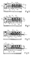
- the card lock 2 having magnetic means shown in Fig. 10 is provided with the same polar magnets 4 buried in the inner lower lengthwise wall and pin tumbler holes 21 in the opposite inner upper lengthwise wall for receiving the pin tumblers 20.
- a dead bolt mover 5 is provided to fit movably in the lengthwise cavity between both the upper and the lower wall, having the same number of crosswise through holes 50 as the pin tumbler holes 21 for the pin tumblers 20 long and short to fit therein.
- the upper ends of the pin tumblers 20 have the opposite polar magnetism to the magnets 4 and magnets 6 are placed on the upper ends of the pin tumblers 20 and extend in the pin tumbler holes 21 so as to attract the ends of the pin tumblers 20.
- the pin tumblers 20 are attracted by the magnets 4 so that the locking magnets 6 on the ends of the pin tumblers 20 may go down to be located partly in the pin tumbler holes 21 and partly in the through holes 50 in the dead bolt mover 5 and consequently the dead bolt mover 5 is kept immovable, with its front end sticking in and stopping the dead bolt in the locked position as shown in Fig. 10.
- Fig. 12 shows the unlocked condition of the card lock 2 shown in Fig. 10 with the key card 1 inserted in the card slot 3.
- the key card 1 is punched to have through holes 10 arranged just as in the same locations as the long pin tumblers 20 in the card lock 2.
- the long pin tumblers 20 may fit in the corresponding through holes 20 and the short pin tumblers 20 may be pushed up to sit on the surface of the card 1 so that the upper edges of the long and short pin tumblers 20 and the upper surface of the dead bolt mover can aligh in a straight line.
- dead bolt mover 5 with the pin tumblers 20 in its holes 50 can be pushed further inward by the card 1 to the unlocked position and the inclined front end of the dead bolt mover 5 can force the dead bolt to retreat to unlock this lock.
- the length of each short tumbler is as long as the thickness of the dead bolt mover 5 and that of each long pin tumbler is as long as the thickness of the dead bolt mover 5 plus the thickness of the card 1.
- FIG. 11 Another example of the card lock in the present invention shown in Fig. 11, has the pin tumblers 20 of non-magnetism and no magnets 4 in the lower wall as the first example, but upper pin tumblers 60 and lower pin tumblers 20 and springs 7 on the upper pin tumblers 60 in he pin tumbler holes 21. Then the springs 7 has resilience to function like the magnets 4 in the first example to attract the pin tumblers 20.
- Fig. 13 shows the movement of the pin tumblers 20, 60, the springs 7 and the dead bolt mover 5 when the card 1 is inserted in the slot 3 in the similar movement shown in Fig. 12.
Abstract
The invention relates to a card lock and a punchable key card comprising a key card having through holes in the coordinating locations to and the same number as long pin tumblers (20) provided in a card lock (2) for unlocking the lock (2) without electric power, the card lock (2) having a plurality of pin tumblers (20) - some long and some short mixed regularly or irregularly - and a dead bolt mover (5) having through holes (50) for the pin tumblers (20) to fit and move therein, said key card being able to push up the short pin tumblers (20) to bring the upper ends of all the pin tumblers (20) to the same level as the upper surface of the dead bolt mover (5) so that the dead bolt mover (5) can be pushed further inwards from the locked position to the unlocked position by the key card to retract the dead bolt and unlock the card lock.
Description
- Any sort of locks for anti-theft such as, a door lock, an automobile steering lock, a motorcycle lock, a cabinet lock, a drawer lock, a padlock, etc. should have a locking mechanism and a key to unlock the lock mechanism. And pin tumblers are most widely used as the lock mechanism.
- In order to make a locking mechanism more difficuly to be illegally unlocked, the number of pin tumblers in a lock are often increased. And the pin tumblers are mostly arranged in a straight line to economize the space available, no matter how many pin tumblers might be used. And a key hole is always needed in spite of the method the pin tumblers are arranged in, and any lock wherein the pin tumblers are provided in a straight line can have almost the same potentiality of being pricked open illegally, only different in difficulty. The more the pin tumblers may be provided in a lock, the larger the size of the lock would be.
- This invention has been devised to supply a sort of card lock without using electric power for unlocking with a key card having a plurality of through holes to be easily carried with a user just as a common credit. And the card lock and the key card in the present invention has been planned to have the following advantages.
-
- 1. The key for unlocking is a very thin card of non-magnetism, non-powered just as a common credit card, very convenient to carry with.
- 2. The key card can have a main one for reserve and an auxiliary one copied easily from the main one for carrying with for daily use and able to be easily copied from the main one with a carving knife in case of missing.
- 3. The key card has no magnetism, no power source but long service life.
- 4. Arrangement and preparation of through holes in the key card and long and short pin tumblers in the card lock needs no power source, and its anti-theft effectiveness is perfect.
- 5. The punchable holes in the card and the pin tumblers in the card lock can be arranged in 3 or 4 lateral rows, each row having a plurality of holes, for example 6 holes, then 18 holes in total and 18 pin tumblers. And then a large numbers of combinations of the long pin tumblers and the short ones can be planned and provided and the through holes in the key card can be bored coordinating to the locations and the same number of the long pin tumblers. And their location arrangement can be any of a triangular, curved, symemtrical or unsymmetrical, regular or irregular, planar geometrical shapes, to resultant perfect anti-theft safety.
- 6. The card slot in the card lock exposing outside is of a straight linear planar shape so that a wire or prick-open tools cannot reach in, and in addition, the pin tumblers are provided dispersed in a planer surface and perpendicular to the slot, different from a horizontal linear hole in a conventional lock, almost impossible to prick the short pin tumbers irregularly located all aligned to be illegally opened.
- 7. The key card is thin and through holes control the pin tumblers, quite different from common flat keys and rok-shaped locks, and the card lock is not funtioned by electric power.
- 8. The pin tumblers can be arranged in 3 rows with magnets or two rows with springs, located vertical to the slot, without using electric power so that problems caused by power failure or short curcuit never happens to this lock.
- 9. Unlocking of the card lock is performed by pushing the key card in the slot in the card lock, very simple.
- 10. It can widely applied to a door lock, a padlock, an automobile steering lock, a cabinet lock, a drawer lock, etc, etc.
-
- Figure 1 is a planar view of the first example of the punchable key card in the present invention.
- Figure 2 is a cross-sectional view of 2 - 2 line in Fig.1.
- Figure 3 is a planar view of the second example of the punchable key card in the present invention.
- Figure 4 is a cross-sectional view of 4 - 4 line in Fig. 3.
- Figure 5 is a planar view of the third example of the punchable key card in the present invention.
- Figure 6 is a cross-sectional view of the punchable key card in the present invention.
- Figure 7 is a planar view of the card lock coordinating to the first example of the key card shown in Fig. 1.
- Figure 8 is a planar view of the card lock coordinating to the second example of the key card shown in Fig. 3.
- Figure 9 is a planar view of the card lock coordinating to the third example of the key card shown in Fig. 5.
- Figure 10 is a cross-sectional view of the card lock in the locked position in the present invention.
- Figure 11 is another cross-sectional view of the card lock in the locked position in the present invention.
- Figure 12 is a cross-sectional view of the card lock in the unlocked position in the present invention.
- Figure 13 is another cross-sectional view of the card lock in the unlocked position in the present invention.
- The key card in the present invention, as shown in Figs. 1 - 6 has a special pre-set arrangement of through
holes 10 punched out of it to coordinate to the numbers and the locations oflong pin tumblers 20 provided in acard lock 2, but no holes are punched at the locations coordinating to short pin tumblers in the card lock. So the ends of thelong pin tumblers 20 can fall to fit in the throughholes 10 and the ends of theshort pin tumblers 20 are pushed up to rest on the surface of the key card 1 when the key card 1 is inserted in a card slot in thecard lock 2 to unlock it. - The key card 1 can be made as a main card made of non-magnetic, non-powered and non-ferreous material to be reserved for copying an auxiliary one for daily use by a person, and the auxiliary card is also made of the same material as the main one like a common credit card. So the key card has no projection on both surfaces, very convenient to carry in a pocket or a wallet.
- Figs. 7, 8, 9 show the
card locks 2 respectively coordinating to the key cards 1 shown in Figs. 1, 3, 5, and thecard lock 2 havepin tumblers 20 long and short in a planned locations in 3 or 4 rows of a plurality, for example 6, of pin tumblers in each row. And the coordinating key card 1 has throughholes 10 arranged in the same location and number of thelong pin tumblers 20 only. Thecard lock 2 shown in Fig. 10 haspin tumblers 20 with magnetism without a powered mechanism, and that shown in Fig. 11 haspin tumblers 20 without magnetism or a powered mechanism. In other words, thepin tumblers 20 are to be returned to their original position (the locked position) from the unlocked position by means of magnetic force in one kind, and by means of resiliency of springs in another kind. These two kinds of card locks have almost the same effectiveness in the function and action. Thecard lock 2 having magnetic means shown in Fig. 10 is provided with the samepolar magnets 4 buried in the inner lower lengthwise wall andpin tumbler holes 21 in the opposite inner upper lengthwise wall for receiving thepin tumblers 20. - A
dead bolt mover 5 is provided to fit movably in the lengthwise cavity between both the upper and the lower wall, having the same number of crosswise throughholes 50 as thepin tumbler holes 21 for thepin tumblers 20 long and short to fit therein. The upper ends of thepin tumblers 20 have the opposite polar magnetism to themagnets 4 andmagnets 6 are placed on the upper ends of thepin tumblers 20 and extend in thepin tumbler holes 21 so as to attract the ends of thepin tumblers 20. In the locked position thepin tumblers 20 are attracted by themagnets 4 so that thelocking magnets 6 on the ends of thepin tumblers 20 may go down to be located partly in thepin tumbler holes 21 and partly in the throughholes 50 in thedead bolt mover 5 and consequently thedead bolt mover 5 is kept immovable, with its front end sticking in and stopping the dead bolt in the locked position as shown in Fig. 10. - Fig. 12 shows the unlocked condition of the
card lock 2 shown in Fig. 10 with the key card 1 inserted in thecard slot 3. The key card 1 is punched to have throughholes 10 arranged just as in the same locations as thelong pin tumblers 20 in thecard lock 2. When the front edge of the key card 1 has been pushed to come to contact with arecess edge 51 of the dead bolt mover 5 in inserting the card 1 in thecard slot 3, thelong pin tumblers 20 may fit in the corresponding throughholes 20 and theshort pin tumblers 20 may be pushed up to sit on the surface of the card 1 so that the upper edges of the long andshort pin tumblers 20 and the upper surface of the dead bolt mover can aligh in a straight line. Then dead bolt mover 5 with thepin tumblers 20 in itsholes 50 can be pushed further inward by the card 1 to the unlocked position and the inclined front end of thedead bolt mover 5 can force the dead bolt to retreat to unlock this lock. The length of each short tumbler is as long as the thickness of the dead bolt mover 5 and that of each long pin tumbler is as long as the thickness of the dead bolt mover 5 plus the thickness of the card 1. - Another example of the card lock in the present invention shown in Fig. 11, has the
pin tumblers 20 of non-magnetism and nomagnets 4 in the lower wall as the first example, butupper pin tumblers 60 andlower pin tumblers 20 and springs 7 on theupper pin tumblers 60 in he pin tumbler holes 21. Then thesprings 7 has resilience to function like themagnets 4 in the first example to attract thepin tumblers 20. Fig. 13 shows the movement of thepin tumblers springs 7 and thedead bolt mover 5 when the card 1 is inserted in theslot 3 in the similar movement shown in Fig. 12.
Claims (12)
1. A card lock and a punchable key card comprising:
said key card being able to be inserted in the card slot in the card lock to push the dead bolt mover from the locked position to the unlocked position, in said locked position the short pin tumblers positioned partly in the pin tumbler holes in the upper wall and partly in those in the dead bolt mover so that the dead bolt mover is kept immovable, permitting the dead bolt extend out to lock the lock, in said unlocked position the short pin tumblers being pushed up by the card but the long pin tumblers fitting in the through holes in the key card so that all the long and short pin tumblers have their upper edges in the same level with the upper face of the dead bolt mover so that the dead bolt mover with the long and short pin tumblers together can be further pushed inware (forward) by the card to move the dead bolt to retreat to unlock this lock.
(a) a punchable key card having a proper thickness and being able to be inserted in a card slot in a card lock to unlock it, having through holes punched in positions coordinating to the positions of the long pin tumblers provided in the card lock;
(b) a card lock being not operated by electric power and having a card slot between an inner lower lengthwise wall and the lower lengthwise surface of a dead bolt mover positioned in a lengthwise cavity between the inner lower lengthwise wall and the inner upper lengthwise wall, a plurality of parallel pin tumbler holes in the upper lengthwise wall vertical to the slot, the same number of pin tumblers as the pin tumbler holes fitting therein movably, the pin tumblers consisting of long ones and short ones;
(c) a dead bolt mover provided to position in the lengthwise cavity between the inner lower lengthwise wall and the inner upper lengthwise wall and able to move forward from the locked position to the unlocked position and having the same number of through holes for receiving the pin tumblers therein; and
said key card being able to be inserted in the card slot in the card lock to push the dead bolt mover from the locked position to the unlocked position, in said locked position the short pin tumblers positioned partly in the pin tumbler holes in the upper wall and partly in those in the dead bolt mover so that the dead bolt mover is kept immovable, permitting the dead bolt extend out to lock the lock, in said unlocked position the short pin tumblers being pushed up by the card but the long pin tumblers fitting in the through holes in the key card so that all the long and short pin tumblers have their upper edges in the same level with the upper face of the dead bolt mover so that the dead bolt mover with the long and short pin tumblers together can be further pushed inware (forward) by the card to move the dead bolt to retreat to unlock this lock.
2. The card lock and a punchable key card as recited in Claim 1, wherein the key card may be a non-ferreous material, a non-magnetic metal, plastics, or a non-metal material.
3. The card lock and a punchable key card as recited in Claim 1, wherein the key card is punched through holes coordinating to the position and number of the long pin tumblers in the card lock.
4. The card lock and a punchable key card as recited in Claim 1, wherein the pin tumblers are movably provided in the pin tumbler holes provided parallel with one another and apaced apart in the inner upper lengthwise wall, fitting movably through the through holes in the dead bolt mover to rest on the surface of the inner lower lengthwose wall in the card lock.
5. The card lock and a punchable key card as recited in Claim 1, wherein the pin tumblers in the card lock are arranged in a planar surface in any geometrical shape, regular or irregular, and straight or curved.
6. The card lock and a punchable key card as recited in Claim 1, wherein the dead bolt mover to be moved by the key card has its upper lengthwise side in contact with the inner upper lengthwise wall of the card lock and the same number of lateral and parallel through holes able to communicate with the pin tumbler holes in the inner upper lengthwise wall for the pin tumblers to fit therein.
7. The card lock and a punchable key card as recited in Claim 1, wherein the inner lower lengthwise wall facing the card slot in the card lock is provided with magnets of the same number and in the coordinating locations to the pin tumbler holes in the inner upper lengthwise wall, the magnetic long and short tumblers are positioned in the through holes in the dead bolt mover, and magnetic pin tumblers for locking the dead bolt mover are provided to position on the long and short pin tumblers and in the pin tumbler holes in the inner upper lengthwise wall.
8. The card lock and a punchable key card as recited in Claim 1, wherein said inner upper lengthwise wall in the card lock is provided with a plurality of parallel pin tumbler holes vertical to the slot, a dead bolt mover is movably positioned in the lengthwise cavity between the inner upper lengthwise wall and the inner lower lengthwise wall, being able to be pushed from the locked position to the unlocked position by the key card and have the same number of lateral and parallel through holes as the pin tumbler holes in the inner upper lengthwise wall for the pin tumblers to fit and move therein, and pin tumblers for locking the dead bolt mover and springs on said pin tumblers to resiliently push them are positioned in the pin tumbler holes in the inner upper lengthwise wall.
9. The card lock and a punchable key card as recited in Claim 1, wherein said dead bolt mover has a recessed edge in the lower surface of the front portion for the front side edge of the key card to engage to push forward said dead bolt mover.
10. The card lock and a punchable key card as recited in Claim 1, wherein said pin tumblers in the card lock have two kinds of length, long and short, and the short ones are as long as the thickness of the dead bolt mover and the long ones as long as the thickness of the dead bolt mover plus the thickness of the key card.
11. The card lock and a punchable key card as recited in Claim 1, wherein said key card is punched through holes at the coordinating locations to the long pin tumblers in the card lock and not punched holes at the coordinating locations to the short ones.
12. The card lock and a punchable key card as recited in Claim 1, can be widely applied to a door lock, a padlock, an automobile steering lock, an automobile transmission lock, a motorcycle lock, a cabinet lock, a drawer lock, etc.
Applications Claiming Priority (1)
| Application Number | Priority Date | Filing Date | Title |
|---|---|---|---|
| US07/791,143 US5181407A (en) | 1991-11-13 | 1991-11-13 | Card lock and a punchable key card |
Publications (1)
| Publication Number | Publication Date |
|---|---|
| EP0546207A1 true EP0546207A1 (en) | 1993-06-16 |
Family
ID=25152816
Family Applications (1)
| Application Number | Title | Priority Date | Filing Date |
|---|---|---|---|
| EP19910121164 Withdrawn EP0546207A1 (en) | 1991-11-13 | 1991-12-10 | Card lock and a punchable key card |
Country Status (2)
| Country | Link |
|---|---|
| US (1) | US5181407A (en) |
| EP (1) | EP0546207A1 (en) |
Cited By (2)
| Publication number | Priority date | Publication date | Assignee | Title |
|---|---|---|---|---|
| GB2280928A (en) * | 1993-07-13 | 1995-02-15 | Ali Askar Shirazi | Plastics coded card-type key for furniture. |
| WO2000047850A2 (en) * | 1998-10-06 | 2000-08-17 | Soos Kalman | Mechanical security card lock |
Families Citing this family (18)
| Publication number | Priority date | Publication date | Assignee | Title |
|---|---|---|---|---|
| JPH0711208B2 (en) * | 1991-11-29 | 1995-02-08 | 田村プラスチック製品株式会社 | Locking device |
| US5343724A (en) * | 1993-05-07 | 1994-09-06 | Trioving A.S. | Lock arrangement employing mechanically acting code card and key card |
| DE4341792A1 (en) * | 1993-06-04 | 1994-12-08 | Vendoret Holding Sa | Card for a deposit lock |
| US6233985B1 (en) * | 2000-01-14 | 2001-05-22 | Fu-Chuan Huang | Coupling lock |
| US7930916B2 (en) * | 2006-03-15 | 2011-04-26 | Kabushiki Kaisha Tokai-Rika-Denki-Seisakusho | Locking device and key |
| HK1093659A2 (en) * | 2006-12-01 | 2007-03-02 | To Yuen Man | Security pin tumbler lock |
| JP4842874B2 (en) * | 2007-03-30 | 2011-12-21 | 株式会社東海理化電機製作所 | Locking device |
| JP2009091746A (en) * | 2007-10-04 | 2009-04-30 | Tokai Rika Co Ltd | Code hole matching-type lock |
| JP2009091839A (en) * | 2007-10-10 | 2009-04-30 | Tokai Rika Co Ltd | Code uneven key |
| JP5271546B2 (en) * | 2008-01-15 | 2013-08-21 | 株式会社東海理化電機製作所 | Code uneven key system |
| JP5015808B2 (en) * | 2008-01-15 | 2012-08-29 | 株式会社東海理化電機製作所 | Code uneven key system |
| US20100171399A1 (en) * | 2008-03-18 | 2010-07-08 | Meridian LM Manufacturing Co., Ltd. | Card lock mechanism and uses |
| JP5006260B2 (en) * | 2008-05-29 | 2012-08-22 | 株式会社東海理化電機製作所 | Card type mechanical key |
| US20120222458A1 (en) * | 2011-03-04 | 2012-09-06 | Meir Avganim | Printer security system |
| US9127481B2 (en) | 2011-07-01 | 2015-09-08 | Typenex Medical, Llc | Mechanical barrier recipient verification system |
| FR3056243B1 (en) * | 2017-04-07 | 2018-11-16 | Yves Mallouk | SECURITY LOCKING SYSTEM. |
| UA118611C2 (en) * | 2017-04-28 | 2019-02-11 | Леонід Полікарпович Пашкевич | LOCK BLOCKER WITH MATRIX CODING SYSTEM |
| CN109763704B (en) * | 2019-01-11 | 2021-05-11 | 山东理工大学 | Switch lock suitable for looped netowrk cabinet |
Citations (6)
| Publication number | Priority date | Publication date | Assignee | Title |
|---|---|---|---|---|
| US4111018A (en) * | 1976-12-06 | 1978-09-05 | Aksel Pilvet | Card operated lock assembly |
| GB2081368A (en) * | 1980-08-08 | 1982-02-17 | Elkem As | Lock apparatus |
| EP0066558A2 (en) * | 1981-06-02 | 1982-12-08 | INDUSTRIE FACE STANDARD S.p.A. | Card controlling device for locking, alarm and similar lockable units |
| DE3242045A1 (en) * | 1982-11-13 | 1984-05-17 | Schulte-Schlagbaum Ag, 5620 Velbert | CASTLE, IN PARTICULAR PAYLOCK |
| US4754630A (en) * | 1985-12-18 | 1988-07-05 | Kabushiki Kaisha Saikousha | Locking device |
| EP0329914A1 (en) * | 1988-02-24 | 1989-08-30 | Tecnicas De Seguridad, S.A. (Tecsesa) | Perfected lock |
Family Cites Families (9)
| Publication number | Priority date | Publication date | Assignee | Title |
|---|---|---|---|---|
| US451616A (en) * | 1891-05-05 | Box-fastener | ||
| US2692495A (en) * | 1946-06-26 | 1954-10-26 | Verdan Charles | Perforated key controlled lock |
| US3665740A (en) * | 1969-06-30 | 1972-05-30 | Goal Kk | Magnetic pin tumbler lock |
| US3595042A (en) * | 1969-08-25 | 1971-07-27 | Boehme Inc H O | Locking mechanism |
| US3705277A (en) * | 1971-05-21 | 1972-12-05 | Greer Hydraulics Inc | Multi-code, tamper proof, card-operable magnetic locking mechanism |
| DE2532076A1 (en) * | 1974-12-24 | 1976-07-08 | Sanpo Lock Co Ltd | LOCK |
| US3995460A (en) * | 1975-05-30 | 1976-12-07 | Sedley Bruce S | Magnetic card key operated door lock structure |
| NO140145C (en) * | 1977-04-06 | 1979-07-11 | Elkem Spigerverket As | DEVICE AT LOAD. |
| NO166248C (en) * | 1988-05-24 | 1991-06-19 | Trioving As | DEVICE FOR RE-ROLLABLE HOLE CARD CARDS. |
-
1991
- 1991-11-13 US US07/791,143 patent/US5181407A/en not_active Expired - Fee Related
- 1991-12-10 EP EP19910121164 patent/EP0546207A1/en not_active Withdrawn
Patent Citations (6)
| Publication number | Priority date | Publication date | Assignee | Title |
|---|---|---|---|---|
| US4111018A (en) * | 1976-12-06 | 1978-09-05 | Aksel Pilvet | Card operated lock assembly |
| GB2081368A (en) * | 1980-08-08 | 1982-02-17 | Elkem As | Lock apparatus |
| EP0066558A2 (en) * | 1981-06-02 | 1982-12-08 | INDUSTRIE FACE STANDARD S.p.A. | Card controlling device for locking, alarm and similar lockable units |
| DE3242045A1 (en) * | 1982-11-13 | 1984-05-17 | Schulte-Schlagbaum Ag, 5620 Velbert | CASTLE, IN PARTICULAR PAYLOCK |
| US4754630A (en) * | 1985-12-18 | 1988-07-05 | Kabushiki Kaisha Saikousha | Locking device |
| EP0329914A1 (en) * | 1988-02-24 | 1989-08-30 | Tecnicas De Seguridad, S.A. (Tecsesa) | Perfected lock |
Cited By (3)
| Publication number | Priority date | Publication date | Assignee | Title |
|---|---|---|---|---|
| GB2280928A (en) * | 1993-07-13 | 1995-02-15 | Ali Askar Shirazi | Plastics coded card-type key for furniture. |
| WO2000047850A2 (en) * | 1998-10-06 | 2000-08-17 | Soos Kalman | Mechanical security card lock |
| WO2000047850A3 (en) * | 1998-10-06 | 2000-10-19 | Kalman Soos | Mechanical security card lock |
Also Published As
| Publication number | Publication date |
|---|---|
| US5181407A (en) | 1993-01-26 |
Similar Documents
| Publication | Publication Date | Title |
|---|---|---|
| EP0546207A1 (en) | Card lock and a punchable key card | |
| JP3785466B2 (en) | Locking device with cylinder lock and flat key | |
| US5345794A (en) | Shackleless padlock system | |
| US3495425A (en) | Magnetically operating lock | |
| US6997023B1 (en) | Combined combination lock and padlock | |
| US3395555A (en) | Magnetic padlock | |
| US3584484A (en) | Magnetic lock | |
| US4776187A (en) | Changeable key cylinder exposed shackle padlock | |
| US4098103A (en) | Cylinder lock | |
| US4241594A (en) | Slide cover type changeable key plug padlock | |
| JPS5921417B2 (en) | Lock structure | |
| US4333327A (en) | Magnetic tumbler lock | |
| US3777520A (en) | Lock assembly of the rotary cylinder type | |
| KR0166392B1 (en) | Magnetic locks | |
| US4627251A (en) | Combined mechanical and magnetic locking system | |
| US5653134A (en) | Magnetic card key-operated locking device | |
| GB1439505A (en) | Magnetic locks | |
| US6612142B1 (en) | Guard side passive two key lock | |
| US3408842A (en) | Cylinder keyway slot plug and extractor | |
| EP0626031B1 (en) | Mechanical card lock | |
| JPS5844164A (en) | Operation apparatus for lockable mechanism | |
| JPH09291729A (en) | Card type lock | |
| CA2298152A1 (en) | Lock | |
| US3533254A (en) | Articulated key and lock combination | |
| JPS5919757U (en) | card lock |
Legal Events
| Date | Code | Title | Description |
|---|---|---|---|
| PUAI | Public reference made under article 153(3) epc to a published international application that has entered the european phase |
Free format text: ORIGINAL CODE: 0009012 |
|
| AK | Designated contracting states |
Kind code of ref document: A1 Designated state(s): AT BE CH DE ES FR GB GR IT LI LU NL SE |
|
| STAA | Information on the status of an ep patent application or granted ep patent |
Free format text: STATUS: THE APPLICATION IS DEEMED TO BE WITHDRAWN |
|
| 18D | Application deemed to be withdrawn |
Effective date: 19931217 |