EP0546140B1 - Improved fuse switch unit for panelboards - Google Patents
Improved fuse switch unit for panelboards Download PDFInfo
- Publication number
- EP0546140B1 EP0546140B1 EP92913590A EP92913590A EP0546140B1 EP 0546140 B1 EP0546140 B1 EP 0546140B1 EP 92913590 A EP92913590 A EP 92913590A EP 92913590 A EP92913590 A EP 92913590A EP 0546140 B1 EP0546140 B1 EP 0546140B1
- Authority
- EP
- European Patent Office
- Prior art keywords
- switch
- fuse
- switch unit
- housing
- link means
- Prior art date
- Legal status (The legal status is an assumption and is not a legal conclusion. Google has not performed a legal analysis and makes no representation as to the accuracy of the status listed.)
- Expired - Lifetime
Links
Images

Classifications
-
- H—ELECTRICITY
- H01—ELECTRIC ELEMENTS
- H01H—ELECTRIC SWITCHES; RELAYS; SELECTORS; EMERGENCY PROTECTIVE DEVICES
- H01H9/00—Details of switching devices, not covered by groups H01H1/00 - H01H7/00
- H01H9/10—Adaptation for built-in fuses
-
- H—ELECTRICITY
- H02—GENERATION; CONVERSION OR DISTRIBUTION OF ELECTRIC POWER
- H02B—BOARDS, SUBSTATIONS OR SWITCHING ARRANGEMENTS FOR THE SUPPLY OR DISTRIBUTION OF ELECTRIC POWER
- H02B1/00—Frameworks, boards, panels, desks, casings; Details of substations or switching arrangements
- H02B1/20—Bus-bar or other wiring layouts, e.g. in cubicles, in switchyards
- H02B1/21—Bus-bar arrangements for rack-mounted devices with withdrawable units
-
- H—ELECTRICITY
- H02—GENERATION; CONVERSION OR DISTRIBUTION OF ELECTRIC POWER
- H02B—BOARDS, SUBSTATIONS OR SWITCHING ARRANGEMENTS FOR THE SUPPLY OR DISTRIBUTION OF ELECTRIC POWER
- H02B11/00—Switchgear having carriage withdrawable for isolation
- H02B11/26—Arrangements of fuses, resistors, voltage arresters or the like
Landscapes
- Engineering & Computer Science (AREA)
- Power Engineering (AREA)
- Fuses (AREA)
- Switch Cases, Indication, And Locking (AREA)
Abstract
Description
- This invention relates to fuse switch units and switch units for use in panelboards for industrial applications, as defined in the preamble of claim 1. (US-A-4496916)
- It is known to provide, in industrial power systems, a modular arrangement in which molded case circuit breakers of standard module sizes may be plugged onto the busbars; see for example British Patent Nos. 1,161,030 and 1,181,893. One object of the present invention is to extend the usefullness of such arrangements by providing fuse switch units which may be plugged onto the busbars as an interchangeable alternative to circuit breakers.
- Accordingly, the present invention provides for a switch unit comprising a housing of generally rectangular form, the housing having a number of faces. An inlet terminal is positioned on one of the faces of the housing for resilient engagement with a bus bar; separable switch contacts are included which are electrically coupled with the inlet terminal. The housing includes a switch mechanism positioned therein that includes an operating handle which serves to open and close the contacts in a quick make and break manner. The switch includes an outlet terminal which is electrically coupled to the switch mechanism and link means positioned within the housing, said link means being mounted on the switch mechanism between said mechanism and the operating handle, said link means being electrically coupled in series with said inlet terminal, separable contacts and outlet terminal.
- An object of the present invention is to provide a switch unit having a more compact design and which provides for easy removal of fuses due to the proximity of the fuses with respect to the operating handle of the switch unit.
-
- Figure 1 is a cross-sectional elevation of a switch fuse unit of the prior art (US-A-4496916);
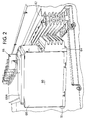
- Figure 2 is a perspective view of one embodiment of the fuse switch unit partially connected to a panelboard;
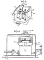
- Figure 3 illustrates one embodiment of the inside of the switch unit, and
- Figure 4 is a side cross-sectional view of Figure 3 along a line IV - IV just within the housing wall of the switch unit with a fuse connected between the fuse lugs.
- For a better understanding of the present invention together with other and further advantages, and capabilities thereof, reference is made to the following disclosure and appended claims in connection with the above-described drawings.
- In order to understand more clearly the present invention, a short discussion of the prior art, in particular Figure 1, will be provided. Figure 1 illustrates a switch fuse unit having a molded
plastic case 10 divided by apartition 12 into aswitch compartment 14 and afuse compartment 16. The unit would normally provide a switch and a fuse on each of three phases, only one phase being shown in the drawings. The input end of thecase 10 is closed by a finnedplastic block 18 forming threeterminal channels input terminal 26 shown is positioned in thechannel 22, while terminals for the other phases (not shown) would be withinchannels - The
input terminal 26 is located on one face ofcase 10 and is connected to astationary switch 28 which cooperates with a movableswitch contact blade 30 to make and break the circuit. Thereafter, the circuit passes via afuse link 32 tooutput terminal 34 located on one face of thecase 10. The other phases also have similar fuse links similar tofuse link 32. Themovable contact blade 30 is mounted, with those of the other phases, in slots in aninsulating shaft 40 rotatably mounted within thecase 10. The path of contact movement is within anarc chute 56 of a known type. Anextemal operating handle 38 secured toshaft 42 can be moved between the "off" position shown in full and the "on" position shown in broken lines. This rotates aclaw member 44 secured to theshaft 42, which in turn drives apin 46 which actuates a quick make and break mechanism, generally indicated at 48. Themechanism 48 is of the general type shown in British Patent No. 1,170,720. However, in this prior art arrangement, theclaw member 44 replaceslever 46 of the earlier patent. The switching mechanism described in U.S. Patent No. 4,496,916 and its accompanying busbar connect structure can also be used in the present invention. - Figure 1 also shows the unit with a U.S. tag-
type fuse link 32 bolted tofuse compartment lugs adapter plates 54. Fuse links having standard dimensions of British Standard No. 88 (BS88) having offset tags can also be bolted directly tolugs - Referring now to Figure 2, there is illustrated the
switch unit 60 of the present invention that is partially disconnected frombusbars 62 of a panelboard.Switch unit 60 includes plug-onconnectors 64, which are shrouded and braced in a molded protective insulator,fuse switch handle 62, which operates the switch mechanism within the switch unit,cover 68A, which forms part ofhousing 68, and finally amounting bracket 70, which forms part of the fuse switch housing which helps to support and align the load end of the fuse switch within the panelboard. - Referring to Figure 3, there is illustrated a
fuse switch 60, with the top and side covers removed, exhibiting theswitch mechanism 72. In the wall mounted position,switch unit 60 haslugs switch mechanism 72. An electrical conductor may be connected betweenlugs fuse link 32, such as shown in Figure 1, can be connected between the screws oflugs switch operating mechanism 72 is of the type shown in Figure 1 and others that are well known in the art. Thehousing 60 is of a corrosion resistant zinc coated sheet enclosure having electrostatically deposited paint finish, however it may also be made of other materials such as a molded plastic material shown in Figure 1. Its possible to operate the switch in the range with incoming ratings from 400 amps to 800 amps and outgoing fuse ratings from 6 amps to 400 amps.
Claims (3)
- A switch unit comprising:a) a housing of generally rectangular form, the housing having a number of faces;b) an inlet terminal (26) positioned on one of said faces of the housing for resilient engagement with a busbar;c) separate switch contacts electrically coupled with said inlet terminal (26)d) a switch mechanism (72) positioned within the housing, said switch mechanism (72) including an operating handle, (66), operable to open and close said contacts in a quick made and break manner;e) an outlet terminal (34) electrically coupled to said switch mechanism (72);f) link means (32) positioned within the housing and being electrically coupled in series with said inlet terminal (26), operable contacts and outlet terminal (34); characterised in that said link means (32) being mounted on the switch mechanism (72) between said mechanism (72) and the operating handle (66).
- A switch unit as claimed in claim 1 wherein said link means (32) comprises an electrical conductor.
- A switch unit as claimed in claim 1 wherein said link means comprises a fuse link (32).
Applications Claiming Priority (3)
| Application Number | Priority Date | Filing Date | Title |
|---|---|---|---|
| US723369 | 1991-06-28 | ||
| US07/723,369 US5148139A (en) | 1991-06-28 | 1991-06-28 | Fuse switch unit for panelboards |
| PCT/US1992/005100 WO1993000694A1 (en) | 1991-06-28 | 1992-06-12 | Improved fuse switch unit for panelboards |
Publications (3)
| Publication Number | Publication Date |
|---|---|
| EP0546140A1 EP0546140A1 (en) | 1993-06-16 |
| EP0546140A4 EP0546140A4 (en) | 1994-04-13 |
| EP0546140B1 true EP0546140B1 (en) | 1996-05-22 |
Family
ID=24905940
Family Applications (1)
| Application Number | Title | Priority Date | Filing Date |
|---|---|---|---|
| EP92913590A Expired - Lifetime EP0546140B1 (en) | 1991-06-28 | 1992-06-12 | Improved fuse switch unit for panelboards |
Country Status (4)
| Country | Link |
|---|---|
| US (1) | US5148139A (en) |
| EP (1) | EP0546140B1 (en) |
| DE (1) | DE69210964T2 (en) |
| WO (1) | WO1993000694A1 (en) |
Families Citing this family (14)
| Publication number | Priority date | Publication date | Assignee | Title |
|---|---|---|---|---|
| DE4326401C2 (en) * | 1993-08-06 | 2001-02-08 | Peterreins Schalttechnik Gmbh | Arrangement consisting of a switch part and a fuse part |
| EP0670581A1 (en) * | 1994-03-04 | 1995-09-06 | Weber Ag | Load break switch with fuses, in the form of a drawer unit |
| US5609245A (en) * | 1994-12-20 | 1997-03-11 | Square D Company | Modular switch interior assembly and method of assembling same |
| US5750918A (en) * | 1995-10-17 | 1998-05-12 | Foster-Miller, Inc. | Ballistically deployed restraining net |
| US5726852A (en) * | 1996-09-20 | 1998-03-10 | Reltec Corporation | Modular DC distribution unit and system |
| US6381748B1 (en) | 1997-05-02 | 2002-04-30 | Gte Main Street Incorporated | Apparatus and methods for network access using a set top box and television |
| JP2000223000A (en) * | 1999-01-27 | 2000-08-11 | Yazaki Corp | Power source breaking device |
| JP2000223001A (en) * | 1999-01-27 | 2000-08-11 | Yazaki Corp | Power supply breaking device |
| JP2000223002A (en) * | 1999-01-27 | 2000-08-11 | Yazaki Corp | Power supply breaking device |
| JP2000311576A (en) | 1999-04-27 | 2000-11-07 | Yazaki Corp | Power source breaking device |
| DE102006058328B3 (en) * | 2006-12-11 | 2008-05-08 | Siemens Ag | Multi-phase strand safety module, has safety devices with components arranged one above other in front of connections of package between plates, which are connected with connections, where components are provided with cover at front side |
| DE102007041963B3 (en) | 2007-09-03 | 2009-03-05 | Siemens Ag | Assembly of a switchgear assembly and a fuse assembly |
| DE102010027901A1 (en) * | 2010-04-19 | 2011-10-20 | Beckhoff Automation Gmbh | Supply module |
| GB2531502A (en) * | 2014-09-15 | 2016-04-27 | Schneider Electric Ltd | Current management device |
Family Cites Families (5)
| Publication number | Priority date | Publication date | Assignee | Title |
|---|---|---|---|---|
| US2574290A (en) * | 1947-01-16 | 1951-11-06 | Gen Electric | Multiple unit switch with single actuator |
| US2937254A (en) * | 1957-02-05 | 1960-05-17 | Gen Electric | Panelboard unit |
| US3179761A (en) * | 1961-09-15 | 1965-04-20 | Gen Electric | Electrical switch and fuse housing combination having a pivotally mounted adapting mechanism operable independently of its movable cover |
| GB8301042D0 (en) * | 1982-01-27 | 1983-02-16 | Square D Co | Switch-fuse unit |
| DE8716968U1 (en) * | 1987-12-24 | 1989-04-27 | Wickmann-Werke Gmbh, 5810 Witten, De |
-
1991
- 1991-06-28 US US07/723,369 patent/US5148139A/en not_active Expired - Lifetime
-
1992
- 1992-06-12 WO PCT/US1992/005100 patent/WO1993000694A1/en active IP Right Grant
- 1992-06-12 DE DE69210964T patent/DE69210964T2/en not_active Expired - Fee Related
- 1992-06-12 EP EP92913590A patent/EP0546140B1/en not_active Expired - Lifetime
Also Published As
| Publication number | Publication date |
|---|---|
| DE69210964D1 (en) | 1996-06-27 |
| DE69210964T2 (en) | 1996-10-24 |
| EP0546140A1 (en) | 1993-06-16 |
| US5148139A (en) | 1992-09-15 |
| EP0546140A4 (en) | 1994-04-13 |
| WO1993000694A1 (en) | 1993-01-07 |
Similar Documents
| Publication | Publication Date | Title |
|---|---|---|
| EP0546140B1 (en) | Improved fuse switch unit for panelboards | |
| US5304761A (en) | Arc-proof molded case circuit breaker | |
| US5510960A (en) | Connector assembly for a motor control unit | |
| US5539168A (en) | Power circuit breaker having a housing structure with accessory equipment for the power circuit breaker | |
| US5657193A (en) | Electronic control module for motor controller units | |
| CA2155405C (en) | Interlock mechanism for a motor control unit | |
| US20100133078A1 (en) | Installation switching device | |
| CA2238724C (en) | Combined wire lead and interphase barrier for power switches | |
| US4496916A (en) | Switch fuse unit | |
| US9129768B2 (en) | Multipole electrical switching device | |
| US5321378A (en) | Molded case circuit breaker current transformer adapter unit | |
| CA1265605A (en) | Metalclad substation subdivided into tight compartments | |
| US6064018A (en) | Molded case circuit breaker molded pole assembly | |
| US6175486B1 (en) | Switch gear for medium voltage with separately connectable multiple phases | |
| CN100524562C (en) | Switching protective device comprising fuses | |
| US5557498A (en) | Switching apparatus including a displaceable disconnecting device and an auxiliary circuit | |
| US2924688A (en) | End mounting of a current limiting device associated with a circuit breaker | |
| WO1996024941A1 (en) | Secondary disconnect assembly for high ampere-circuit breaker | |
| GB2036437A (en) | Improvements in and Relating to Circuit Breakers | |
| US9263860B2 (en) | Power distribution system, and switchgear assembly, and mounting member therefor | |
| EP1346387B1 (en) | Supporting base for a circuit breaker | |
| EP2020669B1 (en) | Electrical connection auxiliary module for circuit breakers. | |
| HU225923B1 (en) | Electrical connection device for two electrical apparatus such as an electrical protection device combined with a controlled switch, and electrical apparatus adapted to such device. | |
| CN111696816A (en) | Insulation switch equipment of electric power system | |
| US2949516A (en) | Reposition terminals for circuit breaker base extension |
Legal Events
| Date | Code | Title | Description |
|---|---|---|---|
| PUAI | Public reference made under article 153(3) epc to a published international application that has entered the european phase |
Free format text: ORIGINAL CODE: 0009012 |
|
| 17P | Request for examination filed |
Effective date: 19930320 |
|
| AK | Designated contracting states |
Kind code of ref document: A1 Designated state(s): DE FR GB IT |
|
| A4 | Supplementary search report drawn up and despatched |
Effective date: 19940221 |
|
| AK | Designated contracting states |
Kind code of ref document: A4 Designated state(s): DE FR GB IT |
|
| 17Q | First examination report despatched |
Effective date: 19950505 |
|
| GRAH | Despatch of communication of intention to grant a patent |
Free format text: ORIGINAL CODE: EPIDOS IGRA |
|
| GRAA | (expected) grant |
Free format text: ORIGINAL CODE: 0009210 |
|
| AK | Designated contracting states |
Kind code of ref document: B1 Designated state(s): DE FR GB IT |
|
| REF | Corresponds to: |
Ref document number: 69210964 Country of ref document: DE Date of ref document: 19960627 |
|
| ET | Fr: translation filed | ||
| ITF | It: translation for a ep patent filed |
Owner name: STUDIO TORTA SOCIETA' SEMPLICE |
|
| PG25 | Lapsed in a contracting state [announced via postgrant information from national office to epo] |
Ref country code: DE Effective date: 19970301 |
|
| PLBE | No opposition filed within time limit |
Free format text: ORIGINAL CODE: 0009261 |
|
| STAA | Information on the status of an ep patent application or granted ep patent |
Free format text: STATUS: NO OPPOSITION FILED WITHIN TIME LIMIT |
|
| 26N | No opposition filed | ||
| REG | Reference to a national code |
Ref country code: GB Ref legal event code: IF02 |
|
| PG25 | Lapsed in a contracting state [announced via postgrant information from national office to epo] |
Ref country code: IT Free format text: LAPSE BECAUSE OF NON-PAYMENT OF DUE FEES Effective date: 20050612 |
|
| REG | Reference to a national code |
Ref country code: FR Ref legal event code: ST Effective date: 20100226 |
|
| PG25 | Lapsed in a contracting state [announced via postgrant information from national office to epo] |
Ref country code: FR Free format text: LAPSE BECAUSE OF NON-PAYMENT OF DUE FEES Effective date: 20090630 |
|
| PGFP | Annual fee paid to national office [announced via postgrant information from national office to epo] |
Ref country code: FR Payment date: 20080424 Year of fee payment: 17 |
|
| PGFP | Annual fee paid to national office [announced via postgrant information from national office to epo] |
Ref country code: GB Payment date: 20110523 Year of fee payment: 20 |
|
| REG | Reference to a national code |
Ref country code: GB Ref legal event code: PE20 Expiry date: 20120611 |
|
| PG25 | Lapsed in a contracting state [announced via postgrant information from national office to epo] |
Ref country code: GB Free format text: LAPSE BECAUSE OF EXPIRATION OF PROTECTION Effective date: 20120611 |