EP0545986B1 - A method to operate with a wire-guided, in air or water, movable vehicle and a device for carrying out the method - Google Patents
A method to operate with a wire-guided, in air or water, movable vehicle and a device for carrying out the method Download PDFInfo
- Publication number
- EP0545986B1 EP0545986B1 EP91914948A EP91914948A EP0545986B1 EP 0545986 B1 EP0545986 B1 EP 0545986B1 EP 91914948 A EP91914948 A EP 91914948A EP 91914948 A EP91914948 A EP 91914948A EP 0545986 B1 EP0545986 B1 EP 0545986B1
- Authority
- EP
- European Patent Office
- Prior art keywords
- support
- vehicle
- wire
- buoyancy
- reconnaissance
- Prior art date
- Legal status (The legal status is an assumption and is not a legal conclusion. Google has not performed a legal analysis and makes no representation as to the accuracy of the status listed.)
- Expired - Lifetime
Links
Images


Classifications
-
- G—PHYSICS
- G01—MEASURING; TESTING
- G01V—GEOPHYSICS; GRAVITATIONAL MEASUREMENTS; DETECTING MASSES OR OBJECTS; TAGS
- G01V1/00—Seismology; Seismic or acoustic prospecting or detecting
- G01V1/38—Seismology; Seismic or acoustic prospecting or detecting specially adapted for water-covered areas
- G01V1/3843—Deployment of seismic devices, e.g. of streamers
-
- B—PERFORMING OPERATIONS; TRANSPORTING
- B63—SHIPS OR OTHER WATERBORNE VESSELS; RELATED EQUIPMENT
- B63C—LAUNCHING, HAULING-OUT, OR DRY-DOCKING OF VESSELS; LIFE-SAVING IN WATER; EQUIPMENT FOR DWELLING OR WORKING UNDER WATER; MEANS FOR SALVAGING OR SEARCHING FOR UNDERWATER OBJECTS
- B63C11/00—Equipment for dwelling or working underwater; Means for searching for underwater objects
- B63C11/48—Means for searching for underwater objects
-
- F—MECHANICAL ENGINEERING; LIGHTING; HEATING; WEAPONS; BLASTING
- F42—AMMUNITION; BLASTING
- F42B—EXPLOSIVE CHARGES, e.g. FOR BLASTING, FIREWORKS, AMMUNITION
- F42B22/00—Marine mines, e.g. launched by surface vessels or submarines
- F42B22/10—Moored mines
- F42B22/14—Moored mines at a variable depth setting
- F42B22/16—Moored mines at a variable depth setting using mechanical means, e.g. plummet and float
Definitions
- the present invention relates to a method to operate a control wire-guided, in air or water, movable vehicle and a device for carrying out the method.
- the invention has emerged when starting from problems concerning underwater vehicles or put in another way, torpedoes and will therefore mainly be symbolizefied with such.
- the present problem exist, however, also in an application with air vehicles and also in this case it can be solved in the same way, so the invention relates also to such vehicles.
- a possible solution to the raised problem is to use some form of a wire-guided torpedo-mine, that is a wire guided torpedo that rests on a support on the bottom until it is activated, whereupon it swims away on its commission. It is in this case possible to have an operator on the shore, connected to the support with a cable, for example an optical fibre, for communication and possibly also an usual two-wire cable for power supply.
- a cable for example an optical fibre, for communication and possibly also an usual two-wire cable for power supply.
- the embodiment that is shown in the figures relates to a reconnaissance and/or weapon system for underwater use and comprises a vehicle 1, in the following in the description of this system called torpedo, and a support 2 for it.
- the support is connected with an operator site, preferably on the shore, with a wire connection.
- This wire which is intended to lie still, preferably has a higher density than that of water, so it lies on the bottom.
- the support 2 is connected to the torpedo 1 with a wire 3, here called the control wire, which has a density somewhat lower than that of water. The wire will therefore float in the water and does therefore not strive to lie down on the bottom.
- wire magazines from which the wire is fed out, when the torpedo leaves.
- wire magazines both in the support 2 and the torpedo 1.
- a wire magazine in one end of the wire is enough.
- a reconnaissance torpedo travels about for quite a long time, during which the distance to the support is reduced from time to time, moreover it returns at intervals to a rest position on the support. In this case a wire magazine that is able to wind or reel the wire back is needed. Also in the case with a weapon torpedo this can be of interest as the target can make sharp turns etc.
- the invention overcomes by being provided with a device 4 having buoyancy, in this underwater application in the following called float, connected to the support 2 and being arranged to be able to raise the control wire 3 from the bottom 5 to a position close to the surface 6.
- the float 4 consists of a floating body that is attached to one or more lines 7, which are possible to wind on a winding apparatus 8.
- the winding apparatus can be controlled to unwind and then wind a suitable part of the line or lines 7.
- the control wire 3 runs from the support 2, through a hole in the float 4 and further to the torpedo 1.
- line or lines 7 are provided with transversal struts 9. They thereby create a device looking like a rope-ladder.
- the distance between the struts 9 is suitably shorter than the length of the adjacent struts 9, which will prevent them from getting entangled by one strut being stuck into an adjacent gap.
- the "rope-ladder” is suitably designed with gradually shorter struts counted from the support 2 towards the float 4 and thereby it also has a decreasing distance between the struts.
- the "rope-ladder” hereby becomes more difficult to detect with a hydroacoustical sensor, as the interference between reflexes from the struts is avoided.
- the struts 9 can be made of tubes of fibreglass reinforced plastic. Through the tubes, between the longitudinal lines 7, a nylon line is drawn, which is of the same kind as the one the longitudinal lines are made from.
- the outer diameter of the struts could for instance be 7 mm and their inner diameter 5 mm.
- the float 4 is a toroid, and the control wire 3 runs through the central hole of the toroid.
- the toroid consists of a hard and smooth shell, made for instance of plastic, which on the inside is filled up with a pressure resistant floating material, for instance bonocell.
- accumulators in the support 2. These can either be charged via the wire from the operator site or from thermic batteries in the support, which are activated as the need for charging current arises. Also in the torpedo 1 there are accumulatos, that are charged from the support 2, when the torpedo is in its rest position.
- the float 4 can either at first be released an adapted length by means of the winding apparatus 8 and then the torpedo 1 be released from a locking device, for example in the form of a motor-driven or magneticly driven male contact on the torpedo, which is in contact with a female contact on the support, the contacts are also at the same time used to feed charging current. Then the torpedo is givenbuoyancy, for instance by emplying a water-bag in the torpedo or by activating water-jets in the torpedo directed downwards. Thereafter the propulsion engines are started. Alternatively the torpedo 1 can be released before the float 4 or on the whole at the same time.
- a locking device for example in the form of a motor-driven or magneticly driven male contact on the torpedo, which is in contact with a female contact on the support, the contacts are also at the same time used to feed charging current. Then the torpedo is givenbuoyancy, for instance by emplying a water-bag
- the corresponding technique can, after a certain adjustment, be used also for atmosphere vehicles, such as wire guided helicopters or propelled airships.
- control wire 3 in the underwater case is an optical fibre, it must have a special water-resistant sheath, which will make it thicker. It is, however, easy to give it a density that is somewhat lower than that of water.
- the wire 3 can for obvious reasons not be lighter than air, but an optical fibre does not in this case need an advanced sheath and can be made very thin and light, so that the wire tension between the vehicle and the lifting device 4 can keep it up.
Abstract
Description
- The present invention relates to a method to operate a control wire-guided, in air or water, movable vehicle and a device for carrying out the method. The invention has emerged when starting from problems concerning underwater vehicles or put in another way, torpedoes and will therefore mainly be exemplefied with such. The present problem exist, however, also in an application with air vehicles and also in this case it can be solved in the same way, so the invention relates also to such vehicles.
- In order to stop foreign underwater vehicles from operating in the Swedish archipelago, it is necessary to be able to continuously guard important entrances to inner water and provide a serious threat to damage an intruding submarine, if it tries to penetrate. It is also necessary to effectively close the inner water, if a submarine has penetrated and establish a serious threat to this submarine if it tries to break out. A system that shall cope with this task should among other things be transportable and possess a great endurance and have a high probability of hit and effect. Due to a difficult bottom topography and a difficult hydroacoustical environment in our inner archipelagoes, it is necessary, when using an active hydroacoustical homing device, that target data are transmitted to an operator, who makes the classification of hydrophone echoes.
- A possible solution to the raised problem is to use some form of a wire-guided torpedo-mine, that is a wire guided torpedo that rests on a support on the bottom until it is activated, whereupon it swims away on its commission. It is in this case possible to have an operator on the shore, connected to the support with a cable, for example an optical fibre, for communication and possibly also an usual two-wire cable for power supply.
- Between the support and the torpedo, or more generally put, the vehicle, in a corresponding way, a wire is running for the transmission of information, that is guidance information for the torpedo and, in the reconnaissance case, reconnaissance results from the torpedo. This far the present systems are previously known, at least as ideas, but here a serious problem arises in Swedish waters. The bottoms are here, along great parts of the coast, rocky and stony and therefore there is a great risk that the wire between the vehicle and the support gets caught somewhere and gets broken. This serious problem is solved by the invention by giving it the design that is evident from the independent claims.
- Corresponding problems exist for wire guided air or atmosphere vehicles, for instance remotely controlled reconnaissance helicopters or remotely controlled propelled airships. The wire can easily get caught in trees or the like in the vicinity of the vehicle support. Also this problem is solved by the invention in a corresponding way.
- In the following the invention will be described in more detail under reference to the attached drawings where,
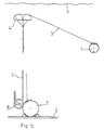
- fig 1 a-c show an embodiment of the invention in an underwater application from the front,
- fig 2 a-c show the corresponding embodiment from the side and
- fig 3 shows a cross section through an embodiment of a device having buoyancy and being part of the invention.
- The embodiment that is shown in the figures relates to a reconnaissance and/or weapon system for underwater use and comprises a
vehicle 1, in the following in the description of this system called torpedo, and asupport 2 for it. The support is connected with an operator site, preferably on the shore, with a wire connection. This wire, which is intended to lie still, preferably has a higher density than that of water, so it lies on the bottom. Further, thesupport 2 is connected to thetorpedo 1 with awire 3, here called the control wire, which has a density somewhat lower than that of water. The wire will therefore float in the water and does therefore not strive to lie down on the bottom. - In the
support 2 and/or thetorpedo 1 there are wire magazines from which the wire is fed out, when the torpedo leaves. In order for the wire feeding to work at quick accelerations etc., it is adviceble to have wire magazines both in thesupport 2 and thetorpedo 1. In certain applications it is nevertheless possible, that a wire magazine in one end of the wire is enough. A reconnaissance torpedo travels about for quite a long time, during which the distance to the support is reduced from time to time, moreover it returns at intervals to a rest position on the support. In this case a wire magazine that is able to wind or reel the wire back is needed. Also in the case with a weapon torpedo this can be of interest as the target can make sharp turns etc. - When a lot of wire is fed out, there is a risk that it will get caught by bottom formations at some point, even if it has some buoyancy. It is this the invention overcomes by being provided with a
device 4 having buoyancy, in this underwater application in the following called float, connected to thesupport 2 and being arranged to be able to raise thecontrol wire 3 from thebottom 5 to a position close to thesurface 6. - The
float 4 consists of a floating body that is attached to one ormore lines 7, which are possible to wind on awinding apparatus 8. The winding apparatus can be controlled to unwind and then wind a suitable part of the line orlines 7. Thecontrol wire 3 runs from thesupport 2, through a hole in thefloat 4 and further to thetorpedo 1. - An advantageous design of said line or
lines 7 is to make them as two lines, which along their lengths are provided withtransversal struts 9. They thereby create a device looking like a rope-ladder. The distance between thestruts 9 is suitably shorter than the length of theadjacent struts 9, which will prevent them from getting entangled by one strut being stuck into an adjacent gap. - The "rope-ladder" is suitably designed with gradually shorter struts counted from the
support 2 towards thefloat 4 and thereby it also has a decreasing distance between the struts. The "rope-ladder" hereby becomes more difficult to detect with a hydroacoustical sensor, as the interference between reflexes from the struts is avoided. - In an advantageous design the
struts 9 can be made of tubes of fibreglass reinforced plastic. Through the tubes, between thelongitudinal lines 7, a nylon line is drawn, which is of the same kind as the one the longitudinal lines are made from. The outer diameter of the struts could for instance be 7 mm and theirinner diameter 5 mm. - Below a theoretic calculation of the design of the "rope-ladder" is given. Within brackets concrete figures for an example is provided.

- Then the following is valid:
1N = aN1o
which gives
where
- This gives

- In an advantageous design of the invention, the
float 4 is a toroid, and thecontrol wire 3 runs through the central hole of the toroid. The toroid consists of a hard and smooth shell, made for instance of plastic, which on the inside is filled up with a pressure resistant floating material, for instance bonocell. - For the power supply there are suitably accumulators in the
support 2. These can either be charged via the wire from the operator site or from thermic batteries in the support, which are activated as the need for charging current arises. Also in thetorpedo 1 there are accumulatos, that are charged from thesupport 2, when the torpedo is in its rest position. - To activate the torpedo, the
float 4 can either at first be released an adapted length by means of thewinding apparatus 8 and then thetorpedo 1 be released from a locking device, for example in the form of a motor-driven or magneticly driven male contact on the torpedo, which is in contact with a female contact on the support, the contacts are also at the same time used to feed charging current. Then the torpedo is givenbuoyancy, for instance by emplying a water-bag in the torpedo or by activating water-jets in the torpedo directed downwards. Thereafter the propulsion engines are started. Alternatively thetorpedo 1 can be released before thefloat 4 or on the whole at the same time. - If it is a reconnaissance torpedo, which is to be re-used, it must be able to return to its rest position on the support in order i.a. to recharge the accumulators. The torpedo is then guided to a position above the support, after which the
float 4 is pulled down by thewinding apparatus 8 and the torpedo is made to descend to its rest position. Among other things due to the design of the support, it is possible also in this case to imagine this to happen in optional order or simultaneously. It could be advicable to provide thesupport 2 with a TV-camera directed upwards in order to monitor the final docking. - As was previously stated, the corresponding technique can, after a certain adjustment, be used also for atmosphere vehicles, such as wire guided helicopters or propelled airships.
- Unlike the conditions for underwater vehicles, it is easy to control atmosphere vehicles via radio communication. There are, however, several disadvantages. The control signal can be intercepted by others and also jammed. In the reconnaissance application the most important thing is, however, that transmission of large amounts of information, such as for instance images, in real time requests a very large bandwidth, which in its turn requests a radio-link connection of an extreme character (and cost) and gives problems i.a. with the directing of the antennas. If on the other hand an optical fibre could be used for the transmission, an excellent, jam resistant, wide band connection is achieved. Then, however, a problem is, as mentioned previously, that the fibre can get caught in trees etc., which however, can be remedied by the invention by lifting the
control wire 3 by adevice 4 having buoyancy, such as a gas balloon. The geometrical design of thelifting device 4 as well as itsline arrangement 7 are of the same kind as the one that was previously described in the underwater case. - If the
control wire 3 in the underwater case is an optical fibre, it must have a special water-resistant sheath, which will make it thicker. It is, however, easy to give it a density that is somewhat lower than that of water. In the air case thewire 3 can for obvious reasons not be lighter than air, but an optical fibre does not in this case need an advanced sheath and can be made very thin and light, so that the wire tension between the vehicle and thelifting device 4 can keep it up. - Especially in the helicopter case, where the vehicle is heavier than air, one wants to minimize the weight of the vehicle, so in this case one usually also minimize the carried wire magazine. It is probably difficult to be completely without a wire magazine in the helicopters, as otherwise sudden pulls in the wire can tear it in two.
Claims (10)
- A method to operate a control wire guided, in air or water movable vehicle (1) from a support (2), characterized in that the vehicle and/or the support is provided with a wire magazine for the control wire (3), that the support is provided with a winding apparatus (8) and with a device (4) having buoyancy, which is fastened to one or more lines (7), arranged to be wound or unwound by said winding apparatus (8), and having a rest position on or adjacent the support, that the control wire (3) of the vehicle is drawn from the support through a hole in the device (4) having buoyancy, that at the launch of the vehicle (1) the winding apparatus (8) is made to un-wind a predetermined length of the line or lines (7), at which the device (4) having buoyancy will rise to the degree the line or lines admit, while the control wire (3) is drawn out of the wire magazine or magazines, and that the vehicle (1) before, after or at the same time as the device (4) having buoyancy is made to leave the support (2) and then during the move will receive guidance information from the support and possibly send back information from a sensor that is installed in the vehicle.
- A method according to claim 1, characterized in that the vehicle (1) at the return to its rest position, at first is guided to a position above the support (2), after which, in optional order or simultaneously, the device (4) having buoyancy is pulled down by the winding apparatus (8) to its rest position and the vehicle is made to descend to its rest position.
- Reconnaissance and/or weapon system comprising a control wire guided, in air or water movable vehicle (1) and a support (2) for it, characterized in that the vehicle and/or the support has a wire magazine for the control wire (3), that the support is provided with a winding apparatus (8) and with a device (4) having buyoancy, which is fastened to one or more lines (7), arranged to be wound or un-wound by said winding apparatus (8) and having a rest position on or adjacent the support (2), that the control wire (3) of the vehicle is drawn from the support through a hole in the device (4) having buoyancy to the vehicle.
- Reconnaissance and/or weapon system according to claim 3, characterized in that said line or lines (7) are two lines, which are provided with transversal struts (9) along their lengths, in order to create a rope-ladder shaped device, at which the distance between the struts is shorter than the length of the adjacent struts.
- Reconnaissance and/or weapon system according to claim 4, characterized in that the length of the struts (9) decreases from the support towards the device (4) having buoyancy.
- Reconnaissance and/or weapon system according to claim 4 or 5, characterized in that the struts (9) are made of tubes through which a transversal line between the longitudinal lines (7) runs, which transversal line is of the same material as said longitudinal lines.
- Reconnaissance and/or weapon system according to one of the claims 3-6, characterized in that the device (4) having buoyancy is a toroid and the control wire runs through its central hole.
- Reconnaissance and/or weapon system according to one of the claims 3-7, characterized in that it is an underwater system, in which the vehicle (1) is a reconnaissance or weapon torpedo and the control wire (3) has a density that is somewhat lower than that of water.
- Reconnaissance and/or weapon system according to one of the claims 3-7, characterized in that it is an atmosphere system, in which the vehicle (1) is an airship having a propulsion system.
- Reconnaissance and/or weapon system according to one of the claims 3-7, characterized in that it is an atmosphere system, in which the vehicle (1) is a remotely controlled helicopter.
Applications Claiming Priority (3)
| Application Number | Priority Date | Filing Date | Title |
|---|---|---|---|
| SE9002760 | 1990-08-29 | ||
| SE9002760A SE466927B (en) | 1990-08-29 | 1990-08-29 | SETTING TO OPERATE WITH A WIRELESS, AIR OR WATER MOVABLE VEHICLE AND A DEVICE TO IMPLEMENT THE SET |
| PCT/SE1991/000560 WO1992004590A1 (en) | 1990-08-29 | 1991-08-23 | A method to operate with a wire-guided, in air or water, movable vehicle and a device for carrying out the method |
Publications (2)
| Publication Number | Publication Date |
|---|---|
| EP0545986A1 EP0545986A1 (en) | 1993-06-16 |
| EP0545986B1 true EP0545986B1 (en) | 1995-07-05 |
Family
ID=20380231
Family Applications (1)
| Application Number | Title | Priority Date | Filing Date |
|---|---|---|---|
| EP91914948A Expired - Lifetime EP0545986B1 (en) | 1990-08-29 | 1991-08-23 | A method to operate with a wire-guided, in air or water, movable vehicle and a device for carrying out the method |
Country Status (8)
| Country | Link |
|---|---|
| US (1) | US5377164A (en) |
| EP (1) | EP0545986B1 (en) |
| CA (1) | CA2088362A1 (en) |
| DE (1) | DE69111071D1 (en) |
| FI (1) | FI930895A0 (en) |
| NO (1) | NO302439B1 (en) |
| SE (1) | SE466927B (en) |
| WO (1) | WO1992004590A1 (en) |
Cited By (1)
| Publication number | Priority date | Publication date | Assignee | Title |
|---|---|---|---|---|
| CN104076399A (en) * | 2014-06-06 | 2014-10-01 | 中国石油集团东方地球物理勘探有限责任公司 | Earthquake collecting construction method for submarine cables in scallop breeding area |
Families Citing this family (6)
| Publication number | Priority date | Publication date | Assignee | Title |
|---|---|---|---|---|
| FR2722164B1 (en) * | 1994-07-08 | 1996-09-13 | Eca | IMPROVED PROCESS FOR THE DESTRUCTION OF AN UNDERWATER OBJECT, ESPECIALLY FROM A SUBMERSIBLE MINE |
| US5503059A (en) * | 1995-01-03 | 1996-04-02 | Pacholok; David R. | Vehicle disabling device and method |
| US5637826A (en) * | 1996-02-07 | 1997-06-10 | The United States Of America As Represented By The Secretary Of The Navy | Method and apparatus for optimal guidance |
| US6738314B1 (en) | 2003-01-31 | 2004-05-18 | L3 Communications Corporation | Autonomous mine neutralization system |
| US6712312B1 (en) * | 2003-01-31 | 2004-03-30 | The United States Of America As Represented By The Secretary Of The Navy | Reconnaissance using unmanned surface vehicles and unmanned micro-aerial vehicles |
| AU2008211586A1 (en) * | 2007-01-31 | 2008-08-07 | Armscor Business (Pty) Ltd | Underwater buoy system |
Family Cites Families (5)
| Publication number | Priority date | Publication date | Assignee | Title |
|---|---|---|---|---|
| US2422337A (en) * | 1940-04-19 | 1947-06-17 | Chilowsky Constantin | Submarine detecting buoy |
| US3161168A (en) * | 1961-09-28 | 1964-12-15 | Loral Electronics Corp | Submarine self-propelling device |
| US4004265A (en) * | 1974-08-02 | 1977-01-18 | Sanders Associates, Inc. | Self-propelled array system |
| US4557697A (en) * | 1982-07-22 | 1985-12-10 | Institut Okeanologii Imeni P.P. Shirshova | Method of delivering to ocean bottom and raising to surface of station for deep water researches and design of station delivered using said method |
| US4794575A (en) * | 1987-10-02 | 1988-12-27 | The United States Of America As Represented By The Secretary Of The Navy | Submarine launched sea-state buoy (SLSSB) |
-
1990
- 1990-08-29 SE SE9002760A patent/SE466927B/en not_active IP Right Cessation
-
1991
- 1991-08-23 CA CA002088362A patent/CA2088362A1/en not_active Abandoned
- 1991-08-23 DE DE69111071T patent/DE69111071D1/en not_active Expired - Lifetime
- 1991-08-23 US US08/039,323 patent/US5377164A/en not_active Expired - Fee Related
- 1991-08-23 WO PCT/SE1991/000560 patent/WO1992004590A1/en active IP Right Grant
- 1991-08-23 EP EP91914948A patent/EP0545986B1/en not_active Expired - Lifetime
-
1993
- 1993-02-26 NO NO930730A patent/NO302439B1/en unknown
- 1993-02-26 FI FI930895A patent/FI930895A0/en unknown
Cited By (2)
| Publication number | Priority date | Publication date | Assignee | Title |
|---|---|---|---|---|
| CN104076399A (en) * | 2014-06-06 | 2014-10-01 | 中国石油集团东方地球物理勘探有限责任公司 | Earthquake collecting construction method for submarine cables in scallop breeding area |
| CN104076399B (en) * | 2014-06-06 | 2017-03-01 | 中国石油集团东方地球物理勘探有限责任公司 | A kind of scallop culture area submarine cable earthquake-capturing construction method |
Also Published As
| Publication number | Publication date |
|---|---|
| NO302439B1 (en) | 1998-03-02 |
| FI930895A (en) | 1993-02-26 |
| CA2088362A1 (en) | 1992-03-01 |
| FI930895A0 (en) | 1993-02-26 |
| DE69111071D1 (en) | 1995-08-10 |
| US5377164A (en) | 1994-12-27 |
| SE9002760D0 (en) | 1990-08-29 |
| WO1992004590A1 (en) | 1992-03-19 |
| EP0545986A1 (en) | 1993-06-16 |
| SE466927B (en) | 1992-04-27 |
| NO930730D0 (en) | 1993-02-26 |
| NO930730L (en) | 1993-04-29 |
| SE9002760L (en) | 1992-03-01 |
Similar Documents
| Publication | Publication Date | Title |
|---|---|---|
| US6854410B1 (en) | Underwater investigation system using multiple unmanned vehicles | |
| US6600695B1 (en) | Method and apparatus for retrieving an unmanned underwater vehicle | |
| US8831393B2 (en) | Unmanned underwater vehicle and device for connection of an optical waveguide cable to an unmanned underwater vehicle | |
| US4004265A (en) | Self-propelled array system | |
| US20200010193A1 (en) | Method and Apparatus for Unmanned Aerial Maritime Float Vehicle That Sense and Report Relevant Data from Physical and Operational Environment | |
| US4272835A (en) | Master buoy system for acoustic array deployment, using underwater glide bodies remotely launched from a submerged pod | |
| US8817574B2 (en) | Method and system of a compound buoy | |
| NO20151033L (en) | Active management of marine seismic sources | |
| EP3835834A1 (en) | Sensor node | |
| WO2009023058A2 (en) | Hybrid remotely/autonomously operated underwater vehicle | |
| JP6595900B2 (en) | Autonomous unmanned submersible | |
| JP2813558B2 (en) | Underwater object destruction method | |
| EP0545986B1 (en) | A method to operate with a wire-guided, in air or water, movable vehicle and a device for carrying out the method | |
| US20130225069A1 (en) | Anchor Data Communication System | |
| US6536743B2 (en) | Fixed umbilical cable flotation docking head | |
| US6883452B1 (en) | Plunging towed array antenna | |
| US5248978A (en) | Underwater guide vehicle for removal of submerged and floating navigational hazards | |
| Ferguson | The Theseus autonomous underwater vehicle. Two successful missions | |
| US4494938A (en) | Master buoy system for acoustic array deployment, using underwater glide bodies remotely launched from a submerged pod | |
| US4019453A (en) | Underwater vehicle | |
| US5419512A (en) | Towed fiber optic data link payout system | |
| EP0089344B1 (en) | Float arrangement | |
| US6612244B1 (en) | Method and device for destroying drifting sea mines | |
| DE102017128319A1 (en) | Buoy to assist navigation and / or communication of a submarine | |
| Aoki et al. | Development of deep sea free swimming ROV" UROV7K" |
Legal Events
| Date | Code | Title | Description |
|---|---|---|---|
| PUAI | Public reference made under article 153(3) epc to a published international application that has entered the european phase |
Free format text: ORIGINAL CODE: 0009012 |
|
| 17P | Request for examination filed |
Effective date: 19930325 |
|
| AK | Designated contracting states |
Kind code of ref document: A1 Designated state(s): CH DE DK ES FR GB GR IT LI |
|
| 17Q | First examination report despatched |
Effective date: 19941212 |
|
| RAP1 | Party data changed (applicant data changed or rights of an application transferred) |
Owner name: FOERSVARETS FORSKNINGSANSTALT |
|
| GRAA | (expected) grant |
Free format text: ORIGINAL CODE: 0009210 |
|
| AK | Designated contracting states |
Kind code of ref document: B1 Designated state(s): CH DE DK ES FR GB GR IT LI |
|
| PG25 | Lapsed in a contracting state [announced via postgrant information from national office to epo] |
Ref country code: ES Free format text: THE PATENT HAS BEEN ANNULLED BY A DECISION OF A NATIONAL AUTHORITY Effective date: 19950705 Ref country code: FR Effective date: 19950705 Ref country code: LI Effective date: 19950705 Ref country code: DK Effective date: 19950705 Ref country code: GR Free format text: LAPSE BECAUSE OF FAILURE TO SUBMIT A TRANSLATION OF THE DESCRIPTION OR TO PAY THE FEE WITHIN THE PRESCRIBED TIME-LIMIT Effective date: 19950705 Ref country code: CH Effective date: 19950705 Ref country code: IT Free format text: LAPSE BECAUSE OF FAILURE TO SUBMIT A TRANSLATION OF THE DESCRIPTION OR TO PAY THE FEE WITHIN THE PRE;WARNING: LAPSES OF ITALIAN PATENTS WITH EFFECTIVE DATE BEFORE 2007 MAY HAVE OCCURRED AT ANY TIME BEFORE 2007. THE CORRECT EFFECTIVE DATE MAY BE DIFFERENT FROM THE ONE RECORDED.SCRIBED TIME-LIMIT Effective date: 19950705 |
|
| REF | Corresponds to: |
Ref document number: 69111071 Country of ref document: DE Date of ref document: 19950810 |
|
| PG25 | Lapsed in a contracting state [announced via postgrant information from national office to epo] |
Ref country code: GB Effective date: 19951005 |
|
| PG25 | Lapsed in a contracting state [announced via postgrant information from national office to epo] |
Ref country code: DE Effective date: 19951006 |
|
| REG | Reference to a national code |
Ref country code: CH Ref legal event code: PL |
|
| EN | Fr: translation not filed | ||
| PLBE | No opposition filed within time limit |
Free format text: ORIGINAL CODE: 0009261 |
|
| STAA | Information on the status of an ep patent application or granted ep patent |
Free format text: STATUS: NO OPPOSITION FILED WITHIN TIME LIMIT |
|
| GBPC | Gb: european patent ceased through non-payment of renewal fee |
Effective date: 19951005 |
|
| 26N | No opposition filed |