EP0545529B1 - Electrical connector - Google Patents
Electrical connector Download PDFInfo
- Publication number
- EP0545529B1 EP0545529B1 EP92309195A EP92309195A EP0545529B1 EP 0545529 B1 EP0545529 B1 EP 0545529B1 EP 92309195 A EP92309195 A EP 92309195A EP 92309195 A EP92309195 A EP 92309195A EP 0545529 B1 EP0545529 B1 EP 0545529B1
- Authority
- EP
- European Patent Office
- Prior art keywords
- contact
- housing
- lances
- male
- tubular portion
- Prior art date
- Legal status (The legal status is an assumption and is not a legal conclusion. Google has not performed a legal analysis and makes no representation as to the accuracy of the status listed.)
- Expired - Lifetime
Links
Images


Classifications
-
- H—ELECTRICITY
- H01—ELECTRIC ELEMENTS
- H01R—ELECTRICALLY-CONDUCTIVE CONNECTIONS; STRUCTURAL ASSOCIATIONS OF A PLURALITY OF MUTUALLY-INSULATED ELECTRICAL CONNECTING ELEMENTS; COUPLING DEVICES; CURRENT COLLECTORS
- H01R13/00—Details of coupling devices of the kinds covered by groups H01R12/70 or H01R24/00 - H01R33/00
- H01R13/40—Securing contact members in or to a base or case; Insulating of contact members
- H01R13/42—Securing in a demountable manner
- H01R13/428—Securing in a demountable manner by resilient locking means on the contact members; by locking means on resilient contact members
Definitions
- This invention relates to an electric connector for the connection of an electric circuit, and more particularly to improvements in or relating to the structure of a housing of an electric connector.
- FIG. 1 Various electric connectors are already known, and a partial view of an example of a conventional electric connector is shown in FIG. 1.
- the electric connector of the type shown is formed from a combination of an outer housing 1 having a male contact 4 and an inner housing 6 having a female contact 5.
- the inner housing 6 is fitted into the outer housing 1, whereby the male contact 4 in the outer housing 1 is force-fitted into the female contact 5 in the inner housing 6 to establish electric connection.
- Each contact 4, 5 of the male and female portions has a plurality of resilient lances 2, 7 extending laterally from the contacts, and after insertion of the male portion into the corresponding housing 1, 6, lances 2, 7 are expanded laterally in the internal spacing of each housing so as to prevent separation of the contacts 4, 5 from the housings 1, 6.
- Dimension a in FIG. 1 is defined as a dimension necessary to maintain good contact between the male and female contacts 4 and 5 after the inner housing 6 is inserted into the outer housing 1, causing the male contact 4 to fit into the female contact 5.
- Female contact may also be fixed within the inner housing by such means as soldering or by adhesive means rather than by lances.
- US-3957337 and DE-2320079 disclose oblique leaf springs or spring tongues, which project towards or into annular corners, but their inclinations are not considered. In fact the latter features axial grooves and freedoms of rotational movement.
- an electric connector comprises expansion limiting means provided on the supporting means for the lances around a portion of eacg housing in which the lances of each contact extend for the purpose of limiting excessive expansion of the lances.
- the expansion limiting means is a tubular portion making up part of the housing, the inner diameter of the tubular portion being equal to the sum of the outer diameter of each contact and a dimension of 1.4 times the length of the lances, and the outer diameter being sufficient for the expansion limiting means to reach the wall of the inner spacing of the housing.
- the tubular portion may be formed integrally with the housing or may be manufactured as a tubular member separate from the housing and securely mounted, when the housing is assembled, into the portion of the housing through which the lances of the contact extend.
- lateral expansion of the lances of the contact is limited to the inner diameter of the tubular portion, and also to an angular range of almost 45° with respect to the axial direction, and accordingly, the axial dimension necessary for the contact between the male and female contacts is assured and the reliability of the electric connection between the contacts is enhanced.
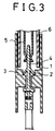
- FIG. 3 shows a partial view of the outer housing of a preferred embodiment of the present invention.
- the electric connector includes an outer housing 1 having a male contact 4 and an inner housing 6 having a female contact 5.
- the male contact 4 is inserted in the outer housing 1 and has a plurality of lances 2 extending laterally and expansible to a fixed angle due to the resiliency of the lances.
- the electric connector of the present invention is characterized in that a tubular portion 3 serving as expansion limiting means for limiting the expansion angle ⁇ of the lance 2 to within a predetermined angular range is additionally provided in the outer housing 1 as shown in FIG. 3.
- the tubular portion 3 is formed by integral molding with the outer housing 1 in such a manner as to project radially inwardly from the surface of the inner spacing of the outer housing 1.
- the tubular portion 3 may be formed from the same material as the outer housing 1 and adhered to the outer housing 1 before the male contact 4 is inserted into the outer housing 1. This makes it possible to apply the present invention to conventional electric connectors already manufactured.
- the inner diameter Di of the tubular portion 3 is equal to the dimension of the sum of the outer diameter Dc of the male contact 4 and a distance substantially equal to 1.4L.
- the length of 1.4L mentioned above signifies the length of 0.7L for each lance 2 and also signifies that the value of ⁇ defines an angle less than 45°, and accordingly, the force acting upon each lance 2 upon the axial movement of the male contact 4 has a component of force acting in the expanding direction, that is, in a radial direction from the axis of the male contact 4 which is smaller than the other component of force acting in the axial direction.
Landscapes
- Connector Housings Or Holding Contact Members (AREA)
Description
- This invention relates to an electric connector for the connection of an electric circuit, and more particularly to improvements in or relating to the structure of a housing of an electric connector.
- Various electric connectors are already known, and a partial view of an example of a conventional electric connector is shown in FIG. 1. Referring to FIG. 1, the electric connector of the type shown is formed from a combination of an
outer housing 1 having amale contact 4 and aninner housing 6 having afemale contact 5. Theinner housing 6 is fitted into theouter housing 1, whereby themale contact 4 in theouter housing 1 is force-fitted into thefemale contact 5 in theinner housing 6 to establish electric connection. Eachcontact resilient lances corresponding housing lances contacts housings - Dimension a in FIG. 1 is defined as a dimension necessary to maintain good contact between the male and
female contacts inner housing 6 is inserted into theouter housing 1, causing themale contact 4 to fit into thefemale contact 5. - Female contact may also be fixed within the inner housing by such means as soldering or by adhesive means rather than by lances.
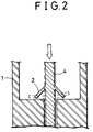
- However, when two
housings contacts contacts lances lances 2 are deformed in this manner, dimension a indicated in FIG. 1 is altered, and consequently, even if the twohousings contacts - US-3957337 and DE-2320079 disclose oblique leaf springs or spring tongues, which project towards or into annular corners, but their inclinations are not considered. In fact the latter features axial grooves and freedoms of rotational movement.
- It is an object of the present invention to provide an electric connector which assures electric connection and eliminates the problem described above.
- In order to attain the object, according to the present invention, an electric connector comprises expansion limiting means provided on the supporting means for the lances around a portion of eacg housing in which the lances of each contact extend for the purpose of limiting excessive expansion of the lances. The expansion limiting means is a tubular portion making up part of the housing, the inner diameter of the tubular portion being equal to the sum of the outer diameter of each contact and a dimension of 1.4 times the length of the lances, and the outer diameter being sufficient for the expansion limiting means to reach the wall of the inner spacing of the housing.
- The tubular portion may be formed integrally with the housing or may be manufactured as a tubular member separate from the housing and securely mounted, when the housing is assembled, into the portion of the housing through which the lances of the contact extend.
- By the means described above, lateral expansion of the lances of the contact is limited to the inner diameter of the tubular portion, and also to an angular range of almost 45° with respect to the axial direction, and accordingly, the axial dimension necessary for the contact between the male and female contacts is assured and the reliability of the electric connection between the contacts is enhanced.
- The above and other objects, features and advantages of the present invention will become apparent from the following description referring to the accompanying drawings which illustrate an example of a preferred embodiment of the present invention.
-
- FIG. 1 is a sectional view of a conventional electric connector,
- FIG. 2 is an enlarged sectional view illustrating setting or permanent set in fatigue of lances of a male connector of the conventional electric connector of FIG. 1,
- FIG. 3 is a sectional view of an electric connector showing a preferred embodiment of the present invention,
- FIG. 4 is a partial enlarged sectional view of the electric connector of FIG. 3, and
- FIG. 5 is a partial enlarged sectional view of another embodiment of the present invention.
- FIG. 3 shows a partial view of the outer housing of a preferred embodiment of the present invention. As in a conventional electric connector, the electric connector includes an
outer housing 1 having amale contact 4 and aninner housing 6 having afemale contact 5. Themale contact 4 is inserted in theouter housing 1 and has a plurality oflances 2 extending laterally and expansible to a fixed angle due to the resiliency of the lances. The electric connector of the present invention is characterized in that atubular portion 3 serving as expansion limiting means for limiting the expansion angle θ of thelance 2 to within a predetermined angular range is additionally provided in theouter housing 1 as shown in FIG. 3. Thetubular portion 3 in FIG. 3 is formed by integral molding with theouter housing 1 in such a manner as to project radially inwardly from the surface of the inner spacing of theouter housing 1. Alternatively, as shown in Fig. 5, thetubular portion 3 may be formed from the same material as theouter housing 1 and adhered to theouter housing 1 before themale contact 4 is inserted into theouter housing 1. This makes it possible to apply the present invention to conventional electric connectors already manufactured. - Referring to FIG. 4, the inner diameter Di of the
tubular portion 3 is equal to the dimension of the sum of the outer diameter Dc of themale contact 4 and a distance substantially equal to 1.4L. With this construction, even if thelances 2 lose their resiliency and are forced to expand beyond the predetermined angle, the ends of the lances will be stopped by the inner wall and the bottom surface of thetubular portion 3 so that thelances 2 will be prevented from expanding to an angle perpendicular to the axis of themale contact 4. The length of 1.4L mentioned above signifies the length of 0.7L for eachlance 2 and also signifies that the value of θ defines an angle less than 45°, and accordingly, the force acting upon eachlance 2 upon the axial movement of themale contact 4 has a component of force acting in the expanding direction, that is, in a radial direction from the axis of themale contact 4 which is smaller than the other component of force acting in the axial direction. - Above description is made concerning the male contact only but is of course applicable to the female contact having lances.
- It is to be understood that variations and modifications of the electric connector disclosed herein will be evident to those skilled in the art. It is intended that all such modifications and variations be included within the scope of the appended claims.
Claims (2)
- An electrical connector including an outer housing (1) having a male contact (4) being fixed in it, and an inner housing (6) removably coupled to the outer housing and having a female contact (5) which is contacted with the male contact when the male contact (4) is inserted into the female contact (5) for the purpose of establishing an electrical connection, wherein:at least one contact of the male and female contacts (4, 5) has, as a means of fixing the contact to a coresponding housing (1, 7), a plurality of lances (2) provided thereon that expand laterally due to the resiliency thereof, each housing (1, 6) coresponding to the contact (4, 5) having the lances 2 has a supporting means for the lances 2 and an expansion limiting means provided on the supporting means for limiting the expansion of the lances, andthe expansion limiting means includes a tubular portion (3) provided at the bottom of the housing through which the contact extends; characterized in that the tubular portion (3) has an inner diameter (Di) equal to the sum of the diameter (Dc) of the contact (4, 5) and a dimension of about 1.4 times the length (L) of the lances (2), and an outer diameter (Do) sufficient for the expansion limiting means (3) to reach the wall of the inner spacing of the housing (1, 6).
- An electrical connector as claimed in claim 1, wherein the tubular portion is a tubular member (3) formed separately from the housing (1, 6) and is securely mounted in the housing upon insertion of the contact (4, 5) into the housing.
Applications Claiming Priority (2)
| Application Number | Priority Date | Filing Date | Title |
|---|---|---|---|
| JP106742U JPH0548236U (en) | 1991-11-30 | 1991-11-30 | connector |
| JP106742/91 | 1991-11-30 |
Publications (3)
| Publication Number | Publication Date |
|---|---|
| EP0545529A2 EP0545529A2 (en) | 1993-06-09 |
| EP0545529A3 EP0545529A3 (en) | 1993-08-18 |
| EP0545529B1 true EP0545529B1 (en) | 1997-01-08 |
Family
ID=14441379
Family Applications (1)
| Application Number | Title | Priority Date | Filing Date |
|---|---|---|---|
| EP92309195A Expired - Lifetime EP0545529B1 (en) | 1991-11-30 | 1992-10-08 | Electrical connector |
Country Status (4)
| Country | Link |
|---|---|
| US (1) | US5376023A (en) |
| EP (1) | EP0545529B1 (en) |
| JP (1) | JPH0548236U (en) |
| DE (1) | DE69216566T2 (en) |
Families Citing this family (4)
| Publication number | Priority date | Publication date | Assignee | Title |
|---|---|---|---|---|
| EP0654855B1 (en) * | 1993-10-22 | 1998-05-27 | Molex Incorporated | Electrical connector with improved terminal retention means |
| KR0125926Y1 (en) * | 1995-06-21 | 1998-10-01 | 구자홍 | Jointing device of heater terminal |
| US6168478B1 (en) * | 1998-08-28 | 2001-01-02 | Lucent Technologies, Inc. | Snap type retention mechanism for connector terminals |
| JP4047705B2 (en) * | 2002-11-18 | 2008-02-13 | 日本圧着端子製造株式会社 | Squib shunt |
Family Cites Families (5)
| Publication number | Priority date | Publication date | Assignee | Title |
|---|---|---|---|---|
| DE2320079A1 (en) * | 1973-04-19 | 1974-11-14 | Bunker Ramo | CONNECTOR |
| US3957337A (en) * | 1975-02-21 | 1976-05-18 | Litton Systems, Inc. | Miniature electrical connector having contact centering means |
| DE2830620A1 (en) * | 1978-07-12 | 1980-01-24 | Bunker Ramo | CONTACT ELEMENT |
| GB2110889A (en) * | 1981-09-25 | 1983-06-22 | Itt | Electrical contact |
| JPS6191884A (en) * | 1984-10-11 | 1986-05-09 | モレツクス インコ−ポレ−テツド | Electric connector |
-
1991
- 1991-11-30 JP JP106742U patent/JPH0548236U/en active Pending
-
1992
- 1992-10-08 DE DE69216566T patent/DE69216566T2/en not_active Expired - Fee Related
- 1992-10-08 EP EP92309195A patent/EP0545529B1/en not_active Expired - Lifetime
- 1992-11-30 US US07/982,946 patent/US5376023A/en not_active Expired - Lifetime
Also Published As
| Publication number | Publication date |
|---|---|
| JPH0548236U (en) | 1993-06-25 |
| DE69216566T2 (en) | 1997-05-22 |
| EP0545529A3 (en) | 1993-08-18 |
| DE69216566D1 (en) | 1997-02-20 |
| US5376023A (en) | 1994-12-27 |
| EP0545529A2 (en) | 1993-06-09 |
Similar Documents
| Publication | Publication Date | Title |
|---|---|---|
| US6042432A (en) | Terminal for charging with large current | |
| US7229303B2 (en) | Environmentally sealed connector with blind mating capability | |
| EP1258952B1 (en) | Terminal integrated seal member | |
| JPH07235349A (en) | Supersmall-sized coaxial connector that is restrained by snap stop | |
| US5462448A (en) | Electrical connector locking system | |
| US5562506A (en) | Radio connector | |
| US5482480A (en) | Connector terminal | |
| KR20010062328A (en) | Clip ring for an electrical connector | |
| US5516310A (en) | Socket terminal | |
| JP2002008769A (en) | Connector | |
| EP0794596B1 (en) | Connector module, connector module kit and connector module and panel assembly | |
| KR20030053932A (en) | A connecter of a vehicle | |
| CN103457084A (en) | Connector | |
| JPH1131554A (en) | Structure for preventing deformation of lock arm | |
| EP3629423B1 (en) | Electrical connector with plastic latch integrated into contact cavity | |
| EP0840402B1 (en) | Connector | |
| EP0545529B1 (en) | Electrical connector | |
| US3845459A (en) | Dielectric sleeve for electrically and mechanically protecting exposed female contacts of an electrical connector | |
| US6957988B2 (en) | Clip unit for holding contact | |
| EP0585562B1 (en) | Connector | |
| JP3274979B2 (en) | Single waterproof crimp connector | |
| EP1069650B1 (en) | Metal terminal | |
| EP1333538B1 (en) | Waterproof plug for waterproof connector | |
| US20020137395A1 (en) | Socket connector for insertion of audio plug | |
| JP3230974B2 (en) | Waterproof stopper for connector |
Legal Events
| Date | Code | Title | Description |
|---|---|---|---|
| PUAI | Public reference made under article 153(3) epc to a published international application that has entered the european phase |
Free format text: ORIGINAL CODE: 0009012 |
|
| AK | Designated contracting states |
Kind code of ref document: A2 Designated state(s): DE GB NL |
|
| PUAL | Search report despatched |
Free format text: ORIGINAL CODE: 0009013 |
|
| AK | Designated contracting states |
Kind code of ref document: A3 Designated state(s): DE GB NL |
|
| 17P | Request for examination filed |
Effective date: 19930726 |
|
| 17Q | First examination report despatched |
Effective date: 19950607 |
|
| GRAG | Despatch of communication of intention to grant |
Free format text: ORIGINAL CODE: EPIDOS AGRA |
|
| GRAH | Despatch of communication of intention to grant a patent |
Free format text: ORIGINAL CODE: EPIDOS IGRA |
|
| GRAH | Despatch of communication of intention to grant a patent |
Free format text: ORIGINAL CODE: EPIDOS IGRA |
|
| GRAA | (expected) grant |
Free format text: ORIGINAL CODE: 0009210 |
|
| AK | Designated contracting states |
Kind code of ref document: B1 Designated state(s): DE GB NL |
|
| REF | Corresponds to: |
Ref document number: 69216566 Country of ref document: DE Date of ref document: 19970220 |
|
| PLBE | No opposition filed within time limit |
Free format text: ORIGINAL CODE: 0009261 |
|
| STAA | Information on the status of an ep patent application or granted ep patent |
Free format text: STATUS: NO OPPOSITION FILED WITHIN TIME LIMIT |
|
| 26N | No opposition filed | ||
| REG | Reference to a national code |
Ref country code: GB Ref legal event code: IF02 |
|
| PGFP | Annual fee paid to national office [announced via postgrant information from national office to epo] |
Ref country code: GB Payment date: 20061004 Year of fee payment: 15 |
|
| PGFP | Annual fee paid to national office [announced via postgrant information from national office to epo] |
Ref country code: DE Payment date: 20061005 Year of fee payment: 15 |
|
| PGFP | Annual fee paid to national office [announced via postgrant information from national office to epo] |
Ref country code: NL Payment date: 20061015 Year of fee payment: 15 |
|
| GBPC | Gb: european patent ceased through non-payment of renewal fee |
Effective date: 20071008 |
|
| NLV4 | Nl: lapsed or anulled due to non-payment of the annual fee |
Effective date: 20080501 |
|
| PG25 | Lapsed in a contracting state [announced via postgrant information from national office to epo] |
Ref country code: DE Free format text: LAPSE BECAUSE OF NON-PAYMENT OF DUE FEES Effective date: 20080501 |
|
| PG25 | Lapsed in a contracting state [announced via postgrant information from national office to epo] |
Ref country code: NL Free format text: LAPSE BECAUSE OF NON-PAYMENT OF DUE FEES Effective date: 20080501 |
|
| PG25 | Lapsed in a contracting state [announced via postgrant information from national office to epo] |
Ref country code: GB Free format text: LAPSE BECAUSE OF NON-PAYMENT OF DUE FEES Effective date: 20071008 |